EP1500949A1 - Procédés pour déterminer la position approximative d'un dispositif à partir des signaux ambiants - Google Patents
Procédés pour déterminer la position approximative d'un dispositif à partir des signaux ambiants Download PDFInfo
- Publication number
- EP1500949A1 EP1500949A1 EP04103175A EP04103175A EP1500949A1 EP 1500949 A1 EP1500949 A1 EP 1500949A1 EP 04103175 A EP04103175 A EP 04103175A EP 04103175 A EP04103175 A EP 04103175A EP 1500949 A1 EP1500949 A1 EP 1500949A1
- Authority
- EP
- European Patent Office
- Prior art keywords
- location
- signal strengths
- present
- determining
- signal strength
- Prior art date
- Legal status (The legal status is an assumption and is not a legal conclusion. Google has not performed a legal analysis and makes no representation as to the accuracy of the status listed.)
- Granted
Links
- 238000000034 method Methods 0.000 title claims abstract description 95
- 239000013598 vector Substances 0.000 claims abstract description 31
- 238000009826 distribution Methods 0.000 claims abstract description 13
- 238000009499 grossing Methods 0.000 claims description 20
- 238000004088 simulation Methods 0.000 claims description 9
- 230000002123 temporal effect Effects 0.000 claims description 6
- 230000002688 persistence Effects 0.000 claims description 3
- 230000008569 process Effects 0.000 abstract description 14
- 238000010586 diagram Methods 0.000 description 18
- 238000005516 engineering process Methods 0.000 description 18
- 230000006870 function Effects 0.000 description 17
- 238000012360 testing method Methods 0.000 description 17
- 238000012545 processing Methods 0.000 description 13
- 238000004422 calculation algorithm Methods 0.000 description 10
- 238000004891 communication Methods 0.000 description 8
- 238000012549 training Methods 0.000 description 8
- 230000002596 correlated effect Effects 0.000 description 7
- 238000003860 storage Methods 0.000 description 7
- 230000008901 benefit Effects 0.000 description 6
- 230000000875 corresponding effect Effects 0.000 description 6
- 238000004458 analytical method Methods 0.000 description 5
- 230000003287 optical effect Effects 0.000 description 5
- 238000013459 approach Methods 0.000 description 4
- 230000005540 biological transmission Effects 0.000 description 4
- 230000000694 effects Effects 0.000 description 4
- 238000004519 manufacturing process Methods 0.000 description 4
- 230000005055 memory storage Effects 0.000 description 4
- 230000009471 action Effects 0.000 description 3
- 230000001186 cumulative effect Effects 0.000 description 3
- 238000001914 filtration Methods 0.000 description 3
- 238000005259 measurement Methods 0.000 description 3
- 230000006855 networking Effects 0.000 description 3
- 230000009467 reduction Effects 0.000 description 3
- 230000003252 repetitive effect Effects 0.000 description 3
- 238000012706 support-vector machine Methods 0.000 description 3
- 230000009466 transformation Effects 0.000 description 3
- 238000007635 classification algorithm Methods 0.000 description 2
- 238000010276 construction Methods 0.000 description 2
- 238000013500 data storage Methods 0.000 description 2
- 230000007423 decrease Effects 0.000 description 2
- 238000011161 development Methods 0.000 description 2
- 239000011521 glass Substances 0.000 description 2
- 230000009191 jumping Effects 0.000 description 2
- 230000004807 localization Effects 0.000 description 2
- 238000012423 maintenance Methods 0.000 description 2
- 239000011159 matrix material Substances 0.000 description 2
- 230000002093 peripheral effect Effects 0.000 description 2
- 230000008092 positive effect Effects 0.000 description 2
- 238000000844 transformation Methods 0.000 description 2
- 238000012935 Averaging Methods 0.000 description 1
- 238000006424 Flood reaction Methods 0.000 description 1
- 238000007476 Maximum Likelihood Methods 0.000 description 1
- 241001465754 Metazoa Species 0.000 description 1
- 239000000853 adhesive Substances 0.000 description 1
- 230000001070 adhesive effect Effects 0.000 description 1
- 230000004075 alteration Effects 0.000 description 1
- 210000003423 ankle Anatomy 0.000 description 1
- 230000003466 anti-cipated effect Effects 0.000 description 1
- 230000001174 ascending effect Effects 0.000 description 1
- 238000005452 bending Methods 0.000 description 1
- 230000009286 beneficial effect Effects 0.000 description 1
- 238000009435 building construction Methods 0.000 description 1
- JJWKPURADFRFRB-UHFFFAOYSA-N carbonyl sulfide Chemical compound O=C=S JJWKPURADFRFRB-UHFFFAOYSA-N 0.000 description 1
- 238000013145 classification model Methods 0.000 description 1
- 238000004590 computer program Methods 0.000 description 1
- 238000012937 correction Methods 0.000 description 1
- 238000003066 decision tree Methods 0.000 description 1
- 230000003247 decreasing effect Effects 0.000 description 1
- 238000001514 detection method Methods 0.000 description 1
- 230000003292 diminished effect Effects 0.000 description 1
- 230000007613 environmental effect Effects 0.000 description 1
- 238000000802 evaporation-induced self-assembly Methods 0.000 description 1
- 238000012812 general test Methods 0.000 description 1
- 230000006872 improvement Effects 0.000 description 1
- 238000013507 mapping Methods 0.000 description 1
- 238000007620 mathematical function Methods 0.000 description 1
- 230000007246 mechanism Effects 0.000 description 1
- 230000007334 memory performance Effects 0.000 description 1
- 238000012986 modification Methods 0.000 description 1
- 230000004048 modification Effects 0.000 description 1
- 238000000053 physical method Methods 0.000 description 1
- 230000005855 radiation Effects 0.000 description 1
- 230000008439 repair process Effects 0.000 description 1
- 238000011160 research Methods 0.000 description 1
- 230000004044 response Effects 0.000 description 1
- 230000006641 stabilisation Effects 0.000 description 1
- 238000011105 stabilization Methods 0.000 description 1
- 238000012546 transfer Methods 0.000 description 1
- 238000009827 uniform distribution Methods 0.000 description 1
- XLYOFNOQVPJJNP-UHFFFAOYSA-N water Substances O XLYOFNOQVPJJNP-UHFFFAOYSA-N 0.000 description 1
- 210000000707 wrist Anatomy 0.000 description 1
Images


Classifications
-
- G—PHYSICS
- G01—MEASURING; TESTING
- G01S—RADIO DIRECTION-FINDING; RADIO NAVIGATION; DETERMINING DISTANCE OR VELOCITY BY USE OF RADIO WAVES; LOCATING OR PRESENCE-DETECTING BY USE OF THE REFLECTION OR RERADIATION OF RADIO WAVES; ANALOGOUS ARRANGEMENTS USING OTHER WAVES
- G01S5/00—Position-fixing by co-ordinating two or more direction or position line determinations; Position-fixing by co-ordinating two or more distance determinations
- G01S5/02—Position-fixing by co-ordinating two or more direction or position line determinations; Position-fixing by co-ordinating two or more distance determinations using radio waves
- G01S5/0278—Position-fixing by co-ordinating two or more direction or position line determinations; Position-fixing by co-ordinating two or more distance determinations using radio waves involving statistical or probabilistic considerations
-
- G—PHYSICS
- G08—SIGNALLING
- G08G—TRAFFIC CONTROL SYSTEMS
- G08G1/00—Traffic control systems for road vehicles
- G08G1/09—Arrangements for giving variable traffic instructions
- G08G1/0962—Arrangements for giving variable traffic instructions having an indicator mounted inside the vehicle, e.g. giving voice messages
- G08G1/0967—Systems involving transmission of highway information, e.g. weather, speed limits
- G08G1/096733—Systems involving transmission of highway information, e.g. weather, speed limits where a selection of the information might take place
- G08G1/096741—Systems involving transmission of highway information, e.g. weather, speed limits where a selection of the information might take place where the source of the transmitted information selects which information to transmit to each vehicle
-
- G—PHYSICS
- G08—SIGNALLING
- G08G—TRAFFIC CONTROL SYSTEMS
- G08G1/00—Traffic control systems for road vehicles
- G08G1/09—Arrangements for giving variable traffic instructions
- G08G1/0962—Arrangements for giving variable traffic instructions having an indicator mounted inside the vehicle, e.g. giving voice messages
- G08G1/0967—Systems involving transmission of highway information, e.g. weather, speed limits
- G08G1/096766—Systems involving transmission of highway information, e.g. weather, speed limits where the system is characterised by the origin of the information transmission
- G08G1/096775—Systems involving transmission of highway information, e.g. weather, speed limits where the system is characterised by the origin of the information transmission where the origin of the information is a central station
-
- G—PHYSICS
- G01—MEASURING; TESTING
- G01S—RADIO DIRECTION-FINDING; RADIO NAVIGATION; DETERMINING DISTANCE OR VELOCITY BY USE OF RADIO WAVES; LOCATING OR PRESENCE-DETECTING BY USE OF THE REFLECTION OR RERADIATION OF RADIO WAVES; ANALOGOUS ARRANGEMENTS USING OTHER WAVES
- G01S5/00—Position-fixing by co-ordinating two or more direction or position line determinations; Position-fixing by co-ordinating two or more distance determinations
- G01S5/0009—Transmission of position information to remote stations
- G01S5/0018—Transmission from mobile station to base station
- G01S5/0027—Transmission from mobile station to base station of actual mobile position, i.e. position determined on mobile
-
- G—PHYSICS
- G08—SIGNALLING
- G08G—TRAFFIC CONTROL SYSTEMS
- G08G1/00—Traffic control systems for road vehicles
- G08G1/09—Arrangements for giving variable traffic instructions
- G08G1/0962—Arrangements for giving variable traffic instructions having an indicator mounted inside the vehicle, e.g. giving voice messages
- G08G1/0967—Systems involving transmission of highway information, e.g. weather, speed limits
- G08G1/096708—Systems involving transmission of highway information, e.g. weather, speed limits where the received information might be used to generate an automatic action on the vehicle control
- G08G1/096716—Systems involving transmission of highway information, e.g. weather, speed limits where the received information might be used to generate an automatic action on the vehicle control where the received information does not generate an automatic action on the vehicle control
Definitions
- the present invention relates generally to location determination, and more particularly to methods for providing an approximate location of a device utilizing ambient signal strengths.
- the government provided to the public a less resolute version of tracking from their satellites. Although not as accurate as the military version, it is very accurate compared to conventional means.
- the first civilian devices that utilized satellite tracking were bulky and hard to use. Eventually, GPS units shrunk tremendously in size and could be easily transported. Units were even developed that plugged directly into mobile computers, such as the laptop. This combination allowed users to track their progress such as on street maps displayed on their laptops while they were driving. Unfortunately, lugging a laptop, hooking up all the connections to the GPS antennae, and finding power for all the equipment, made utilizing this technology burdensome. Additionally, by the nature of its technology, GPS only works when it can directly access a minimum number of satellites, limiting its use in congested areas such as in larger cities with skyscrapers and especially when a person is indoors.
- the present invention relates generally to location determination, and more particularly to methods for providing an approximate location of a device utilizing multiple ambient signals from emitting entities, such as, for example, base stations, towers, mobile platforms, building antennae, and the like.
- SPOT Smart Personal Object Technology
- This provides a locating means without a need for calibrating individual devices and / or requiring a defined measuring unit for determining location.
- SPOT Smart Personal Object Technology
- a rank vector is utilized to insulate results from a monotonically increasing function of measured signal strength vectors. This desensitizes the present invention from needing to obtain absolute signal strengths in order to determine locations.
- the present invention also facilitates approximations for locating a device by providing a method that does not require obtaining a substantial number of available signals while still providing substantial accuracy in determining locations, reducing computational and data storage requirements.
- a component is intended to refer to a computer-related entity, either hardware, a combination of hardware and software, software, or software in execution.
- a component may be, but is not limited to being, a process running on a processor, a processor, an object, an executable, a thread of execution, a program, and / or a computer.
- an application running on a server and the server can be a computer component.
- One or more components may reside within a process and / or thread of execution and a component may be localized on one computer and / or distributed between two or more computers.
- a "thread" is the entity within a process that the operating system kernel schedules for execution.
- each thread has an associated "context" which is the volatile data associated with the execution of the thread.
- a thread's context includes the contents of system registers and the virtual address belonging to the thread's process. Thus, the actual data comprising a thread's context varies as it executes.
- the term "inference” refers generally to the process of reasoning about or inferring states of the system, environment, and / or user from a set of observations as captured via events and / or data. Inference can be employed to identify a specific context or action, or can generate a probability distribution over states, for example.
- the inference can be probabilistic - that is, the computation of a probability distribution over states of interest based on a consideration of data and events.
- Inference can also refer to techniques employed for composing higher-level events from a set of events and / or data. Such inference results in the construction of new events or actions from a set of observed events and / or stored event data, whether or not the events are correlated in close temporal proximity, and whether the events and data come from one or several event and data sources.
- the present invention discloses an approach to identifying coarse location information, indoors and / or outdoors, via an analysis of ambient signals from multiple signal emitters such as, for example, commercial radio stations and the like.
- it operates with extremely small amounts of power, making it a feasible source of location information for small, low-power devices that provide a form of signal strength indication such as, for example, Microsoft's SPOT.
- SPOT centers on the development of a wristwatch-sized device with an ability to receive notifications via digital data encoded within regular FM radio broadcasts.
- a device and / or method employing the present invention enables building location-specific notification services utilizing, in one instance, the preexisting ability of SPOT devices to receive FM and to measure signal strengths.
- the present invention utilizes an algorithm entitled the "RightSPOT" algorithm.
- the present invention is also insensitive to variations caused by manufacturing differences in the construction of devices employing the present invention.
- Location awareness in portable devices allows for new mechanisms for sales and marketing. For example, users may wish to subscribe to services that provide discounts and promotions that are relevant for the location they are in or near. Retailers, such as restauranteurs, may wish to employ such location-sensitive alerts about time-limited offers to do load-balancing, so as to fill an empty restaurant given a slow evening. Location-sensitive filtering can limit promotions only to clients who are close enough to a place of business to provide such responsive load balancing while limiting the numbers of alerts by only relaying those that might be relevant during a short time frame.
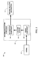
- FIG. 1 a block diagram of an information system 100 in accordance with an aspect of the present invention is shown.
- the information system 100 is comprised of an information system component 102 having an information component 104, a locating system 106, and a signal component 108.
- a signal 110 is received by the signal component 108 and processed into a signal strength indicator. This processing generally requires an analog to digital process.
- the signal component 108 can be capable of processing various signals, such as ambient radio waves and the like, including but not limited to, frequency modulated (FM) signals.
- FM frequency modulated
- the information component 104 utilizes the location to derive a set of relevant data.
- the relevancy of the data can be strictly based on location and / or a combination of location and user preferences (via a user input, not shown).
- the data can also be related to information from downloadable lookup tables that facilitate the process.
- GUI graphical user interface
- the locating system 106 stores the location. This allows location data to be utilized at a later point in time such as, for example, for desensitizing location due to device orientation (e.g ., averaging the last "X" number of location inferences). Tracking systems (e.g. , vehicle, package, personnel, equipment tracking and the like) can also employ this type of historical location data.
- the present invention can be utilized, for example, to facilitate police such as in determining where a stolen object such as a car has been, or to help a package delivery service determine how a particular package was transported after a delay in delivery was found. Parents could also employ an instance of the present invention to learn where their children have been for a previous period of time.
- employers can track employees and equipment to enhance performance.
- the present invention can also be utilized to track animals such as pets and the like.
- Computers can also report their locations automatically utilizing the present invention. This allows a computer to configure itself automatically based upon its location for such things as time zones, countries, and languages and the like.
- a means is provided to manage limited resources based upon location.
- the limited resources can include, but are not limited to, memory, power, and processing capability and the like.
- location can be used to discard stored data such as a map of an area that is not in the proximity of the current location of the device. This allows storage space for additional information about the present location that could not otherwise be stored.
- the location information can be utilized to facilitate other entities such as hardware devices and software programs and the like. These can include, but are not limited to, navigation systems, mapping software, tracking software, and locating software and the like.
- an instance of the present invention can be utilized in emergency-based devices for providing assistance in crisis situations such as medical emergencies, fires, floods, and infrastructure repair.
- Information such as water sources for fire control, building construction layouts, medical service locations, underground utilities, and weather reports and the like can be provided.
- the present invention can also be utilized to disseminate, based on location, time-sensitive information, advertising, weather reports, proximity information of an entity and the like.
- Proximity information of an entity can include, but is not limited to, buddy list type services for being notified when a friend or buddy is close to a device's location.
- a device could also be notified when other vehicles are in the area. This information can be utilized both as a positive effect to cluster objects and / or as a negative effect to warn of objects to allow distancing or disassociation to occur.
- a means is provided to group items based on an event location rather than timing of an event. For example, if a person took photographs while on a vacation that took them to the Grand Canyon then to Las Vegas and then back to the Grand Canyon, they could have their photographs automatically sorted via location ( e.g ., all Grand Canyon shots together) rather than via the actual sequence in which they were taken. Since the present invention can also be utilized indoors, it can group items from indoor events as well as outdoor events. For such applications, it is often unnecessary to have detailed latitude and longitudinal coordinates, but to simply know which city or portion of a city that pictures were taken in. Such applications may even keep the coarse location implicit, and use these properties for clustering and / or grouping items into distinct sets for viewing and / or sorting.
- the location system 200 is comprised of a locating component 202.
- the locating component 202 receives training data 204 utilized to train the locating component 202.
- the training data 204 can be comprised of hash code permutations and the like for various locality specific signals and the like. This data 204 can be calculated from information obtained via physically traveling to a location to obtain signal characteristics and / or via simulation software that provides the desired signal characteristics. In other instances of the present invention, training data is not utilized.
- a signal strength indicator input 206 allows the locating component 202 to determine its location based on signal strength indicators. The indicators are not required to be absolute in terms of actual signal strength.
- the locating component 202 processes the signal strength input 206 in a desensitized means with regard to absolute value to provide a location 208.
- the locating component 202 is generally comprised of an analysis component (not shown) that computes a rank vector which provides a means to rank signal strength indicators without regard to absolute values.
- the SPOT device 300 includes a wearable device 302, a weather forecast display 304, a traffic display 306, a restaurant display 308, and an entertainment display 310.
- One of the promises of ubiquitous computing is to connect users to important information as they move around in the world.
- One instance of the present invention leverages the small, low-power device platform of SPOT devices.
- SPOT provides users a means to receive critical notifications on a wristwatch-sized device as depicted in FIG. 3.
- the SPOT device is designed to listen for digitally encoded data such as news stories, weather forecasts, personal messages, traffic updates, and retail directories and the like transmitted on standard FM radio carrier frequencies, on bandwidth that is specially leased from the host radio stations.
- the device has the potential for connecting millions of people to valuable notifications and alerts.
- the SPOT device is constructed to minimize size and power consumption.
- the present invention is utilized, in one instance, to provide an extremely low-power method for identifying the location of devices such as, for example, SPOT devices. Since a SPOT device, utilizing the present invention, can determine location information, it supports new kinds of experiences, such as allowing the device to listen only for alerts that are relevant to particular locations. Previous basic methods for localizing data for transmission to particular devices relied on the limited range of FM radio signals. Thus, only devices within range of a particular radio tower received data relevant to that tower's coverage area. However, for certain messages, this location resolution is too coarse.
- GPS is a candidate for providing more precise location information, a GPS receiver would consume precious battery power and add volume and expense to an already densely packed device. Additionally, GPS is limited to outside usage where a direct link to satellites can be established.
- a means for localizing a device based on an analysis of ambient signal strengths from existing signal frequency emitters such as, for example, FM radio stations.
- existing signal frequency emitters such as, for example, FM radio stations.
- Systems and methods of the present invention which employ algorithms such as "RightSPOT,” can build on the SPOT technology that has already been developed for receiving notifications, including hardware and software for measuring signal strength on arbitrary frequencies in the FM band.
- the present invention utilizes a vector of radio signal strengths taken from different frequencies to identify location. Each time a location is to be inferred, the device scans through a set of FM frequencies and records the signal strength of each one. A standard SPOT device scans through multiple FM radio stations and measures signal strength in order to find a sufficiently powerful one transmitting SPOT data.
- a Received Signal Strength Indicator (RSSI) of SPOT is provided by an analogue-to-digital converter (ADC) in the device to the present invention.
- ADC analogue-to-digital converter
- the ADC and associated circuitry are generally not calibrated to measure RSSI in any certain units or to be consistent from device to device.
- SPOT technology such as RSSI
- other means for obtaining a signal strength indicator are compatible with the present invention.
- the present invention can utilize any signal strength indicator, whether with units or without units, that provides relative signal strengths.
- FIG. 4 a graph 400 illustrating signal strengths in accordance with an aspect of the present invention is shown.
- the vertical axis represents an input signal strength
- the horizontal axis is the measured signal strength (RSSI) from a device such as, for example, a SPOT device that provides RSSI.
- the curve 402 represents a fitted mathematical function to the measured data points represented by small triangles 404.
- the expected inconsistency among devices for measures of RSSI provides an obstacle as such variations make difficult attempts to generalize for reuse a single mapping between signal strengths and locations.
- One possible solution to this problem is to specially calibrate each device a priori using a source of known FM transmission strengths. The result of one of these tests is shown in FIG.
- signal strengths are also affected by the device's orientation, its surroundings, and the adjustment of an attaching means, such as a wrist band and the like, which can also serve as a signal receiving antenna. It would be nearly impossible to anticipate all these variable factors affecting absolute signal strength. If absolute signal strengths can be anticipated, a probabilistic framework like that of Roos, T., P. Myllymaki, and H. Tirri, in A Statistical Modeling Approach to Location Estimation; IEEE Transactions on Mobile Computing, 2002; 1(1): p. 59-69 would be appropriate. However, given the impracticality of discovering each device's response characteristics, an alternative method of comparing signal strengths is needed.
- the present invention employs transformations of signal strengths that provide more robust inferences.
- devices employing the present invention such as, for example, the RightSPOT algorithm, gave results of a ranking of a set of radio stations by their measured RSSI as described infra.
- the devices could not be depended upon to give consistent absolute signal strengths. Due to this fact, an alternate assumption is utilized based on the fact that relative signal strengths are relatively consistent (i.e., an ordered list of radio stations sorted by signal strength does not vary greatly for a given location). More precisely, it is assumed that a relationship between input signal strength and measured RSSI is monotonically increasing. In FIG.
- a graph 500 illustrating monotonicity of signal strengths in accordance with an aspect of the present invention is shown.
- the graph 500 shows that if a mobile device's measured RSSI is a monotonically increasing function of input signal strength, a signal strength order of inputs is also preserved. For instance, if A ⁇ B ⁇ C, these values transformed through differing RSSI-measuring functions are maintained in a substantially similar signal strength order. This allows the present invention to operate with a wide variety of devices in spite of device-to-device variations in how they measure signal strengths.
- the radio frequencies can represent different radio stations which can be identified by an index [1... n ]. Measuring RSSI of each station results in a set of ordered pairs giving a station index and signal strength of each radio station: ⁇ (1, s 1 ⁇ ,(2, s 2 ⁇ , ⁇ n , s n ) ⁇ .
- Equal signal strengths can be resolved, for example, by arbitrarily sorting, first detected sorting, most frequently detected sorting, and the like.
- rank vectors which are permutations of integers 1,2,..., n .
- Each rank vector can be mapped to an integer r ⁇ ⁇ 0,1,..., n !-1 ⁇ using a mixed-radix representation of the integers as described by Knuth, D.; Seminumerical Algorithms; in The Art of Computer Programming; 1981; Addisan-Wesley: Reading, Massachusetts; p. 64 (Algorithm P).
- a unique hash code is generated for each permutation of signal strengths.
- the present invention's classification scheme is motivated by an assumption that different locations will show different relative signal strengths. Ideally, each location would map to a single, unique value of r . In reality, due to noise, derived from such factors as a local tilt and position of a receiving unit, such as, for example, a SPOT antenna, changes in relative paths to ambient signal emitters based on different configurations and geometries associated with buildings and geographical terrain, each location produces a distribution of different r' s.
- classification in accordance with various aspects of the present invention can employ a probabilistic and / or statistical-based analysis (e.g ., factoring into the analysis utilities and costs) to prognose or infer an action that a user desires to be automatically performed.
- a support vector machine (SVM) classifier can be employed - an SVM generally operates by finding a dynamically changing hypersurface in the space of possible inputs.
- SVM support vector machine
- Other directed and undirected models classification approaches include, e.g. , na ⁇ ve Bayes, Bayesian networks, decision trees, and probabilistic classification models providing different patterns of independence can be employed. Classification as used herein also is inclusive of statistical regression that is utilized to develop models of priority.
- FIG. 6 a three-dimensional graph 600 illustrating hash code permutations in accordance with an aspect of the present invention is depicted.
- the graph 600 is comprised of a normalized histogram axis 602, a location axis 604, and a derived permutation hash code axis 606.
- a receiving device such as, for example, a SPOT device
- I 1,2,..., L indexes over the locations
- i 1,2,..., N l indexes over the hash codes observed at location l .
- a normalized histogram of the hash codes is constructed to approximate a discrete probability distribution of hash codes seen at that point, An example of these normalized histograms for six locations and three frequencies is shown in FIG. 6.
- a probability of being in any of the L locations is computed using Bayes rule:
- a classifier such as, for example, a Bayes classifier, identifies a class with a maximum a posteriori probability, i.e.: Algorithmically, this means that for an observations*, a normalized histogram is consulted ( e.g. , FIG. 6), looking up values of over a full range of locations l ⁇ ⁇ 1,2,..., L ⁇ , and taking a location l with a largest value of
- the map 700 is comprised of six locations 702-712 representing suburbs of Seattle. Each device was programmed to measure signal strengths of 32 different local FM radio stations. The devices were then transported to six different suburbs in the Seattle area, logging all 32 signal strengths, taking one measure of each station per second. In each suburb, an average of about 720 readings were taken ( ⁇ 10 minutes) while moving around the suburb's retail core.
- the retail core was selected as compelling applications for one instance of the present invention involve, for example, retail businesses sending out time-sensitive offers and listing of local attractions.
- FIG. 8 a graph 800 illustrating radio signal strength indicator values in accordance with an aspect of the present invention is depicted.
- the graph 800 is comprised of raw RSSI data 802 and median filtered data 804.
- Raw RSSI data from the devices was found to be noisy, as shown in FIG. 8, so a windowed median filter was applied to the data, replacing each RSSI with a median of itself and a preceding 29 unfiltered values.
- a windowed median filter was applied to the data, replacing each RSSI with a median of itself and a preceding 29 unfiltered values.
- filtering means can be implemented in place of the windowed median filter.
- Testing was done by alternately picking data from one of the three devices as the basis for normalized histograms and testing with data from the other two. This was a more realistic test than merely testing each device against itself, because ultimately the devices, in one instance of the present invention, depend on one pre-programmed set of histograms for determining their location.
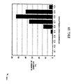
- the example 900 is comprised of an ambient signal emitter quantity 902, a subset of ambient signal emitters 904, and a classification accuracy result 906. This shows how often the device was correctly classified into one of the six suburbs used for testing.
- experimentation was accomplished, such as, for example, using a much reduced subset of the 32 recorded radio stations.
- n radio stations For each test of n radio stations, a set of different combinations of stations to use for classifying location were examined. The results, in terms of classification accuracy, are shown in FIG. 9.
- the present invention can be utilized with fewer ambient signal emitters and still be utilized to locate a device.
- ambient signal emitters e.g ., radio transmitters and the like
- This example demonstrates the feasibility of using existing ambient signal emitters, such as, for example, FM radio signals, to localize a device down to a suburb utilizing one instance of the present invention.
- existing technology such as, for example, SPOT devices
- existing hardware can be leveraged to measure signal strengths, such as, for example, FM radio signal strengths, so that the capability for localization, in one instance of the present invention, only requires the addition of a small amount of software to an existing configuration.
- Different devices measure signal strengths differently, and signal strengths are also affected by many other variables.
- the present invention employing, for example, a Bayesian classification algorithm, does not utilize absolute signal strengths, but instead utilizes a ranking of signal strengths to facilitate in ensuring robustness across devices and other variables.
- the present invention can also be employed to anticipate signal strength characteristics of different locations without actually visiting them to obtain signal characteristics or "training data.”
- RadioSoft's ComStudy software (see generally, Internet website http:/www.radiosoft.com) and the like is utilized to generate simulated FM radio signal strength maps, Such a simulation can also facilitate in determining a good subset of radio stations to listen to for best localization.
- Methodologies for optimal usage of radio strength maps includes the harnessing of probabilistic methods to learn how the reliability and potential biases of simulations varies from actual received data based on such features as topology, geometric relationships between topology and / or transmitters, and the presence of buildings and other man-made structures.
- notions of persistence of location can be utilized to fill in gaps in confidence that may show up. For example, if a device is not confident in a particular location, assume that device is closest to a location last sensed with confidence if the time is not great enough to allow for distant travel.
- the ComStudy software supports many radio propagation models that can be utilized to predict FM radio maps.
- the Longley-Rice model (see, P.L. Rice, A.G. Longley, K.A. Norton, and Barsis, A.P.; Transmission Loss Predictions for Tropospheric Communication Circuits; National Bureau of Standards Technical Note 101, January, 1967) was chosen in this example of an instance of the present invention, for its known accuracy. It is generally the most accurate of the choices since it incorporates reflection, refraction (bending of the rays as they rise through the atmosphere), and several types of diffraction (spilling of signal over hills).
- the model utilizes a terrain map to simulate the effect of hills and valleys.
- ComStudy parameterizes each radio station transmitter by its frequency, transmitting power, and location (latitude, longitude). For each transmitter, a field strength matrix is generated. The matrix is a grid of rectangular cells spread over a chosen area on the ground, with each cell containing signal level information from a transmitter in question. The width of the cells was chosen to be 6 arc seconds (about 185 meters north-south and 124 meters east-west). This is equivalent to having 40 points (cells) per square kilometer. ComStudy then applies a chosen propagation model to calculate field strength in the center of each cell. In this example, maps were generated for 28 local FM radio stations in the Seattle, Washington area.
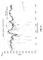
- FIG. 10 a histogram 1000 of Spearman's correlations between measured signal strength and simulated signal strength in accordance with an aspect of the present invention is depicted.
- the histogram 1000 shows that more than 95% of the measured rankings were correlated with the simulated rankings with a factor of at least 0.6 on a scale of [-1 ... 1]. This indicates that the simulated results are sufficiently accurate for determining a location of a SPOT watch. Even better correlation is obtainable if the number of stations is reduced as discussed in more detail infra.
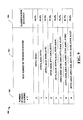
- FIG. 11 a table 1100 of simulated signal strengths for radio stations in the Seattle area in accordance with an aspect of the present invention is depicted.
- the table 1100 shows seven groups of stations along with frequencies, means, and variances of correlated stations inside each group. Selected stations from each group are shown with bold-faced type.
- FIG. 12 a histogram 1200 of Spearman's correlations between measured signal strength and simulated signal strength of seven chosen stations in accordance with an aspect of the present invention is illustrated.
- the histogram 1200 shows a significant improvement over the similar histogram 1000 with 28 stations (FIG. 10), with an even higher correlation between measured and simulated signal strengths. More than 95% of the measured signal strength rank vectors are correlated with the simulated signal strength with a factor of 0.8 or above. This further emphasizes that the simulated results are valid to employ for determining a location of a SPOT watch and similar devices and the like.
- Each cell of the simulated signal strength maps is converted to a rank hash code, which is ultimately utilized for inferring location from measured rank hash codes.
- the simulated signal strength maps are generated on a grid with cells about 124 meters wide (east-west) and 185 meters high (north-south). This is near the limit of the ComStudy's maximum simulation resolution, and it is much finer than required for this example of the present invention. Furthermore, this fine resolution provides 442,806 cells (811 east-west by 546 north-south) to represent a test area around Seattle.
- the rank hash code ranges over [0 ... 7!-1], meaning that each fine cell needs a 13-bit integer to represent its hash code.
- the radio map would then need 811 x 546 x 13/8 ⁇ 0.7 MB to represent the fine grid of hash codes for the test area. Generally speaking, this is too large for small, resource-limited devices.
- each coarse cell is represented as a histogram of rank hash codes from its underlying fine cells.
- Each coarse cell's histogram is normalized to give an estimate of a probability distribution of rank hash codes for a cell.
- this likelihood estimate is P' ( r
- the histograms are sparsely populated because of a large number of possible rank hash codes. Due to noise, orientation of a device, and unsimulated radio propagation effects, rank hash codes in a cell is often measured for which a simulated likelihood P' ( r
- the (unnormalized) smoothed likelihood is computed as:
- S(r,r') is a Spearman correlation coefficient between rank vectors represented by hash codes r and r '. is then normalized over r into to give a smoothed likelihood function of a rank hash code given a coarse cell.
- ⁇ s serves as a smoothing parameter, with higher values giving more smoothing.
- the supra example was performed in the greater Seattle area with a SPOT watch programmed to measure signal strengths of a reduced set of 7 local FM radio stations.
- the SPOT watch was transported around the area, logging signal strengths of all 7 stations, taking one 7-station scan per second, resulting in about 3920 readings for each station along with GPS location readings. Meanwhile, a simulated radio map for the 7 stations was generated.
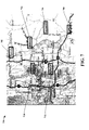
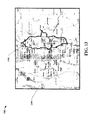
- FIG. 13 a map 1300 illustrating a test area in accordance with an aspect of the present invention is depicted.
- the map 1300 shows a drive path 1302 along with a coarse grid 1304 with cell width 7 km that was used for inferring a location.
- the drive path 1302 included both highways and local roads.
- the example illustrates that a device's location can be determined with the present invention down to an accuracy of less than 10 miles ( ⁇ 16 kilometers), utilizing simple histograms built on top of a simulated radio map.
- correlation threshold ⁇ s temporal window size K
- grid cell width w grid cell width
- a coarse grid cell width w is an important parameter in terms of affecting accuracy of a location inference.
- Increasing the coarse cell width has an advantage of having more fine grid cells in a histogram estimate of P '( r
- increasing a cell width decreases an overall number of cells in the grid and thus reduces computational overhead.
- location resolution naturally decreases.
- graphs 1500, 1502 illustrate probability density function and cumulative density function errors for a given cell width in accordance with an aspect of the present invention.
- PDF error probability density function
- CDF cumulative density function
- the second factor that affects accuracy of an inference algorithm is a correlation smoothing threshold ⁇ s
- the correlation threshold was introduced to smooth a likelihood estimate. Therefore, increasing ⁇ k will result in filling more gaps in a histogram-based estimate of P' ( r
- a graph 1600 illustrating a relation between correlating threshold and median error in accordance with an aspect of the present invention is depicted.
- K the temporal window size
- K the number of seconds of data utilized to infer position.
- increasing K enhances accuracy; however, it also increases memory storage and computational power requirements.
- the present invention provides a means for inferring a location of a device based on ambient signal strengths such as FM radio signal strengths and the like. Its advantages include a wide coverage of FM radio, spanning indoor and outdoor locations, and the readiness of a target device such as a SPOT device and the like for measuring radio signal strengths, providing an accuracy of several miles.
- the present invention is robust to measurement differences between devices, relying on inferences based on rankings of ambient signals rather than on their absolute signal strengths. No manual survey of signal strength as a function of location is necessary when employing simulated signal strengths. By utilizing smoothed histograms of rank hash codes, a device's location can be inferred down to an accuracy of less than 10 miles ( ⁇ 16 kilometers).
- the extremely low resource utilizing employed by the present invention allows it to provide functionality to resource limited devices such as small, wearable devices.
- a method is employed to identify which radio station histograms to transmit to a device, given a limited storage capacity of certain devices.
- classification accuracy can be boosted by smoothing position inferences over time, exploiting knowledge about location adjacencies, and adhering to constraints about how fast devices are expected to move between locations.
- decision-theoretic approaches to minimizing misdiagnosis given probability distributions over locations.
- still yet another instance of the present invention employs other fundamental representations that capture properties of relative signal strength beyond rank orderings, including methods that capture strength ratios and relationships among groups of signal emitters clustered by strengths.
- program modules include routines, programs, objects, data structures, etc., that perform particular tasks or implement particular abstract data types.
- functionality of the program modules may be combined or distributed as desired in various instances of the present invention.
- the method 1800 starts 1802 by providing signal strength indicators 1804.
- the indicators are generally representations of signals such as ambient signals and the like from signal sources such as towers, building antennae, and mobile units (including terrain and aeronautical units and the like) and the like.
- the signals can include, but are not limited to, frequency modulated signals, amplitude modulated signals, ultra high-frequency signals, very high-frequency signals, and the like and even more directional signals such as upper microwave signals and the like.
- the present invention can also be adapted to operate with higher frequency-receiving devices capable of indicating signal strengths of infrared, x-ray, and cosmic ray and the like.
- lower frequency receiving devices which provide reception for ultra-sonics, sonics, and infra-sonics and the like are operable with the present invention as well.
- the present invention can also account for time-varying signals and signals emitted from mobile platforms.
- Terrain-sensitive propagation models can also be utilized to account for variations in signals due to terrain obstructions.
- other propagation models can be utilized to account for such things as reflections from large structures such as buildings, monuments, and man-made objects and the like.
- velocity prediction models the present invention can also be utilized to determine the velocity of a device as well as its location.
- the signal strength indicators are not limited to only those indicators that provide accurate strengths in an absolute in scale.
- the present invention can accept signal strength indicators without any units associated with the indicators. Once the signal strength indicators are provided, a location is determined based upon the provided signal strength indicators 1806, ending the flow 1808. The determination is generally based upon an algorithm that allows a distribution to be leveraged to provide a location through inferencing. In one aspect of the present invention, a Bayesian classification algorithm is utilized that does not rely upon absolute signal strengths. Instead, a ranking of signal strengths is employed to facilitate in ensuring that variations such as signal detection errors, calibration errors, and unknown signal strength indicator sources and the like do not impact the location determination.
- FIG. 19 another flow diagram of a method 1900 of locating a device in accordance with an aspect of the present invention is shown.
- the method 1900 starts 1902 by obtaining ambient signals such as, for example, radio frequency signals from such sources, for example, as commercial FM radio towers and / or stations 1904.
- a list of the radio frequencies is then scanned 1906 and measured signal strength vectors are determined 1908.
- the relative strengths are then sorted and a rank vector is computed for the frequencies 1910.
- Hash codes are then generated based on permutations of the signal strengths 1912.
- Hash codes are then obtained from each desired location to train a location system 1914. Normalized histograms are then constructed from the hash codes 1916.
- a probability is then computed via, for example, Bayes rule 1918.
- a classifier such as, for example, a Bayesian classifier, is then utilized to identify a maximum a posteriori probability, indicating that a device is most likely in that particular location 1920, ending the flow 1922.
- a flow diagram of a method 2000 of training a locating device in accordance with an aspect of the present invention is illustrated.
- the method 2000 starts 2002 by positioning a device that receives ambient signals in a particular location 2004.
- Ambient signals such as radio frequency signals and the like, are each scanned multiple times to obtain their signal strengths 2006.
- Rank information such as rank hash codes and the like, is then computed for each scan 2008.
- a normalized histogram of rank information, such as the rank hash codes, is generated for the particular location and stored 2010.
- a determination is then made as to whether another location is desired to obtain data from 2012. If yes, the device is transported to another location 2004 and the method 2000 starts again. If no more locations are desired, the flow ends 2014.
- FIG. 21 a flow diagram of a method 2100 of smoothing histograms utilized for locating a device in accordance with an aspect of the present invention is shown.
- the method 2100 starts 2102 by computing coarse grid cell histograms based on underlying fine grid cells 2104.
- the coarse grid cell histograms are then normalized 2106. This provides an estimate of a probability distribution of rank hash codes for a cell.
- a correlation threshold value is then selected 2108. This permits control of smoothing of sparsely populated histograms, with higher values giving more smoothing.
- Histogram bins with Spearman correlation coefficients above the correlation threshold value are then determined 2110. A maximum value over all histogram bins that are above the correlation threshold value is calculated 2112. Each histogram bin above the correlation threshold value has its value replaced by the maximum value 2114, ending the flow 2116.
- the smoothed likelihood is computed as: where S(r, r') is a Spearman correlation coefficient between rank vectors represented by hash codes r and r' . is then normalized over r into to give a smoothed likelihood function of a rank hash code given a coarse cell.
- a flow diagram of a method 2200 of smoothing location inferences in accordance with an aspect of the present invention is depicted.
- the method 2200 starts 2202 by obtaining a history of signal strength scans 2204.
- a location inference smoothing value " K " temporary window size
- a most frequently inferred location over the last " K " signal strength scans is then determined 2208, ending the flow 2210.
- the most frequently inferred location becomes the location utilized for an underlying device. This is frequently done to prevent the device from "jumping" from location to location due to orientation movement of the device and other environmental influences.
- smoothing the inferenced location a substantially steady value is shown by the device.
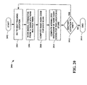
- FIG. 23 a flow diagram of a method 2300 of optimizing ambient signal sets for utilization in locating a device in accordance with an aspect of the present invention is shown.
- the method 2300 starts 2302 by obtaining a set of ambient signals and their respective signal strengths 2304.
- a Pearson's correlation coefficient is then calculated between all pairs of signal sources in the set 2306.
- pairing of signal sources is based upon spatially corresponding points on a simulated signal strength map and the like. Pearson's correlation coefficient represents a standard linear correlation coefficient and not a rank correlation.
- a correlation threshold value is then selected 2308.
- a typical value for this correlation threshold in one instance of the present invention is approximately 0.95. Signal sources that correlate greater than the selected correlation threshold value are grouped together 2310.
- a signal with the highest average signal strength of each group is then selected to represent that group 2312, ending the flow 2314.
- This method 2300 reduces the number of rank vectors to be utilized in locating a device by several orders of magnitude. It 2300 is also particularly useful when ambient signals originate from a single source, eliminating source redundancy.
- Instances of the present invention can include inclusion of a means for accepting input and / or feedback from users either on a programming device and / or an endpoint device itself.
- Such input can include regions that a user wishes to exclude from inference, e.g. , "only consider this particular subset of areas within this greater city region; I will not be traveling in other areas.”
- Such constraints can enhance the accuracy of the inferences of a system by narrowing the scope of locations.
- users can input feedback about the accuracy of a system, e.g. , "this is incorrect; this is correct," e.g ., via simple button pushes. Such feedback can be used to enhance the accuracy of future inferences.
- FIG. 24 and the following discussion is intended to provide a brief, general description of a suitable computing environment 2400 in which the various aspects of the present invention may be implemented. While the invention has been described above in the general context of computer-executable instructions of a computer program that runs on a local computer and / or remote computer, those skilled in the art will recognize that the invention also may be implemented in combination with other program modules. Generally, program modules include routines, programs, components, data structures, etc. , that perform particular tasks and / or implement particular abstract data types.
- inventive methods may be practiced with other computer system configurations, including single-processor or multi-processor computer systems, minicomputers, mainframe computers, as well as personal computers, hand-held computing devices, microprocessor-based and / or programmable consumer electronics, and the like, each of which may operatively communicate with one or more associated devices.
- the illustrated aspects of the invention may also be practiced in distributed computing environments where certain tasks are performed by remote processing devices that are linked through a communications network. However, some, if not all, aspects of the invention may be practiced on stand-alone computers.
- program modules may be located in local and / or remote memory storage devices.
- a component is intended to refer to a computer-related entity, either hardware, a combination of hardware and software, software, or software in execution.
- a component may be, but is not limited to, a process running on a processor, a processor, an object, an executable, a thread of execution, a program, and a computer.
- an application running on a server and / or the server can be a component.
- a component may include one or more subcomponents.
- an exemplary system environment 2400 for implementing the various aspects of the invention includes a conventional computer 2402, including a processing unit 2404, a system memory 2406, and a system bus 2408 that couples various system components, including the system memory, to the processing unit 2404.
- the processing unit 2404 may be any commercially available or proprietary processor.
- the processing unit may be implemented as multi-processor formed of more than one processor, such as may be connected in parallel.
- the system bus 2408 may be any of several types of bus structure including a memory bus or memory controller, a peripheral bus, and a local bus using any of a variety of conventional bus architectures such as PCI, VESA, Microchannel, ISA, and EISA, to name a few.
- the system memory 2406 includes read only memory (ROM) 2410 and random access memory (RAM) 2412.
- ROM read only memory
- RAM random access memory
- BIOS basic input/output system
- BIOS basic routines that help to transfer information between elements within the computer 2402, such as during start-up, is stored in ROM 2410.
- the computer 2402 also may include, for example, a hard disk drive 2416, a magnetic disk drive 2418, e.g ., to read from or write to a removable disk 2420, and an optical disk drive 2422, e.g. , for reading from or writing to a CD-ROM disk 2424 or other optical media.
- the hard disk drive 2416, magnetic disk drive 2418, and optical disk drive 2422 are connected to the system bus 2408 by a hard disk drive interface 2426, a magnetic disk drive interface 2428, and an optical drive interface 2430, respectively.
- the drives 2416-2422 and their associated computer-readable media provide nonvolatile storage of data, data structures, computer-executable instructions, etc. for the computer 2402.
- computer-readable media refers to a hard disk, a removable magnetic disk and a CD
- other types of media which are readable by a computer such as magnetic cassettes, flash memory cards, digital video disks, Bernoulli cartridges, and the like, can also be used in the exemplary operating environment 2400, and further that any such media may contain computer-executable instructions for performing the methods of the present invention.
- a number of program modules may be stored in the drives 2416-2422 and RAM 2412, including an operating system 2432, one or more application programs 2434, other program modules 2436, and program data 2438.
- the operating system 2432 may be any suitable operating system or combination of operating systems.
- the application programs 2434 and program modules 2436 can include inferring a location of a device in accordance with an aspect of the present invention.
- a user can enter commands and information into the computer 2402 through one or more user input devices, such as a keyboard 2440 and a pointing device ( e.g. , a mouse 2442).
- Other input devices may include a microphone, a joystick, a game pad, a satellite dish, wireless remote, a scanner, or the like.
- These and other input devices are often connected to the processing unit 2404 through a serial port interface 2444 that is coupled to the system bus 2408, but may be connected by other interfaces, such as a parallel port, a game port or a universal serial bus (USB).
- a monitor 2446 or other type of display device is also connected to the system bus 2408 via an interface, such as a video adapter 2448.
- the computer 2402 may include other peripheral output devices (not shown), such as speakers, printers, etc.
- the computer 2402 can operate in a networked environment using logical connections to one or more remote computers 2460.
- the remote computer 2460 may be a workstation, a server computer, a router, a peer device or other common network node, and typically includes many or all of the elements described relative to the computer 2402, although, for purposes of brevity, only a memory storage device 2462 is illustrated in FIG. 24.
- the logical connections depicted in FIG. 24 can include a local area network (LAN) 2464 and a wide area network (WAN) 2466.
- LAN local area network
- WAN wide area network
- the computer 2402 When used in a LAN networking environment, for example, the computer 2402 is connected to the local network 2464 through a network interface or adapter 2468.
- the computer 2402 When used in a WAN networking environment, the computer 2402 typically includes a modem (e.g ., telephone, DSL, cable, etc.) 2470, or is connected to a communications server on the LAN, or has other means for establishing communications over the WAN 2466, such as the Internet.
- the modem 2470 which can be internal or external relative to the computer 2402, is connected to the system bus 2408 via the serial port interface 2444.
- program modules including application programs 2434) and / or program data 2438 can be stored in the remote memory storage device 2462. It will be appreciated that the network connections shown are exemplary, and other means (e.g., wired or wireless) of establishing a communications link between the computers 2402 and 2460 can be used when carrying out an aspect of the present invention.
- the present invention has been described with reference to acts and symbolic representations of operations that are performed by a computer, such as the computer 2402 or remote computer 2460, unless otherwise indicated. Such acts and operations are sometimes referred to as being computer-executed. It will be appreciated that the acts and symbolically represented operations include the manipulation by the processing unit 2404 of electrical signals representing data bits which causes a resulting transformation or reduction of the electrical signal representation, and the maintenance of data bits at memory locations in the memory system (including the system memory 2406, hard drive 2416, floppy disks 2420, CD-ROM 2424, and remote memory 2462) to thereby reconfigure or otherwise alter the computer system's operation, as well as other processing of signals.
- the memory locations where such data bits are maintained are physical locations that have particular electrical, magnetic, or optical properties corresponding to the data bits.
- FIG. 25 is another block diagram of a sample computing environment 2500 with which the present invention can interact.
- the system 2500 further illustrates a system that includes one or more client(s) 2502.
- the client(s) 2502 can be hardware and / or software (e.g., threads, processes, computing devices).
- the system 2500 also includes one or more server(s) 2504.
- the server(s) 2504 can also be hardware and / or software (e.g., threads, processes, computing devices).
- the server(s) 2504 can house threads to perform transformations by employing the present invention, for example.
- One possible communication between a client 2502 and a server 2504 may be in the form of a data packet adapted to be transmitted between two or more computer processes.
- the system 2500 includes a communication framework 2508 that can be employed to facilitate communications between the client(s) 2502 and the server(s) 2504.
- the client(s) 2502 are operably connected to one or more client data store(s) 2510 that can be employed to store information local to the client(s) 2502.
- the server(s) 2504 are operably connected to one or more server data store(s) 2506 that can be employed to store information local to the server(s) 2504.
- a data packet transmitted between two or more computer components that facilitate locating a device is comprised of, at least in part, information relating to a locating system that determines, based on at least one ambient frequency signal indicator, an approximation of a location of a device.
- a computer readable medium storing computer executable components of a system for facilitating locating a device is comprised of, at least in part, a locating system that determines, based on at least one ambient frequency signal indicator, an approximation of a location of a device.
- a location is determined based upon signal strength indicators based upon mobile and / or stationary signal emitters. Data transmitted from mobile units is utilized to provide stabilization for determining a location.
- radiation patterns of signal emitters are utilized in the determination of a location.
- systems and / or methods of the present invention can be utilized in locating systems facilitating computer components and non-computer related components alike. Further, those skilled in the art will recognize that the systems and / or methods of the present invention are employable in a vast array of electronic related technologies, including, but not limited to, computers, servers and / or handheld electronic devices, affixable electronic devices (e.g., magnetic attachment, hook and loop attachment, hook attachment, adhesive attachment, etc.), wearable electronic devices (e.g ., watches, eye glasses, clothing items, hearing aids, necklaces, bracelets, belts, ankle bracelets, tie tacks, rings, etc.), and the like.
- affixable electronic devices e.g., magnetic attachment, hook and loop attachment, hook attachment, adhesive attachment, etc.
- wearable electronic devices e.g ., watches, eye glasses, clothing items, hearing aids, necklaces, bracelets, belts, ankle bracelets, tie tacks, rings, etc.
Landscapes
- Physics & Mathematics (AREA)
- General Physics & Mathematics (AREA)
- Engineering & Computer Science (AREA)
- Radar, Positioning & Navigation (AREA)
- Remote Sensing (AREA)
- Life Sciences & Earth Sciences (AREA)
- Atmospheric Sciences (AREA)
- Probability & Statistics with Applications (AREA)
- Position Fixing By Use Of Radio Waves (AREA)
- Mobile Radio Communication Systems (AREA)
Applications Claiming Priority (4)
| Application Number | Priority Date | Filing Date | Title |
|---|---|---|---|
| US742208 | 1985-06-07 | ||
| US48927403P | 2003-07-22 | 2003-07-22 | |
| US489274P | 2003-07-22 | ||
| US10/742,208 US7319877B2 (en) | 2003-07-22 | 2003-12-19 | Methods for determining the approximate location of a device from ambient signals |
Publications (2)
| Publication Number | Publication Date |
|---|---|
| EP1500949A1 true EP1500949A1 (fr) | 2005-01-26 |
| EP1500949B1 EP1500949B1 (fr) | 2013-02-13 |
Family
ID=33493637
Family Applications (1)
| Application Number | Title | Priority Date | Filing Date |
|---|---|---|---|
| EP04103175A Expired - Lifetime EP1500949B1 (fr) | 2003-07-22 | 2004-07-05 | Procédés pour déterminer la position approximative d'un dispositif à partir des signaux ambiants |
Country Status (10)
| Country | Link |
|---|---|
| US (1) | US7319877B2 (fr) |
| EP (1) | EP1500949B1 (fr) |
| JP (1) | JP4936647B2 (fr) |
| KR (1) | KR101120728B1 (fr) |
| CN (1) | CN100593123C (fr) |
| AU (1) | AU2004203017B2 (fr) |
| BR (1) | BRPI0402751A (fr) |
| CA (1) | CA2472995C (fr) |
| MX (1) | MXPA04006633A (fr) |
| RU (1) | RU2391701C2 (fr) |
Cited By (3)
| Publication number | Priority date | Publication date | Assignee | Title |
|---|---|---|---|---|
| GB2424139A (en) * | 2005-03-10 | 2006-09-13 | Avaya Tech Llc | System and method for estimating the location of terminals in a wireless network environment |
| CN105974420A (zh) * | 2016-07-13 | 2016-09-28 | 南京邮电大学 | 一种基于反射锥的超声波定位系统 |
| US9781697B2 (en) | 2014-06-20 | 2017-10-03 | Samsung Electronics Co., Ltd. | Localization using converged platforms |
Families Citing this family (83)
| Publication number | Priority date | Publication date | Assignee | Title |
|---|---|---|---|---|
| US7899467B2 (en) * | 1998-09-22 | 2011-03-01 | Polaris Wireless, Inc. | Estimating the location of a wireless terminal based on the traits of the multipath components of a signal |
| US7738881B2 (en) * | 2003-07-22 | 2010-06-15 | Microsoft Corporation | Systems for determining the approximate location of a device from ambient signals |
| US20050071498A1 (en) * | 2003-09-30 | 2005-03-31 | Farchmin David W. | Wireless location based automated components |
| US20050113115A1 (en) * | 2003-10-31 | 2005-05-26 | Haberman William E. | Presenting broadcast received by mobile device based on proximity and content |
| US20050096039A1 (en) * | 2003-10-31 | 2005-05-05 | Haberman William E. | Storing new and updated broadcasts in mobile device |
| JP4755441B2 (ja) * | 2005-04-25 | 2011-08-24 | 株式会社日立製作所 | 設計支援方法及びシステム |
| US7653400B2 (en) * | 2005-06-28 | 2010-01-26 | Research In Motion Limited | Probabilistic location prediction for a mobile station |
| US8089407B2 (en) * | 2005-12-16 | 2012-01-03 | Alcatel Lucent | System and method for model-free position estimation and tracking |
| WO2007075553A2 (fr) * | 2005-12-16 | 2007-07-05 | Raytheon Utd Inc. | Systeme et procede de localisation |
| JP2007316068A (ja) * | 2006-05-22 | 2007-12-06 | Polaris Wireless Inc | 無線端末の居場所の予測方法 |
| JP2007316070A (ja) | 2006-05-22 | 2007-12-06 | Polaris Wireless Inc | 無線端末の居場所の予測方法 |
| US7783303B1 (en) * | 2006-07-14 | 2010-08-24 | Carrier Iq, Inc. | Systems and methods for locating device activity in a wireless network |
| US20080032628A1 (en) * | 2006-08-02 | 2008-02-07 | Nokia Corporation | Method and apparatus for detecting trends in received signal strength |
| US20080051989A1 (en) * | 2006-08-25 | 2008-02-28 | Microsoft Corporation | Filtering of data layered on mapping applications |
| US8886210B1 (en) * | 2007-01-16 | 2014-11-11 | Cisco Technology, Inc. | Resolving ambiguity with respect to locationing and classification of wireless transmitters |
| KR100875925B1 (ko) * | 2007-03-22 | 2008-12-26 | 한국전자통신연구원 | 고 전력효율 광-무선 송출기 |
| US7941159B2 (en) * | 2007-05-25 | 2011-05-10 | Broadcom Corporation | Position determination using received broadcast signals |
| US20080291086A1 (en) * | 2007-05-25 | 2008-11-27 | Broadcom Corporation | Position determination using available positioning techniques |
| US7990314B2 (en) | 2008-06-30 | 2011-08-02 | Liao Henry H | Method and system for locating a geographical position using broadcast frequency modulation signals |
| EP2163915A1 (fr) * | 2008-09-15 | 2010-03-17 | Géomatic Ingénierie S.A. | Procédé de détermination d'au moins un axe sur lequel se déplace un équipement mobile |
| JP5396798B2 (ja) * | 2008-09-30 | 2014-01-22 | Tdk株式会社 | 活物質材料、それを用いた正極及びリチウムイオン二次電池 |
| US8527956B2 (en) * | 2008-12-23 | 2013-09-03 | International Business Machines Corporation | Workload performance projection via surrogate program analysis for future information handling systems |
| US9135142B2 (en) * | 2008-12-24 | 2015-09-15 | International Business Machines Corporation | Workload performance projection for future information handling systems using microarchitecture dependent data |
| JP2010197050A (ja) * | 2009-02-20 | 2010-09-09 | Nippon Telegr & Teleph Corp <Ntt> | 位置推定システム |
| US8307184B1 (en) * | 2009-06-01 | 2012-11-06 | Nissani Nissensohn Daniel Nathan | Communication and memory capacity enhancement method and apparatus |
| US8433250B2 (en) * | 2010-01-29 | 2013-04-30 | Ntt Docomo, Inc. | Estimating whether a wireless terminal is indoors using pattern classification |
| US8493205B2 (en) | 2010-01-29 | 2013-07-23 | Ntt Docomo, Inc. | Search area reduction based on indoor detection for estimating the location of a wireless terminal |
| US8237612B2 (en) * | 2010-02-24 | 2012-08-07 | Microsoft Corporation | Inferring beacon positions based on spatial relationships |
| US8570993B2 (en) | 2010-05-20 | 2013-10-29 | At&T Mobility Ii Llc | Wi-Fi intelligent selection engine |
| RU2434299C1 (ru) * | 2010-07-19 | 2011-11-20 | Открытое акционерное общество "Авангард" | Sos-система для автомагистралей |
| CN101938694A (zh) * | 2010-08-26 | 2011-01-05 | 惠州Tcl移动通信有限公司 | 一种移动终端及其设置信息更新方法和装置 |
| CN102401890B (zh) * | 2010-09-17 | 2013-11-27 | 成都点阵科技有限公司 | 根据无线电信号强度使用多维图形定位信号发射源的方法 |
| WO2012046202A1 (fr) | 2010-10-08 | 2012-04-12 | Koninklijke Philips Electronics N.V. | Câble d'attache souple comportant des capteurs intégrés pour un suivi d'instrument dynamique |
| US9880604B2 (en) | 2011-04-20 | 2018-01-30 | Microsoft Technology Licensing, Llc | Energy efficient location detection |
| US8589012B2 (en) * | 2011-06-14 | 2013-11-19 | Crown Equipment Limited | Method and apparatus for facilitating map data processing for industrial vehicle navigation |
| US8805956B1 (en) * | 2011-09-27 | 2014-08-12 | Trend Micro, Inc. | Data leakage prevention in cloud-endpoint model |
| US9059802B2 (en) * | 2011-11-09 | 2015-06-16 | At&T Mobility Ii Llc | Received signal strength indicator snapshot analysis |
| US9270804B2 (en) * | 2011-12-01 | 2016-02-23 | Koninklijke Philips N.V. | Method, wireless device and wireless communications system to guide a user of a wireless device to establish an optimal wireless direct link to another wireless device |
| US9189252B2 (en) * | 2011-12-30 | 2015-11-17 | Microsoft Technology Licensing, Llc | Context-based device action prediction |
| US9084932B2 (en) | 2012-01-13 | 2015-07-21 | Gtech Canada Ulc | Automated discovery of gaming preferences |
| US9295908B2 (en) | 2012-01-13 | 2016-03-29 | Igt Canada Solutions Ulc | Systems and methods for remote gaming using game recommender |
| US9280867B2 (en) | 2012-01-13 | 2016-03-08 | Igt Canada Solutions Ulc | Systems and methods for adjusting 3D gaming images for mobile gaming |
| US9536378B2 (en) | 2012-01-13 | 2017-01-03 | Igt Canada Solutions Ulc | Systems and methods for recommending games to registered players using distributed storage |
| US9558625B2 (en) | 2012-01-13 | 2017-01-31 | Igt Canada Solutions Ulc | Systems and methods for recommending games to anonymous players using distributed storage |
| US8953478B2 (en) * | 2012-01-27 | 2015-02-10 | Intel Corporation | Evolved node B and method for coherent coordinated multipoint transmission with per CSI-RS feedback |
| US9125067B2 (en) * | 2012-02-03 | 2015-09-01 | Commscope Technologies Llc | System and method for mobile location using ranked parameter labels |
| US9279878B2 (en) | 2012-03-27 | 2016-03-08 | Microsoft Technology Licensing, Llc | Locating a mobile device |
| US8983490B2 (en) | 2012-03-27 | 2015-03-17 | Microsoft Technology Licensing, Llc | Locating a mobile device |
| US9191886B2 (en) * | 2012-06-01 | 2015-11-17 | Crestron Electronics Inc. | Commissioning of wireless devices in personal area networks |
| US9798010B2 (en) * | 2012-07-31 | 2017-10-24 | Qualcomm Incorporated | Devices, methods, and apparatuses for mobile device acquisition assistance |
| US9754442B2 (en) | 2012-09-18 | 2017-09-05 | Igt Canada Solutions Ulc | 3D enhanced gaming machine with foreground and background game surfaces |
| US9454879B2 (en) | 2012-09-18 | 2016-09-27 | Igt Canada Solutions Ulc | Enhancements to game components in gaming systems |
| US9612121B2 (en) | 2012-12-06 | 2017-04-04 | Microsoft Technology Licensing, Llc | Locating position within enclosure |
| CA2861607A1 (fr) | 2012-12-28 | 2014-06-28 | Bethany Trainor | Integration de symboles supplementaires dans un appareil de jeux de hasard ameliore tridimensionnel |
| AU2013372781B2 (en) * | 2013-01-10 | 2017-08-31 | Gtech Canada Ulc | Systems and methods for remote gaming using terminal |
| US9092697B2 (en) * | 2013-02-07 | 2015-07-28 | Raytheon Company | Image recognition system and method for identifying similarities in different images |
| US9408040B2 (en) * | 2013-02-14 | 2016-08-02 | Fuji Xerox Co., Ltd. | Systems and methods for room-level location using WiFi |
| US9998866B2 (en) | 2013-06-14 | 2018-06-12 | Microsoft Technology Licensing, Llc | Detecting geo-fence events using varying confidence levels |
| US9820231B2 (en) | 2013-06-14 | 2017-11-14 | Microsoft Technology Licensing, Llc | Coalescing geo-fence events |
| CN104635206B (zh) * | 2013-11-14 | 2018-10-23 | 中兴通讯股份有限公司 | 一种无线定位的方法及装置 |
| US9674656B2 (en) | 2014-02-20 | 2017-06-06 | Microsoft Technology Licensing, Llc | Wireless-based localization using a zonal framework |
| CN103901392B (zh) * | 2014-03-03 | 2017-02-01 | 联想(北京)有限公司 | 一种定位方法、定位装置及电子设备 |
| US9824524B2 (en) | 2014-05-30 | 2017-11-21 | Igt Canada Solutions Ulc | Three dimensional enhancements to game components in gaming systems |
| US10347073B2 (en) | 2014-05-30 | 2019-07-09 | Igt Canada Solutions Ulc | Systems and methods for three dimensional games in gaming systems |
| CN105636196A (zh) * | 2014-11-06 | 2016-06-01 | 宏碁股份有限公司 | 一种适用于电子装置的室内定位方法及其电子装置 |
| US9473257B1 (en) * | 2014-12-05 | 2016-10-18 | Drs Advanced Isr, Llc | Radio communication system utilizing a radio signal classifier |
| JP6405468B2 (ja) * | 2014-12-17 | 2018-10-17 | フィリップス ライティング ホールディング ビー ヴィ | ハイパー・ゾーンの交差を介した洗練された位置決めのための方法及びシステム |
| US9654904B2 (en) * | 2015-02-19 | 2017-05-16 | Xerox Corporation | System and method for flexibly pairing devices using adaptive variable thresholding |
| CN104850229B (zh) * | 2015-05-18 | 2019-03-22 | 小米科技有限责任公司 | 识别物体的方法及装置 |
| CN105101072A (zh) * | 2015-05-19 | 2015-11-25 | 小米科技有限责任公司 | 定位的方法和装置 |
| KR101756858B1 (ko) * | 2015-12-29 | 2017-07-26 | 인하대학교 산학협력단 | 방향벡터를 통한 안전한 경로 질의 처리 |
| US10200936B2 (en) | 2016-11-30 | 2019-02-05 | At&T Intellectual Property I, L.P. | Public/private indicator based access point connection permission |
| CN108289110B (zh) | 2017-01-09 | 2021-10-08 | 斑马智行网络(香港)有限公司 | 设备关联方法、装置、终端设备和操作系统 |
| US10299096B2 (en) | 2017-10-20 | 2019-05-21 | Crestron Electronics, Inc. | Automatic wireless network formation |
| US10310505B1 (en) * | 2017-12-01 | 2019-06-04 | Uber Technologies, Inc. | Seamless vehicle entry |
| CN108712317B (zh) * | 2018-03-28 | 2020-12-22 | 北京大学 | 一种基于移动社交网络的城市人群时空动态感知方法和系统 |
| RU2702503C1 (ru) * | 2018-08-15 | 2019-10-08 | Федеральное государственное казенное военное образовательное учреждение высшего образования "Академия Федеральной службы охраны Российской Федерации" | Способ моделирования процессов обоснования требуемого уровня живучести распределенных сетей связи вышестоящей системы управления в условиях вскрытия и внешних деструктивных воздействий |
| US20200168045A1 (en) | 2018-11-28 | 2020-05-28 | Igt | Dynamic game flow modification in electronic wagering games |
| US11205347B2 (en) * | 2019-09-11 | 2021-12-21 | Continental Teves Ag & Co. Ohg | Method and electronic device for ascertaining an ego position |
| CN111928820B (zh) * | 2020-08-03 | 2023-03-24 | 上海路辉智能系统股份有限公司 | 一种通过接收杆的信号强度数据来检测杆倾斜度的方法 |
| CN111917494B (zh) * | 2020-08-25 | 2022-05-06 | 成都华乾科技有限公司 | 一种黑广播信号监测定位方法及系统 |
| EP4095748A1 (fr) * | 2021-05-28 | 2022-11-30 | Siemens Aktiengesellschaft | Fabrication d'une installation d'inspection de qualité |
| CN121585364B (zh) * | 2026-01-27 | 2026-04-24 | 中国科学技术大学 | 用宇宙线缪子进行近场加密通信的通信装置、系统及方法 |
Citations (4)
| Publication number | Priority date | Publication date | Assignee | Title |
|---|---|---|---|---|
| DE3516357A1 (de) * | 1985-05-07 | 1986-11-13 | Robert Bosch Gmbh, 7000 Stuttgart | Funktelefonnetz fuer ein in funkzellen aufgeteiltes funkgebiet |
| JPH07231473A (ja) | 1994-02-21 | 1995-08-29 | N T T Idou Tsuushinmou Kk | 移動通信による移動体位置検出方法 |
| GB2304250A (en) * | 1995-08-12 | 1997-03-12 | Nat Vulcan Safety Products Ltd | Tracking a moveable object |
| EP1260829A1 (fr) | 2001-05-24 | 2002-11-27 | Lucent Technologies Inc. | Etalonnage autonome d'un système de positionnement global sans fil |
Family Cites Families (53)
| Publication number | Priority date | Publication date | Assignee | Title |
|---|---|---|---|---|
| JPS613078A (ja) * | 1984-06-18 | 1986-01-09 | Nissan Motor Co Ltd | 車両存在地域検知装置 |
| US5200910A (en) | 1991-01-30 | 1993-04-06 | The Board Of Trustees Of The Leland Stanford University | Method for modelling the electron density of a crystal |
| GB2278196A (en) | 1993-05-18 | 1994-11-23 | William Michael Frederi Taylor | Information system using GPS |
| US5812865A (en) | 1993-12-03 | 1998-09-22 | Xerox Corporation | Specifying and establishing communication data paths between particular media devices in multiple media device computing systems based on context of a user or users |
| US5493692A (en) | 1993-12-03 | 1996-02-20 | Xerox Corporation | Selective delivery of electronic messages in a multiple computer system based on context and environment of a user |
| US5555376A (en) | 1993-12-03 | 1996-09-10 | Xerox Corporation | Method for granting a user request having locational and contextual attributes consistent with user policies for devices having locational attributes consistent with the user request |
| US5635940A (en) | 1994-02-02 | 1997-06-03 | Hickman; Paul L. | Communication configurator and method for implementing same |
| US5732354A (en) | 1995-06-07 | 1998-03-24 | At&T Wireless Services, Inc. | Method and apparatus for determining the location of a mobile telephone |
| US6112095A (en) | 1997-01-08 | 2000-08-29 | Us Wireless Corporation | Signature matching for location determination in wireless communication systems |
| US5936571A (en) | 1997-01-31 | 1999-08-10 | Lockheed Martin Corporation | Integrated GPS/interference location system |
| US6353743B1 (en) | 1997-05-09 | 2002-03-05 | Sony Corporation | Positioning system using packet radio to determine position and to obtain information relative to a position |
| JP3821916B2 (ja) * | 1997-06-06 | 2006-09-13 | 松下電器産業株式会社 | 位置情報伝送端末 |
| US6070126A (en) | 1997-06-13 | 2000-05-30 | William J. Kokolus | Immunobiologically-active linear peptides and method of identification |
| US6125446A (en) | 1997-08-29 | 2000-09-26 | Compaq Computer Corporation | Computer architecture with automatic disabling of hardware/software features using satellite positioning data |
| US6085098A (en) | 1997-10-22 | 2000-07-04 | Ericsson Inc. | Apparatus and method for automatically configuring settings of a software application in a portable intelligent communications device |
| JP3454696B2 (ja) * | 1997-12-08 | 2003-10-06 | 日本電信電話株式会社 | 位置検出方法 |
| JPH11298946A (ja) | 1998-04-09 | 1999-10-29 | Locus:Kk | 位置決めシステム |
| JP3772527B2 (ja) * | 1998-04-28 | 2006-05-10 | 株式会社デンソー | 位置監視システム |
| US6157820A (en) | 1998-06-12 | 2000-12-05 | Ericsson Inc. | Pilot strength measurement and multipath delay searcher for CDMA receiver |
| RU2152048C1 (ru) * | 1998-07-28 | 2000-06-27 | Научно-производственное объединение прикладной механики им. акад. М.Ф. Решетнева | Способ определения координат местоположения, составляющих вектора скорости, дальности и траекторных измерений навигирующимся объектом по навигационным радиосигналам космических аппаратов спутниковых радионавигационных систем |
| US7055101B2 (en) | 1998-12-18 | 2006-05-30 | Tangis Corporation | Thematic response to a computer user's context, such as by a wearable personal computer |
| US6466232B1 (en) | 1998-12-18 | 2002-10-15 | Tangis Corporation | Method and system for controlling presentation of information to a user based on the user's condition |
| US7076737B2 (en) | 1998-12-18 | 2006-07-11 | Tangis Corporation | Thematic response to a computer user's context, such as by a wearable personal computer |
| US6747675B1 (en) | 1998-12-18 | 2004-06-08 | Tangis Corporation | Mediating conflicts in computer user's context data |
| US6812937B1 (en) | 1998-12-18 | 2004-11-02 | Tangis Corporation | Supplying enhanced computer user's context data |
| US6791580B1 (en) | 1998-12-18 | 2004-09-14 | Tangis Corporation | Supplying notifications related to supply and consumption of user context data |
| US7137069B2 (en) | 1998-12-18 | 2006-11-14 | Tangis Corporation | Thematic response to a computer user's context, such as by a wearable personal computer |
| US6513046B1 (en) | 1999-12-15 | 2003-01-28 | Tangis Corporation | Storing and recalling information to augment human memories |
| US7107539B2 (en) | 1998-12-18 | 2006-09-12 | Tangis Corporation | Thematic response to a computer user's context, such as by a wearable personal computer |
| US6842877B2 (en) | 1998-12-18 | 2005-01-11 | Tangis Corporation | Contextual responses based on automated learning techniques |
| US6801223B1 (en) | 1998-12-18 | 2004-10-05 | Tangis Corporation | Managing interactions between computer users' context models |
| JP3607516B2 (ja) | 1999-01-20 | 2005-01-05 | 松下電器産業株式会社 | 移動体マップマッチング装置 |
| DE60027499T2 (de) | 1999-03-05 | 2006-11-16 | Hitachi, Ltd. | Informationsdarbietungssystem für mobile Einheiten |
| US6411635B1 (en) | 1999-03-31 | 2002-06-25 | Chiral Photonics, Inc. | Apparatus and method for mode selection in a photonic band edge laser |
| RU2158002C1 (ru) * | 1999-04-06 | 2000-10-20 | Государственное конструкторское бюро аппаратно-программных систем "Связь" | Способ радиоконтроля |
| JP3558927B2 (ja) * | 1999-08-09 | 2004-08-25 | 日本電信電話株式会社 | 位置検出装置 |
| JP2001078248A (ja) * | 1999-09-07 | 2001-03-23 | Nitsuko Corp | 無線端末機における位置情報報知装置 |
| RU2152050C1 (ru) * | 1999-12-01 | 2000-06-27 | Закрытое акционерное общество "НПО Космического Приборостроения" | Спутниковая радионавигационная система определения местоположения объекта |
| WO2001075676A2 (fr) | 2000-04-02 | 2001-10-11 | Tangis Corporation | Sollicitation d'informations fondee sur un contexte d'utilisateur d'ordinateur |
| US6601010B1 (en) | 2000-06-05 | 2003-07-29 | The University Of Kansas | Force plate actometer |
| US6845246B1 (en) | 2000-06-15 | 2005-01-18 | Nortel Networks Limited | Location based power control for mobile communications systems |
| EP1312234B1 (fr) | 2000-08-15 | 2007-05-09 | LCC International, Inc. | Systemes et procedes d'evaluation de la couverture des signaux |
| IL149960A0 (en) | 2000-09-21 | 2001-11-10 | Hal Tech Corp | System and method for network infrastructure management |
| US20020054130A1 (en) | 2000-10-16 | 2002-05-09 | Abbott Kenneth H. | Dynamically displaying current status of tasks |
| WO2002033541A2 (fr) | 2000-10-16 | 2002-04-25 | Tangis Corporation | Determination dynamique d'interfaces utilisateur informatiques appropriees |
| US20020044152A1 (en) | 2000-10-16 | 2002-04-18 | Abbott Kenneth H. | Dynamic integration of computer generated and real world images |
| US6942402B1 (en) | 2000-10-19 | 2005-09-13 | Hewlett-Packard Development Company, L.P. | Manual imaging device |
| FI111901B (fi) * | 2000-12-29 | 2003-09-30 | Ekahau Oy | Sijainnin arviointi langattomissa tietoliikenneverkoissa |
| JP4040262B2 (ja) * | 2001-04-12 | 2008-01-30 | 東日本電信電話株式会社 | 自然現象通知システム |
| US6941003B2 (en) | 2001-08-07 | 2005-09-06 | Lockheed Martin Corporation | Method of fast fingerprint search space partitioning and prescreening |
| US7283846B2 (en) | 2002-02-07 | 2007-10-16 | Sap Aktiengesellschaft | Integrating geographical contextual information into mobile enterprise applications |
| US7308276B2 (en) * | 2002-06-04 | 2007-12-11 | Symbol Technologies, Inc. | Method for locating mobile units based on received signal strength ratio |
| US7738881B2 (en) | 2003-07-22 | 2010-06-15 | Microsoft Corporation | Systems for determining the approximate location of a device from ambient signals |
-
2003
- 2003-12-19 US US10/742,208 patent/US7319877B2/en not_active Expired - Fee Related
-
2004
- 2004-07-02 CA CA2472995A patent/CA2472995C/fr not_active Expired - Fee Related
- 2004-07-05 EP EP04103175A patent/EP1500949B1/fr not_active Expired - Lifetime
- 2004-07-05 AU AU2004203017A patent/AU2004203017B2/en not_active Ceased
- 2004-07-06 JP JP2004199705A patent/JP4936647B2/ja not_active Expired - Fee Related
- 2004-07-06 RU RU2004120678/09A patent/RU2391701C2/ru not_active IP Right Cessation
- 2004-07-07 MX MXPA04006633A patent/MXPA04006633A/es active IP Right Grant
- 2004-07-09 BR BR0402751-5A patent/BRPI0402751A/pt not_active IP Right Cessation
- 2004-07-09 KR KR1020040053416A patent/KR101120728B1/ko not_active Expired - Fee Related
- 2004-07-09 CN CN200410085509A patent/CN100593123C/zh not_active Expired - Fee Related
Patent Citations (4)
| Publication number | Priority date | Publication date | Assignee | Title |
|---|---|---|---|---|
| DE3516357A1 (de) * | 1985-05-07 | 1986-11-13 | Robert Bosch Gmbh, 7000 Stuttgart | Funktelefonnetz fuer ein in funkzellen aufgeteiltes funkgebiet |
| JPH07231473A (ja) | 1994-02-21 | 1995-08-29 | N T T Idou Tsuushinmou Kk | 移動通信による移動体位置検出方法 |
| GB2304250A (en) * | 1995-08-12 | 1997-03-12 | Nat Vulcan Safety Products Ltd | Tracking a moveable object |
| EP1260829A1 (fr) | 2001-05-24 | 2002-11-27 | Lucent Technologies Inc. | Etalonnage autonome d'un système de positionnement global sans fil |
Non-Patent Citations (3)
| Title |
|---|
| "Microsoft Presents Smart Personal Objects Technology (SPOT)-Based Wristwatches at CES", MICROSOFT PRESSPASS, 9 January 2003 (2003-01-09), XP002304128, Retrieved from the Internet <URL:http://www.microsoft.com/presspass/press/2003/jan03/01-09SPOTWatchesPR.asp> [retrieved on 20041105] * |
| KRUMM J ET AL: "RightSPOT: A Novel Sense of Location for a Smart Personal Object", UBICOMP 2003: UBIQUITOUS COMPUTING. 5TH INTERNATIONAL CONFERENCE. PROCEEDINGS (LECTURE NOTES IN COMPUTER SCIENCE VOL.22864), 12 October 2003 (2003-10-12), SPRINGER-VERLAG BERLIN, GERMANY, pages 36 - 43, XP002304129, ISSN: 0302-9743, ISBN: 3-540-20301 * |
| ROOS T ET AL: "A probabilistic approach to WLAN user location estimation", INTERNATIONAL JOURNAL OF WIRELESS INFORMATION NETWORKS KLUWER ACADEMIC/PLENUM PUBLISHERS USA, vol. 9, no. 3, July 2002 (2002-07-01), pages 155 - 164, XP002303670, ISSN: 1068-9605 * |
Cited By (5)
| Publication number | Priority date | Publication date | Assignee | Title |
|---|---|---|---|---|
| GB2424139A (en) * | 2005-03-10 | 2006-09-13 | Avaya Tech Llc | System and method for estimating the location of terminals in a wireless network environment |
| US7403784B2 (en) | 2005-03-10 | 2008-07-22 | Avaya Technology Corp. | Method and apparatus for positioning a set of terminals in an indoor wireless environment |
| GB2424139B (en) * | 2005-03-10 | 2008-12-10 | Avaya Tech Llc | Method and apparatus for positioning a set of terminals in an indoor wireless environment |
| US9781697B2 (en) | 2014-06-20 | 2017-10-03 | Samsung Electronics Co., Ltd. | Localization using converged platforms |
| CN105974420A (zh) * | 2016-07-13 | 2016-09-28 | 南京邮电大学 | 一种基于反射锥的超声波定位系统 |
Also Published As
| Publication number | Publication date |
|---|---|
| RU2391701C2 (ru) | 2010-06-10 |
| AU2004203017B2 (en) | 2009-11-19 |
| CA2472995A1 (fr) | 2005-01-22 |
| JP2005043355A (ja) | 2005-02-17 |
| RU2004120678A (ru) | 2006-01-10 |
| BRPI0402751A (pt) | 2005-05-24 |
| US20050020278A1 (en) | 2005-01-27 |
| CN1607401A (zh) | 2005-04-20 |
| CA2472995C (fr) | 2012-05-01 |
| KR20050011684A (ko) | 2005-01-29 |
| AU2004203017A1 (en) | 2005-02-10 |
| JP4936647B2 (ja) | 2012-05-23 |
| KR101120728B1 (ko) | 2012-03-26 |
| MXPA04006633A (es) | 2005-09-08 |
| US7319877B2 (en) | 2008-01-15 |
| EP1500949B1 (fr) | 2013-02-13 |
| CN100593123C (zh) | 2010-03-03 |
Similar Documents
| Publication | Publication Date | Title |
|---|---|---|
| US7319877B2 (en) | Methods for determining the approximate location of a device from ambient signals | |
| EP1500947B1 (fr) | Systèmes pour déterminer la position approximative d'un dispositif à partir des signaux ambiants | |
| US7202816B2 (en) | Utilization of the approximate location of a device determined from ambient signals | |
| Youssef et al. | Computing location from ambient FM radio signals [commercial radio station signals] | |
| HK1069637B (en) | Systems for determining the approximate location of a device from ambient signals | |
| JP4005986B6 (ja) | 環境信号から判定されたデバイスの概算位置の利用 |
Legal Events
| Date | Code | Title | Description |
|---|---|---|---|
| PUAI | Public reference made under article 153(3) epc to a published international application that has entered the european phase |
Free format text: ORIGINAL CODE: 0009012 |
|
| AK | Designated contracting states |
Kind code of ref document: A1 Designated state(s): AT BE BG CH CY CZ DE DK EE ES FI FR GB GR HU IE IT LI LU MC NL PL PT RO SE SI SK TR |
|
| AX | Request for extension of the european patent |
Extension state: AL HR LT LV MK |
|
| 17P | Request for examination filed |
Effective date: 20050627 |
|
| AKX | Designation fees paid |
Designated state(s): AT BE BG CH CY CZ DE DK EE ES FI FR GB GR HU IE IT LI LU MC NL PL PT RO SE SI SK TR |
|
| GRAP | Despatch of communication of intention to grant a patent |
Free format text: ORIGINAL CODE: EPIDOSNIGR1 |
|
| GRAS | Grant fee paid |
Free format text: ORIGINAL CODE: EPIDOSNIGR3 |
|
| GRAA | (expected) grant |
Free format text: ORIGINAL CODE: 0009210 |
|
| AK | Designated contracting states |
Kind code of ref document: B1 Designated state(s): AT BE BG CH CY CZ DE DK EE ES FI FR GB GR HU IE IT LI LU MC NL PL PT RO SE SI SK TR |
|
| REG | Reference to a national code |
Ref country code: GB Ref legal event code: FG4D |
|
| REG | Reference to a national code |
Ref country code: AT Ref legal event code: REF Ref document number: 596770 Country of ref document: AT Kind code of ref document: T Effective date: 20130215 |
|
| REG | Reference to a national code |
Ref country code: IE Ref legal event code: FG4D |
|
| REG | Reference to a national code |
Ref country code: DE Ref legal event code: R096 Ref document number: 602004040953 Country of ref document: DE Effective date: 20130411 |
|
| REG | Reference to a national code |
Ref country code: NL Ref legal event code: T3 |
|
| REG | Reference to a national code |
Ref country code: AT Ref legal event code: MK05 Ref document number: 596770 Country of ref document: AT Kind code of ref document: T Effective date: 20130213 |
|
| PG25 | Lapsed in a contracting state [announced via postgrant information from national office to epo] |
Ref country code: BG Free format text: LAPSE BECAUSE OF FAILURE TO SUBMIT A TRANSLATION OF THE DESCRIPTION OR TO PAY THE FEE WITHIN THE PRESCRIBED TIME-LIMIT Effective date: 20130513 Ref country code: SE Free format text: LAPSE BECAUSE OF FAILURE TO SUBMIT A TRANSLATION OF THE DESCRIPTION OR TO PAY THE FEE WITHIN THE PRESCRIBED TIME-LIMIT Effective date: 20130213 Ref country code: AT Free format text: LAPSE BECAUSE OF FAILURE TO SUBMIT A TRANSLATION OF THE DESCRIPTION OR TO PAY THE FEE WITHIN THE PRESCRIBED TIME-LIMIT Effective date: 20130213 Ref country code: CY Free format text: LAPSE BECAUSE OF FAILURE TO SUBMIT A TRANSLATION OF THE DESCRIPTION OR TO PAY THE FEE WITHIN THE PRESCRIBED TIME-LIMIT Effective date: 20130213 Ref country code: ES Free format text: LAPSE BECAUSE OF FAILURE TO SUBMIT A TRANSLATION OF THE DESCRIPTION OR TO PAY THE FEE WITHIN THE PRESCRIBED TIME-LIMIT Effective date: 20130524 |
|
| PG25 | Lapsed in a contracting state [announced via postgrant information from national office to epo] |
Ref country code: BE Free format text: LAPSE BECAUSE OF FAILURE TO SUBMIT A TRANSLATION OF THE DESCRIPTION OR TO PAY THE FEE WITHIN THE PRESCRIBED TIME-LIMIT Effective date: 20130213 Ref country code: PL Free format text: LAPSE BECAUSE OF FAILURE TO SUBMIT A TRANSLATION OF THE DESCRIPTION OR TO PAY THE FEE WITHIN THE PRESCRIBED TIME-LIMIT Effective date: 20130213 Ref country code: FI Free format text: LAPSE BECAUSE OF FAILURE TO SUBMIT A TRANSLATION OF THE DESCRIPTION OR TO PAY THE FEE WITHIN THE PRESCRIBED TIME-LIMIT Effective date: 20130213 Ref country code: SI Free format text: LAPSE BECAUSE OF FAILURE TO SUBMIT A TRANSLATION OF THE DESCRIPTION OR TO PAY THE FEE WITHIN THE PRESCRIBED TIME-LIMIT Effective date: 20130213 Ref country code: PT Free format text: LAPSE BECAUSE OF FAILURE TO SUBMIT A TRANSLATION OF THE DESCRIPTION OR TO PAY THE FEE WITHIN THE PRESCRIBED TIME-LIMIT Effective date: 20130613 Ref country code: GR Free format text: LAPSE BECAUSE OF FAILURE TO SUBMIT A TRANSLATION OF THE DESCRIPTION OR TO PAY THE FEE WITHIN THE PRESCRIBED TIME-LIMIT Effective date: 20130514 |
|
| PG25 | Lapsed in a contracting state [announced via postgrant information from national office to epo] |
Ref country code: CZ Free format text: LAPSE BECAUSE OF FAILURE TO SUBMIT A TRANSLATION OF THE DESCRIPTION OR TO PAY THE FEE WITHIN THE PRESCRIBED TIME-LIMIT Effective date: 20130213 Ref country code: SK Free format text: LAPSE BECAUSE OF FAILURE TO SUBMIT A TRANSLATION OF THE DESCRIPTION OR TO PAY THE FEE WITHIN THE PRESCRIBED TIME-LIMIT Effective date: 20130213 Ref country code: DK Free format text: LAPSE BECAUSE OF FAILURE TO SUBMIT A TRANSLATION OF THE DESCRIPTION OR TO PAY THE FEE WITHIN THE PRESCRIBED TIME-LIMIT Effective date: 20130213 Ref country code: EE Free format text: LAPSE BECAUSE OF FAILURE TO SUBMIT A TRANSLATION OF THE DESCRIPTION OR TO PAY THE FEE WITHIN THE PRESCRIBED TIME-LIMIT Effective date: 20130213 Ref country code: RO Free format text: LAPSE BECAUSE OF FAILURE TO SUBMIT A TRANSLATION OF THE DESCRIPTION OR TO PAY THE FEE WITHIN THE PRESCRIBED TIME-LIMIT Effective date: 20130213 |
|
| PLBE | No opposition filed within time limit |
Free format text: ORIGINAL CODE: 0009261 |
|
| STAA | Information on the status of an ep patent application or granted ep patent |
Free format text: STATUS: NO OPPOSITION FILED WITHIN TIME LIMIT |
|
| PG25 | Lapsed in a contracting state [announced via postgrant information from national office to epo] |
Ref country code: IT Free format text: LAPSE BECAUSE OF FAILURE TO SUBMIT A TRANSLATION OF THE DESCRIPTION OR TO PAY THE FEE WITHIN THE PRESCRIBED TIME-LIMIT Effective date: 20130213 |
|
| 26N | No opposition filed |
Effective date: 20131114 |
|
| REG | Reference to a national code |
Ref country code: DE Ref legal event code: R097 Ref document number: 602004040953 Country of ref document: DE Effective date: 20131114 |
|
| PG25 | Lapsed in a contracting state [announced via postgrant information from national office to epo] |
Ref country code: MC Free format text: LAPSE BECAUSE OF FAILURE TO SUBMIT A TRANSLATION OF THE DESCRIPTION OR TO PAY THE FEE WITHIN THE PRESCRIBED TIME-LIMIT Effective date: 20130213 |
|
| REG | Reference to a national code |
Ref country code: CH Ref legal event code: PL |
|
| REG | Reference to a national code |
Ref country code: IE Ref legal event code: MM4A |
|
| PG25 | Lapsed in a contracting state [announced via postgrant information from national office to epo] |
Ref country code: CH Free format text: LAPSE BECAUSE OF NON-PAYMENT OF DUE FEES Effective date: 20130731 Ref country code: LI Free format text: LAPSE BECAUSE OF NON-PAYMENT OF DUE FEES Effective date: 20130731 |
|
| PG25 | Lapsed in a contracting state [announced via postgrant information from national office to epo] |
Ref country code: IE Free format text: LAPSE BECAUSE OF NON-PAYMENT OF DUE FEES Effective date: 20130705 |
|
| PGFP | Annual fee paid to national office [announced via postgrant information from national office to epo] |
Ref country code: GB Payment date: 20140624 Year of fee payment: 11 |
|
| PGFP | Annual fee paid to national office [announced via postgrant information from national office to epo] |
Ref country code: NL Payment date: 20140710 Year of fee payment: 11 |
|
| PGFP | Annual fee paid to national office [announced via postgrant information from national office to epo] |
Ref country code: FR Payment date: 20140624 Year of fee payment: 11 |
|
| REG | Reference to a national code |
Ref country code: DE Ref legal event code: R082 Ref document number: 602004040953 Country of ref document: DE Representative=s name: GRUENECKER, KINKELDEY, STOCKMAIR & SCHWANHAEUS, DE |
|
| REG | Reference to a national code |
Ref country code: GB Ref legal event code: 732E Free format text: REGISTERED BETWEEN 20150115 AND 20150121 |
|
| REG | Reference to a national code |
Ref country code: DE Ref legal event code: R081 Ref document number: 602004040953 Country of ref document: DE Owner name: MICROSOFT TECHNOLOGY LICENSING, LLC, REDMOND, US Free format text: FORMER OWNER: MICROSOFT CORP., REDMOND, WASH., US Effective date: 20130213 Ref country code: DE Ref legal event code: R081 Ref document number: 602004040953 Country of ref document: DE Owner name: MICROSOFT TECHNOLOGY LICENSING, LLC, REDMOND, US Free format text: FORMER OWNER: MICROSOFT CORPORATION, REDMOND, WASH., US Effective date: 20150126 Ref country code: DE Ref legal event code: R082 Ref document number: 602004040953 Country of ref document: DE Representative=s name: GRUENECKER PATENT- UND RECHTSANWAELTE PARTG MB, DE Effective date: 20150126 |
|
| PG25 | Lapsed in a contracting state [announced via postgrant information from national office to epo] |
Ref country code: TR Free format text: LAPSE BECAUSE OF FAILURE TO SUBMIT A TRANSLATION OF THE DESCRIPTION OR TO PAY THE FEE WITHIN THE PRESCRIBED TIME-LIMIT Effective date: 20130213 |
|
| REG | Reference to a national code |
Ref country code: NL Ref legal event code: SD Effective date: 20150706 |
|
| PG25 | Lapsed in a contracting state [announced via postgrant information from national office to epo] |
Ref country code: LU Free format text: LAPSE BECAUSE OF NON-PAYMENT OF DUE FEES Effective date: 20130705 Ref country code: HU Free format text: LAPSE BECAUSE OF FAILURE TO SUBMIT A TRANSLATION OF THE DESCRIPTION OR TO PAY THE FEE WITHIN THE PRESCRIBED TIME-LIMIT; INVALID AB INITIO Effective date: 20040705 |
|
| REG | Reference to a national code |
Ref country code: FR Ref legal event code: TP Owner name: MICROSOFT TECHNOLOGY LICENSING, LLC, US Effective date: 20150724 |
|
| GBPC | Gb: european patent ceased through non-payment of renewal fee |
Effective date: 20150705 |
|
| REG | Reference to a national code |
Ref country code: NL Ref legal event code: MM Effective date: 20150801 |
|
| PG25 | Lapsed in a contracting state [announced via postgrant information from national office to epo] |
Ref country code: GB Free format text: LAPSE BECAUSE OF NON-PAYMENT OF DUE FEES Effective date: 20150705 |
|
| REG | Reference to a national code |
Ref country code: FR Ref legal event code: ST Effective date: 20160331 |
|
| PG25 | Lapsed in a contracting state [announced via postgrant information from national office to epo] |
Ref country code: FR Free format text: LAPSE BECAUSE OF NON-PAYMENT OF DUE FEES Effective date: 20150731 Ref country code: NL Free format text: LAPSE BECAUSE OF NON-PAYMENT OF DUE FEES Effective date: 20150801 |
|
| PGFP | Annual fee paid to national office [announced via postgrant information from national office to epo] |
Ref country code: DE Payment date: 20180619 Year of fee payment: 15 |
|
| REG | Reference to a national code |
Ref country code: DE Ref legal event code: R119 Ref document number: 602004040953 Country of ref document: DE |
|
| PG25 | Lapsed in a contracting state [announced via postgrant information from national office to epo] |
Ref country code: DE Free format text: LAPSE BECAUSE OF NON-PAYMENT OF DUE FEES Effective date: 20200201 |