EP1501107B1 - Festelektrolytkondensator und prozess zu seiner herstellung - Google Patents
Festelektrolytkondensator und prozess zu seiner herstellung Download PDFInfo
- Publication number
- EP1501107B1 EP1501107B1 EP03746413A EP03746413A EP1501107B1 EP 1501107 B1 EP1501107 B1 EP 1501107B1 EP 03746413 A EP03746413 A EP 03746413A EP 03746413 A EP03746413 A EP 03746413A EP 1501107 B1 EP1501107 B1 EP 1501107B1
- Authority
- EP
- European Patent Office
- Prior art keywords
- capacitor element
- compound
- vinyl group
- separator
- solid electrolytic
- Prior art date
- Legal status (The legal status is an assumption and is not a legal conclusion. Google has not performed a legal analysis and makes no representation as to the accuracy of the status listed.)
- Expired - Lifetime
Links
- 239000003990 capacitor Substances 0.000 title claims abstract description 380
- 239000007787 solid Substances 0.000 title claims abstract description 111
- 238000000034 method Methods 0.000 title claims description 77
- 230000008569 process Effects 0.000 title description 6
- 239000000178 monomer Substances 0.000 claims abstract description 78
- 239000007800 oxidant agent Substances 0.000 claims abstract description 78
- 239000011888 foil Substances 0.000 claims abstract description 77
- 239000011230 binding agent Substances 0.000 claims abstract description 63
- 229920000642 polymer Polymers 0.000 claims abstract description 54
- 238000006116 polymerization reaction Methods 0.000 claims abstract description 54
- 239000007784 solid electrolyte Substances 0.000 claims abstract description 39
- 150000001875 compounds Chemical class 0.000 claims description 118
- 125000000391 vinyl group Chemical group [H]C([*])=C([H])[H] 0.000 claims description 109
- 239000004372 Polyvinyl alcohol Substances 0.000 claims description 60
- 229920002451 polyvinyl alcohol Polymers 0.000 claims description 60
- WBIQQQGBSDOWNP-UHFFFAOYSA-N 2-dodecylbenzenesulfonic acid Chemical compound CCCCCCCCCCCCC1=CC=CC=C1S(O)(=O)=O WBIQQQGBSDOWNP-UHFFFAOYSA-N 0.000 claims description 49
- 229940060296 dodecylbenzenesulfonic acid Drugs 0.000 claims description 49
- 238000004519 manufacturing process Methods 0.000 claims description 46
- -1 borate compound Chemical class 0.000 claims description 45
- 238000005470 impregnation Methods 0.000 claims description 36
- HIEHAIZHJZLEPQ-UHFFFAOYSA-M sodium;naphthalene-1-sulfonate Chemical compound [Na+].C1=CC=C2C(S(=O)(=O)[O-])=CC=CC2=C1 HIEHAIZHJZLEPQ-UHFFFAOYSA-M 0.000 claims description 36
- 238000010438 heat treatment Methods 0.000 claims description 28
- 239000007822 coupling agent Substances 0.000 claims description 24
- KGBXLFKZBHKPEV-UHFFFAOYSA-N boric acid Chemical compound OB(O)O KGBXLFKZBHKPEV-UHFFFAOYSA-N 0.000 claims description 22
- 239000004327 boric acid Substances 0.000 claims description 22
- 150000003577 thiophenes Chemical class 0.000 claims description 16
- RTAQQCXQSZGOHL-UHFFFAOYSA-N Titanium Chemical compound [Ti] RTAQQCXQSZGOHL-UHFFFAOYSA-N 0.000 claims description 14
- 239000000654 additive Substances 0.000 claims description 12
- 229910052782 aluminium Inorganic materials 0.000 claims description 12
- XAGFODPZIPBFFR-UHFFFAOYSA-N aluminium Chemical compound [Al] XAGFODPZIPBFFR-UHFFFAOYSA-N 0.000 claims description 12
- 229920002401 polyacrylamide Polymers 0.000 claims description 9
- 239000011118 polyvinyl acetate Substances 0.000 claims description 9
- 229920002689 polyvinyl acetate Polymers 0.000 claims description 8
- 230000000996 additive effect Effects 0.000 claims description 7
- 229920000036 polyvinylpyrrolidone Polymers 0.000 claims description 7
- 239000001267 polyvinylpyrrolidone Substances 0.000 claims description 7
- 235000013855 polyvinylpyrrolidone Nutrition 0.000 claims description 7
- 239000006087 Silane Coupling Agent Substances 0.000 claims description 5
- 229910052719 titanium Inorganic materials 0.000 claims description 5
- 239000010936 titanium Substances 0.000 claims description 5
- 229920002554 vinyl polymer Polymers 0.000 claims description 4
- GKWLILHTTGWKLQ-UHFFFAOYSA-N 2,3-dihydrothieno[3,4-b][1,4]dioxine Chemical group O1CCOC2=CSC=C21 GKWLILHTTGWKLQ-UHFFFAOYSA-N 0.000 claims description 3
- 239000000203 mixture Substances 0.000 claims description 3
- RWRDLPDLKQPQOW-UHFFFAOYSA-N Pyrrolidine Chemical compound C1CCNC1 RWRDLPDLKQPQOW-UHFFFAOYSA-N 0.000 claims description 2
- 229910021538 borax Inorganic materials 0.000 claims description 2
- 235000010339 sodium tetraborate Nutrition 0.000 claims description 2
- 239000004328 sodium tetraborate Substances 0.000 claims description 2
- YTPLMLYBLZKORZ-UHFFFAOYSA-N Thiophene Chemical group C=1C=CSC=1 YTPLMLYBLZKORZ-UHFFFAOYSA-N 0.000 claims 2
- 239000000126 substance Substances 0.000 abstract description 122
- 230000008439 repair process Effects 0.000 abstract description 73
- 239000002904 solvent Substances 0.000 abstract description 55
- 238000007789 sealing Methods 0.000 abstract description 27
- 239000007788 liquid Substances 0.000 abstract description 20
- 238000002156 mixing Methods 0.000 abstract description 6
- 239000000243 solution Substances 0.000 description 116
- LFQSCWFLJHTTHZ-UHFFFAOYSA-N Ethanol Chemical compound CCO LFQSCWFLJHTTHZ-UHFFFAOYSA-N 0.000 description 72
- 230000002829 reductive effect Effects 0.000 description 55
- 238000006243 chemical reaction Methods 0.000 description 46
- 230000000052 comparative effect Effects 0.000 description 46
- 238000007654 immersion Methods 0.000 description 38
- OKKJLVBELUTLKV-UHFFFAOYSA-N Methanol Chemical compound OC OKKJLVBELUTLKV-UHFFFAOYSA-N 0.000 description 36
- 239000000835 fiber Substances 0.000 description 36
- CSCPPACGZOOCGX-UHFFFAOYSA-N Acetone Chemical compound CC(C)=O CSCPPACGZOOCGX-UHFFFAOYSA-N 0.000 description 27
- 230000000694 effects Effects 0.000 description 26
- 229920001609 Poly(3,4-ethylenedioxythiophene) Polymers 0.000 description 23
- 230000032683 aging Effects 0.000 description 23
- XLYOFNOQVPJJNP-UHFFFAOYSA-N water Substances O XLYOFNOQVPJJNP-UHFFFAOYSA-N 0.000 description 23
- 239000007864 aqueous solution Substances 0.000 description 21
- 230000015572 biosynthetic process Effects 0.000 description 21
- 235000010338 boric acid Nutrition 0.000 description 21
- 229960002645 boric acid Drugs 0.000 description 21
- LFVGISIMTYGQHF-UHFFFAOYSA-N ammonium dihydrogen phosphate Chemical compound [NH4+].OP(O)([O-])=O LFVGISIMTYGQHF-UHFFFAOYSA-N 0.000 description 20
- 229910000387 ammonium dihydrogen phosphate Inorganic materials 0.000 description 20
- 235000019837 monoammonium phosphate Nutrition 0.000 description 20
- WEVYAHXRMPXWCK-UHFFFAOYSA-N Acetonitrile Chemical compound CC#N WEVYAHXRMPXWCK-UHFFFAOYSA-N 0.000 description 18
- YLQBMQCUIZJEEH-UHFFFAOYSA-N tetrahydrofuran Natural products C=1C=COC=1 YLQBMQCUIZJEEH-UHFFFAOYSA-N 0.000 description 18
- 239000004642 Polyimide Substances 0.000 description 16
- XUIMIQQOPSSXEZ-UHFFFAOYSA-N Silicon Chemical compound [Si] XUIMIQQOPSSXEZ-UHFFFAOYSA-N 0.000 description 16
- 229920001721 polyimide Polymers 0.000 description 16
- 229910052710 silicon Inorganic materials 0.000 description 16
- 239000010703 silicon Substances 0.000 description 16
- PAYRUJLWNCNPSJ-UHFFFAOYSA-N Aniline Chemical compound NC1=CC=CC=C1 PAYRUJLWNCNPSJ-UHFFFAOYSA-N 0.000 description 14
- KAESVJOAVNADME-UHFFFAOYSA-N Pyrrole Chemical compound C=1C=CNC=1 KAESVJOAVNADME-UHFFFAOYSA-N 0.000 description 14
- FYMCOOOLDFPFPN-UHFFFAOYSA-K iron(3+);4-methylbenzenesulfonate Chemical compound [Fe+3].CC1=CC=C(S([O-])(=O)=O)C=C1.CC1=CC=C(S([O-])(=O)=O)C=C1.CC1=CC=C(S([O-])(=O)=O)C=C1 FYMCOOOLDFPFPN-UHFFFAOYSA-K 0.000 description 14
- 229920003002 synthetic resin Polymers 0.000 description 13
- 239000000057 synthetic resin Substances 0.000 description 13
- RTZKZFJDLAIYFH-UHFFFAOYSA-N Diethyl ether Chemical compound CCOCC RTZKZFJDLAIYFH-UHFFFAOYSA-N 0.000 description 12
- OFBQJSOFQDEBGM-UHFFFAOYSA-N Pentane Chemical compound CCCCC OFBQJSOFQDEBGM-UHFFFAOYSA-N 0.000 description 12
- WYURNTSHIVDZCO-UHFFFAOYSA-N Tetrahydrofuran Chemical compound C1CCOC1 WYURNTSHIVDZCO-UHFFFAOYSA-N 0.000 description 12
- WNLRTRBMVRJNCN-UHFFFAOYSA-N adipic acid Chemical compound OC(=O)CCCCC(O)=O WNLRTRBMVRJNCN-UHFFFAOYSA-N 0.000 description 12
- IUVCFHHAEHNCFT-INIZCTEOSA-N 2-[(1s)-1-[4-amino-3-(3-fluoro-4-propan-2-yloxyphenyl)pyrazolo[3,4-d]pyrimidin-1-yl]ethyl]-6-fluoro-3-(3-fluorophenyl)chromen-4-one Chemical compound C1=C(F)C(OC(C)C)=CC=C1C(C1=C(N)N=CN=C11)=NN1[C@@H](C)C1=C(C=2C=C(F)C=CC=2)C(=O)C2=CC(F)=CC=C2O1 IUVCFHHAEHNCFT-INIZCTEOSA-N 0.000 description 10
- 230000015556 catabolic process Effects 0.000 description 10
- JHIVVAPYMSGYDF-UHFFFAOYSA-N cyclohexanone Chemical compound O=C1CCCCC1 JHIVVAPYMSGYDF-UHFFFAOYSA-N 0.000 description 10
- 230000007423 decrease Effects 0.000 description 10
- 238000001035 drying Methods 0.000 description 10
- 229910052751 metal Inorganic materials 0.000 description 10
- 239000002184 metal Substances 0.000 description 10
- 229920005989 resin Polymers 0.000 description 10
- 239000011347 resin Substances 0.000 description 10
- 238000006731 degradation reaction Methods 0.000 description 9
- 238000003780 insertion Methods 0.000 description 9
- 230000037431 insertion Effects 0.000 description 9
- PSZYNBSKGUBXEH-UHFFFAOYSA-M naphthalene-1-sulfonate Chemical compound C1=CC=C2C(S(=O)(=O)[O-])=CC=CC2=C1 PSZYNBSKGUBXEH-UHFFFAOYSA-M 0.000 description 8
- 229920002978 Vinylon Polymers 0.000 description 7
- 150000002148 esters Chemical class 0.000 description 7
- 230000006872 improvement Effects 0.000 description 7
- WYXIGTJNYDDFFH-UHFFFAOYSA-Q triazanium;borate Chemical compound [NH4+].[NH4+].[NH4+].[O-]B([O-])[O-] WYXIGTJNYDDFFH-UHFFFAOYSA-Q 0.000 description 7
- FLDCSPABIQBYKP-UHFFFAOYSA-N 5-chloro-1,2-dimethylbenzimidazole Chemical compound ClC1=CC=C2N(C)C(C)=NC2=C1 FLDCSPABIQBYKP-UHFFFAOYSA-N 0.000 description 6
- 239000001741 Ammonium adipate Substances 0.000 description 6
- 239000004215 Carbon black (E152) Substances 0.000 description 6
- 229910019142 PO4 Inorganic materials 0.000 description 6
- XBDQKXXYIPTUBI-UHFFFAOYSA-M Propionate Chemical compound CCC([O-])=O XBDQKXXYIPTUBI-UHFFFAOYSA-M 0.000 description 6
- ZUQAPLKKNAQJAU-UHFFFAOYSA-N acetylenediol Chemical compound OC#CO ZUQAPLKKNAQJAU-UHFFFAOYSA-N 0.000 description 6
- 239000001361 adipic acid Substances 0.000 description 6
- 235000011037 adipic acid Nutrition 0.000 description 6
- HSFWRNGVRCDJHI-UHFFFAOYSA-N alpha-acetylene Natural products C#C HSFWRNGVRCDJHI-UHFFFAOYSA-N 0.000 description 6
- 235000019293 ammonium adipate Nutrition 0.000 description 6
- MNNHAPBLZZVQHP-UHFFFAOYSA-N diammonium hydrogen phosphate Chemical compound [NH4+].[NH4+].OP([O-])([O-])=O MNNHAPBLZZVQHP-UHFFFAOYSA-N 0.000 description 6
- 229910000388 diammonium phosphate Inorganic materials 0.000 description 6
- 235000019838 diammonium phosphate Nutrition 0.000 description 6
- SYELZBGXAIXKHU-UHFFFAOYSA-N dodecyldimethylamine N-oxide Chemical compound CCCCCCCCCCCC[N+](C)(C)[O-] SYELZBGXAIXKHU-UHFFFAOYSA-N 0.000 description 6
- 239000008151 electrolyte solution Substances 0.000 description 6
- 125000005677 ethinylene group Chemical group [*:2]C#C[*:1] 0.000 description 6
- 238000001704 evaporation Methods 0.000 description 6
- 230000008020 evaporation Effects 0.000 description 6
- WBJINCZRORDGAQ-UHFFFAOYSA-N formic acid ethyl ester Natural products CCOC=O WBJINCZRORDGAQ-UHFFFAOYSA-N 0.000 description 6
- QFWPJPIVLCBXFJ-UHFFFAOYSA-N glymidine Chemical compound N1=CC(OCCOC)=CN=C1NS(=O)(=O)C1=CC=CC=C1 QFWPJPIVLCBXFJ-UHFFFAOYSA-N 0.000 description 6
- 229930195733 hydrocarbon Natural products 0.000 description 6
- 150000002430 hydrocarbons Chemical class 0.000 description 6
- 150000002576 ketones Chemical class 0.000 description 6
- 229910017464 nitrogen compound Inorganic materials 0.000 description 6
- 150000002830 nitrogen compounds Chemical class 0.000 description 6
- 230000003647 oxidation Effects 0.000 description 6
- 238000007254 oxidation reaction Methods 0.000 description 6
- KHIWWQKSHDUIBK-UHFFFAOYSA-N periodic acid Chemical compound OI(=O)(=O)=O KHIWWQKSHDUIBK-UHFFFAOYSA-N 0.000 description 6
- 239000010452 phosphate Substances 0.000 description 6
- NBIIXXVUZAFLBC-UHFFFAOYSA-K phosphate Chemical compound [O-]P([O-])([O-])=O NBIIXXVUZAFLBC-UHFFFAOYSA-K 0.000 description 6
- 238000011160 research Methods 0.000 description 6
- 230000009471 action Effects 0.000 description 5
- 230000003292 diminished effect Effects 0.000 description 5
- 238000005530 etching Methods 0.000 description 5
- 229940075065 polyvinyl acetate Drugs 0.000 description 5
- 238000005036 potential barrier Methods 0.000 description 5
- 238000004804 winding Methods 0.000 description 5
- 238000007599 discharging Methods 0.000 description 4
- 238000012360 testing method Methods 0.000 description 4
- ZWEHNKRNPOVVGH-UHFFFAOYSA-N 2-Butanone Chemical compound CCC(C)=O ZWEHNKRNPOVVGH-UHFFFAOYSA-N 0.000 description 3
- LYCAIKOWRPUZTN-UHFFFAOYSA-N Ethylene glycol Chemical compound OCCO LYCAIKOWRPUZTN-UHFFFAOYSA-N 0.000 description 3
- 125000002947 alkylene group Chemical group 0.000 description 3
- 229910052739 hydrogen Inorganic materials 0.000 description 3
- 239000001257 hydrogen Substances 0.000 description 3
- 125000001449 isopropyl group Chemical group [H]C([H])([H])C([H])(*)C([H])([H])[H] 0.000 description 3
- 229910000679 solder Inorganic materials 0.000 description 3
- 230000035882 stress Effects 0.000 description 3
- 239000004094 surface-active agent Substances 0.000 description 3
- PEDCQBHIVMGVHV-UHFFFAOYSA-N Glycerine Chemical compound OCC(O)CO PEDCQBHIVMGVHV-UHFFFAOYSA-N 0.000 description 2
- UMHKOAYRTRADAT-UHFFFAOYSA-N [hydroxy(octoxy)phosphoryl] octyl hydrogen phosphate Chemical compound CCCCCCCCOP(O)(=O)OP(O)(=O)OCCCCCCCC UMHKOAYRTRADAT-UHFFFAOYSA-N 0.000 description 2
- 125000003545 alkoxy group Chemical group 0.000 description 2
- 239000010405 anode material Substances 0.000 description 2
- 150000001642 boronic acid derivatives Chemical class 0.000 description 2
- 230000003247 decreasing effect Effects 0.000 description 2
- 238000005516 engineering process Methods 0.000 description 2
- 239000007789 gas Substances 0.000 description 2
- 230000002401 inhibitory effect Effects 0.000 description 2
- 239000005453 ketone based solvent Substances 0.000 description 2
- NUJOXMJBOLGQSY-UHFFFAOYSA-N manganese dioxide Chemical compound O=[Mn]=O NUJOXMJBOLGQSY-UHFFFAOYSA-N 0.000 description 2
- 229920001778 nylon Polymers 0.000 description 2
- 229920000728 polyester Polymers 0.000 description 2
- 230000000717 retained effect Effects 0.000 description 2
- 150000003839 salts Chemical class 0.000 description 2
- 230000001629 suppression Effects 0.000 description 2
- 229910052715 tantalum Inorganic materials 0.000 description 2
- GUVRBAGPIYLISA-UHFFFAOYSA-N tantalum atom Chemical compound [Ta] GUVRBAGPIYLISA-UHFFFAOYSA-N 0.000 description 2
- 230000005641 tunneling Effects 0.000 description 2
- WYTZZXDRDKSJID-UHFFFAOYSA-N (3-aminopropyl)triethoxysilane Chemical compound CCO[Si](OCC)(OCC)CCCN WYTZZXDRDKSJID-UHFFFAOYSA-N 0.000 description 1
- DJICMBAHCRMPDT-UHFFFAOYSA-N 1-propan-2-yl-2-tridecylbenzene Chemical compound CCCCCCCCCCCCCC1=CC=CC=C1C(C)C DJICMBAHCRMPDT-UHFFFAOYSA-N 0.000 description 1
- HIQAWCBKWSQMRQ-UHFFFAOYSA-N 16-methylheptadecanoic acid;2-methylprop-2-enoic acid;propan-2-ol;titanium Chemical compound [Ti].CC(C)O.CC(=C)C(O)=O.CC(=C)C(O)=O.CC(C)CCCCCCCCCCCCCCC(O)=O HIQAWCBKWSQMRQ-UHFFFAOYSA-N 0.000 description 1
- IEKHISJGRIEHRE-UHFFFAOYSA-N 16-methylheptadecanoic acid;propan-2-ol;titanium Chemical compound [Ti].CC(C)O.CC(C)CCCCCCCCCCCCCCC(O)=O.CC(C)CCCCCCCCCCCCCCC(O)=O.CC(C)CCCCCCCCCCCCCCC(O)=O IEKHISJGRIEHRE-UHFFFAOYSA-N 0.000 description 1
- ILYGQAGDCOWFIX-UHFFFAOYSA-N 2,3,4-tris(2-phenylpropan-2-yl)-5-propan-2-ylphenol Chemical compound CC(C)C1=CC(O)=C(C(C)(C)C=2C=CC=CC=2)C(C(C)(C)C=2C=CC=CC=2)=C1C(C)(C)C1=CC=CC=C1 ILYGQAGDCOWFIX-UHFFFAOYSA-N 0.000 description 1
- 125000000022 2-aminoethyl group Chemical group [H]C([*])([H])C([H])([H])N([H])[H] 0.000 description 1
- LZMNXXQIQIHFGC-UHFFFAOYSA-N 3-[dimethoxy(methyl)silyl]propyl 2-methylprop-2-enoate Chemical compound CO[Si](C)(OC)CCCOC(=O)C(C)=C LZMNXXQIQIHFGC-UHFFFAOYSA-N 0.000 description 1
- ZLAOXGYWRBSWOY-UHFFFAOYSA-N 3-chloropropyl(methoxy)silane Chemical compound CO[SiH2]CCCCl ZLAOXGYWRBSWOY-UHFFFAOYSA-N 0.000 description 1
- BYIMSFXYUSZVLI-UHFFFAOYSA-N 3-methoxysilylpropan-1-amine Chemical compound CO[SiH2]CCCN BYIMSFXYUSZVLI-UHFFFAOYSA-N 0.000 description 1
- ONLPKGMCOFNAJA-UHFFFAOYSA-N 3-methoxysilylpropane-1-thiol Chemical compound CO[SiH2]CCCS ONLPKGMCOFNAJA-UHFFFAOYSA-N 0.000 description 1
- XDLMVUHYZWKMMD-UHFFFAOYSA-N 3-trimethoxysilylpropyl 2-methylprop-2-enoate Chemical compound CO[Si](OC)(OC)CCCOC(=O)C(C)=C XDLMVUHYZWKMMD-UHFFFAOYSA-N 0.000 description 1
- NLZUEZXRPGMBCV-UHFFFAOYSA-N Butylhydroxytoluene Chemical compound CC1=CC(C(C)(C)C)=C(O)C(C(C)(C)C)=C1 NLZUEZXRPGMBCV-UHFFFAOYSA-N 0.000 description 1
- NOKQROKSNPFYBJ-UHFFFAOYSA-N CO[SiH2]CCCNC1=CC=CC=C1 Chemical compound CO[SiH2]CCCNC1=CC=CC=C1 NOKQROKSNPFYBJ-UHFFFAOYSA-N 0.000 description 1
- VEXZGXHMUGYJMC-UHFFFAOYSA-M Chloride anion Chemical compound [Cl-] VEXZGXHMUGYJMC-UHFFFAOYSA-M 0.000 description 1
- VGGSQFUCUMXWEO-UHFFFAOYSA-N Ethene Chemical compound C=C VGGSQFUCUMXWEO-UHFFFAOYSA-N 0.000 description 1
- 239000005977 Ethylene Substances 0.000 description 1
- ABLZXFCXXLZCGV-UHFFFAOYSA-N Phosphorous acid Chemical compound OP(O)=O ABLZXFCXXLZCGV-UHFFFAOYSA-N 0.000 description 1
- 239000007983 Tris buffer Substances 0.000 description 1
- DHKHKXVYLBGOIT-UHFFFAOYSA-N acetaldehyde Diethyl Acetal Natural products CCOC(C)OCC DHKHKXVYLBGOIT-UHFFFAOYSA-N 0.000 description 1
- 150000001241 acetals Chemical group 0.000 description 1
- 239000002253 acid Substances 0.000 description 1
- 238000010306 acid treatment Methods 0.000 description 1
- 125000003342 alkenyl group Chemical group 0.000 description 1
- 125000000217 alkyl group Chemical group 0.000 description 1
- 150000003863 ammonium salts Chemical class 0.000 description 1
- 230000009286 beneficial effect Effects 0.000 description 1
- 230000000903 blocking effect Effects 0.000 description 1
- 239000010406 cathode material Substances 0.000 description 1
- 239000000470 constituent Substances 0.000 description 1
- 230000002950 deficient Effects 0.000 description 1
- 238000011161 development Methods 0.000 description 1
- 230000018109 developmental process Effects 0.000 description 1
- 238000010586 diagram Methods 0.000 description 1
- OTARVPUIYXHRRB-UHFFFAOYSA-N diethoxy-methyl-[3-(oxiran-2-ylmethoxy)propyl]silane Chemical compound CCO[Si](C)(OCC)CCCOCC1CO1 OTARVPUIYXHRRB-UHFFFAOYSA-N 0.000 description 1
- PPHRDSXZGAXPOG-UHFFFAOYSA-N dihydroxyphosphanyl dioctyl phosphite Chemical compound CCCCCCCCOP(OCCCCCCCC)OP(O)O PPHRDSXZGAXPOG-UHFFFAOYSA-N 0.000 description 1
- XHWQYYPUYFYELO-UHFFFAOYSA-N ditridecyl phosphite Chemical compound CCCCCCCCCCCCCOP([O-])OCCCCCCCCCCCCC XHWQYYPUYFYELO-UHFFFAOYSA-N 0.000 description 1
- 239000003792 electrolyte Substances 0.000 description 1
- 238000010828 elution Methods 0.000 description 1
- 230000007613 environmental effect Effects 0.000 description 1
- FWDBOZPQNFPOLF-UHFFFAOYSA-N ethenyl(triethoxy)silane Chemical compound CCO[Si](OCC)(OCC)C=C FWDBOZPQNFPOLF-UHFFFAOYSA-N 0.000 description 1
- NKSJNEHGWDZZQF-UHFFFAOYSA-N ethenyl(trimethoxy)silane Chemical compound CO[Si](OC)(OC)C=C NKSJNEHGWDZZQF-UHFFFAOYSA-N 0.000 description 1
- WOXXJEVNDJOOLV-UHFFFAOYSA-N ethenyl-tris(2-methoxyethoxy)silane Chemical compound COCCO[Si](OCCOC)(OCCOC)C=C WOXXJEVNDJOOLV-UHFFFAOYSA-N 0.000 description 1
- 239000004744 fabric Substances 0.000 description 1
- 235000011187 glycerol Nutrition 0.000 description 1
- 238000009413 insulation Methods 0.000 description 1
- 238000011835 investigation Methods 0.000 description 1
- 230000007246 mechanism Effects 0.000 description 1
- 238000002844 melting Methods 0.000 description 1
- 150000002739 metals Chemical class 0.000 description 1
- ARYZCSRUUPFYMY-UHFFFAOYSA-N methoxysilane Chemical compound CO[SiH3] ARYZCSRUUPFYMY-UHFFFAOYSA-N 0.000 description 1
- 230000002794 monomerizing effect Effects 0.000 description 1
- 229910052758 niobium Inorganic materials 0.000 description 1
- 239000010955 niobium Substances 0.000 description 1
- GUCVJGMIXFAOAE-UHFFFAOYSA-N niobium atom Chemical compound [Nb] GUCVJGMIXFAOAE-UHFFFAOYSA-N 0.000 description 1
- 230000001590 oxidative effect Effects 0.000 description 1
- 229910052760 oxygen Inorganic materials 0.000 description 1
- 238000005476 soldering Methods 0.000 description 1
- 125000001424 substituent group Chemical group 0.000 description 1
- 229910052717 sulfur Inorganic materials 0.000 description 1
- 230000002195 synergetic effect Effects 0.000 description 1
- PCCVSPMFGIFTHU-UHFFFAOYSA-N tetracyanoquinodimethane Chemical compound N#CC(C#N)=C1C=CC(=C(C#N)C#N)C=C1 PCCVSPMFGIFTHU-UHFFFAOYSA-N 0.000 description 1
- GQIUQDDJKHLHTB-UHFFFAOYSA-N trichloro(ethenyl)silane Chemical compound Cl[Si](Cl)(Cl)C=C GQIUQDDJKHLHTB-UHFFFAOYSA-N 0.000 description 1
- AJSTXXYNEIHPMD-UHFFFAOYSA-N triethyl borate Chemical compound CCOB(OCC)OCC AJSTXXYNEIHPMD-UHFFFAOYSA-N 0.000 description 1
- DQZNLOXENNXVAD-UHFFFAOYSA-N trimethoxy-[2-(7-oxabicyclo[4.1.0]heptan-4-yl)ethyl]silane Chemical compound C1C(CC[Si](OC)(OC)OC)CCC2OC21 DQZNLOXENNXVAD-UHFFFAOYSA-N 0.000 description 1
- BPSIOYPQMFLKFR-UHFFFAOYSA-N trimethoxy-[3-(oxiran-2-ylmethoxy)propyl]silane Chemical compound CO[Si](OC)(OC)CCCOCC1CO1 BPSIOYPQMFLKFR-UHFFFAOYSA-N 0.000 description 1
- 239000005050 vinyl trichlorosilane Substances 0.000 description 1
Images


Classifications
-
- H—ELECTRICITY
- H01—ELECTRIC ELEMENTS
- H01G—CAPACITORS; CAPACITORS, RECTIFIERS, DETECTORS, SWITCHING DEVICES, LIGHT-SENSITIVE OR TEMPERATURE-SENSITIVE DEVICES OF THE ELECTROLYTIC TYPE
- H01G9/00—Electrolytic capacitors, rectifiers, detectors, switching devices, light-sensitive or temperature-sensitive devices; Processes of their manufacture
- H01G9/004—Details
- H01G9/022—Electrolytes; Absorbents
- H01G9/025—Solid electrolytes
- H01G9/028—Organic semiconducting electrolytes, e.g. TCNQ
-
- H—ELECTRICITY
- H01—ELECTRIC ELEMENTS
- H01G—CAPACITORS; CAPACITORS, RECTIFIERS, DETECTORS, SWITCHING DEVICES, LIGHT-SENSITIVE OR TEMPERATURE-SENSITIVE DEVICES OF THE ELECTROLYTIC TYPE
- H01G9/00—Electrolytic capacitors, rectifiers, detectors, switching devices, light-sensitive or temperature-sensitive devices; Processes of their manufacture
- H01G9/0029—Processes of manufacture
- H01G9/0036—Formation of the solid electrolyte layer
-
- H—ELECTRICITY
- H01—ELECTRIC ELEMENTS
- H01G—CAPACITORS; CAPACITORS, RECTIFIERS, DETECTORS, SWITCHING DEVICES, LIGHT-SENSITIVE OR TEMPERATURE-SENSITIVE DEVICES OF THE ELECTROLYTIC TYPE
- H01G9/00—Electrolytic capacitors, rectifiers, detectors, switching devices, light-sensitive or temperature-sensitive devices; Processes of their manufacture
- H01G9/004—Details
- H01G9/02—Diaphragms; Separators
-
- H—ELECTRICITY
- H01—ELECTRIC ELEMENTS
- H01G—CAPACITORS; CAPACITORS, RECTIFIERS, DETECTORS, SWITCHING DEVICES, LIGHT-SENSITIVE OR TEMPERATURE-SENSITIVE DEVICES OF THE ELECTROLYTIC TYPE
- H01G9/00—Electrolytic capacitors, rectifiers, detectors, switching devices, light-sensitive or temperature-sensitive devices; Processes of their manufacture
- H01G9/15—Solid electrolytic capacitors
- H01G9/151—Solid electrolytic capacitors with wound foil electrodes
Definitions
- the present invention relates to a solid electrolytic capacitor and a manufacturing method thereof, and more particularly to a solid electrolytic capacitor and manufacturing method thereof that reduces ESR, and improves, electrostatic capacity and withstand voltage.
- the present invention also relates to a solid electrolytic capacitor and manufacturing method thereof that improves the withstand voltage and inhibits LC fluctuation after re-flowing.
- Electrolytic capacitors that use tantalum, aluminum, or another metal with a valve action can attain a large capacity with a small size by giving the valve action metal that serves as the anode-side counter electrode the shape of a sintered body, an etching foil, or the like to expand the surfaces of the dielectric, and are therefore widely used in common practice.
- solid electrolytic capacitors in which solid electrolytes are used as the electrolytes are, in particular, easy to package on a chip, are suitable for surface mounting, and posses other special characteristics, so these features are essential for miniaturizing, increasing the functionality, and lowering the costs of electronic equipment.
- anode foil and cathode foil composed of aluminum or another valve action metal are, with a separator interposed therebetween, wound together to form a capacitor element, the capacitor element is impregnated with a driving electrolytic solution, and the capacitor element is housed in a case composed of synthetic resin or in a case composed of aluminum or another metal and then sealed.
- Aluminum, as well as tantalum, niobium, titanium, and other metals are used as the anode material, and the same type of metal as the anode material is used as the cathode material.
- TCNQ 7,7,8,8-tetracyanoquinodimethane
- MSNQ 7,7,8,8-tetracyanoquinodimethane
- MEDT polyethylene dioxythiophene
- another electroconductive polymer that has a low reaction velocity and excellent adhesion to the oxide film layer of an anodic electrode.
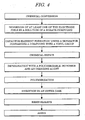
- a solid electrolytic capacitor in which a solid electrolyte layer composed of PEDT or another electroconductive polymer is formed on such a wound capacitor element is fabricated in the manner shown in FIG. 5 .
- the surface of the anode foil composed of aluminum or another valve action metal is roughened by electrochemical etching in an aqueous chloride solution, a plurality of etching pits are formed, and voltage is thereafter applied to an aqueous solution of ammonium borate or the like to form a dielectric oxide film layer (chemical conversion).
- the cathode foil is also composed of aluminum or another valve action metal, but the surface thereof is subjected to etching alone.
- the anode foil on the surface of which an oxide film layer is formed and the cathode foil on which etching pits alone are formed are wound together via an interposed separator to form a capacitor element.
- a capacitor element that has been subjected to chemical repair is sprayed with separately discharged 3,4-ethylene dioxythiophene (hereinafter referred to as EDT) or another polymerizable monomer, or is impregnated with a mixed liquid of both, and polymerization reactions are accelerated in the capacitor element to produce a solid electrolyte layer composed of PEDT or another electroconductive polymer.
- EDT 3,4-ethylene dioxythiophene
- the capacitor element is thereafter encased in a cylindrical outer case with a closed end to fabricate a solid electrolytic capacitor.
- High-melting lead-free solder has come to be used in recent years due to environmental concerns, and the solder reflow temperature has risen from a range of 200 to 220°C to a range of 230 to 270°C.
- performing solder reflow under such high temperatures has a drawback in that the withstand voltage is reduced. For this reason, a strong need exists for the development of a solid electrolytic capacitor whose withstand voltage characteristics do not degrade even when high temperature reflow soldering is carried out.
- a first object of the present invention is to provide a solid electrolytic capacitor and a manufacturing method thereof that allow the ESR to be reduced and the electrostatic capacity to be improved.
- a second object of the present invention is to provide a solid electrolytic capacitor and a manufacturing method thereof that reduce.the ESR and improve the electrostatic capacity and withstand voltage.
- a third object of the present invention is to provide a solid electrolytic capacitor and a manufacturing method thereof that can improve the yield when manufacturing high withstand voltage products.
- a fourth object of the present invention is to provide a solid electrolytic capacitor and a manufacturing method there of that can improve withstand voltage and inhibit LC fluctuation after reflow.
- Reference US 6058006 discloses an electrolytic capacitor comprising a capacitor element formed by winding an anode foil having pits with a diameter of not less than 0.1 mu m formed on the surface thereof and a cathode foil with a separator provided interposed therebetween, the separator having been coated with PVA which is then dried, the capacitor element being in contact with an electrolytic solution for electrolytic capacitor containing ethylene glycol, whereby the electrolytic solution is gelled.
- An electrolytic capacitor which comprises a capacitor element formed by winding an anode foil and a cathode foil with a separator provided interposed therebetween, the separator having been prepared by mixing filament fibers formed by extruding PVA solution into a gas, the capacitor element being impregnated with an electrolytic solution is also disclosed.
- an electrolytic capacitor which is prepared by a process which comprises impregnating a capacitor element formed by winding an anode foil, a cathode foil and a separator with a driving electrolytic solution, inserting the capacitor element into an outer case, sealing the opening of the outer case with a sealing member, and then subjecting the anode to reformation, wherein the driving electrolytic solution contains boric acid and a polyvinyl alcohol is attached to at least both the upper and lower end faces of the capacitor element, is further disclosed.
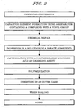
- a solid electrolytic capacitor comprising a capacitor element having an anode foil and a cathode foil wound with a separator interposed therebetween, the capacitor element being provided with a solid electrolyte layer of an electroconductive polymer, the solid electrolyte layer being composed of a polymerized mixture of a polymerizable monomer and an oxidizing agent, wherein the separator contains a compound with a vinyl group as a binder, wherein the compound with a vinyl group is preferably polyvinyl alcohol, polyvinyl acetate, polyvinyl pyrrolidone, or polyacrylamide, characterized in that (i) the capacitor element contains a conjugate composed of a borate compound and the compound with a vinyl group, or (ii) the capacitor element contains a conjugate composed of dodecylbenzenesulfonic acid and the compound with a vinyl group, or (iii) the capacitor element contains a conjugate composed of sodium naphthalenesul
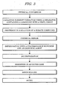
- the object of the present invention is also achieved by means of a method for manufacturing a solid electrolytic capacitor wherein an anode foil and a cathode foil are wound with a separator composed of that contains a compound with a vinyl group interposed therebetween as a binder to form a capacitor element, wherein the compound with a vinyl group is preferably polyvinyl alcohol, poly-vinyl acetate, polyvinyl pyrrolodine, or polyacrylamide, characterized in that (i) the capacitor element is impregnated with a solution of a borate compound and heated, whereby the heating temperature is preferably 120 to 250 degree Celsius, and is more preferably 150 to 200 degree Celsius, to form a conjugate composed of the bo-rate compound and the compound with a vinyl group, and a solid electrolyte layer com-prising an electroconductive polymer is formed thereafter by impregnation with a poly-merizable monomer and an oxidizing agent and polymerization thereof, or (ii) the capacitor element is impre
- the ESR is reduced and electrostatic capacity is improved by suitably adjusting the content of the compound with a vinyl group in the separator.
- the ESR can be reduced and the electrostatic capacity and withstand voltage improved by adding a predetermined coupling agent and a surfactant to the capacitor element prior to impregnation with a polymerizable monomer and oxidizing agent.
- a solid electrolytic capacitor in which a separator containing a compound with a vinyl group is used, degradation of the withstand voltage characteristics due to lead-free reflow can be prevented and the yield when manufacturing a high withstand voltage product can be improved by impregnating the capacitor element with a borate compound or another additive solution, forming a conjugate composed of a compound having a vinyl group and a borate compound or another additive, and thereafter forming a solid electrolytic layer composed of an electroconductive polymer.
- the withstand voltage is improved and LC fluctuation after reflow can be inhibited by impregnating a capacitor element with a polyimide silicon solution, and forming a film composed of polyimide silicon and a compound with a vinyl group.
- the first, second and sixth embodiment are not embodiments of the invention, but are useful for understanding it.
- the present inventors discovered that the ESR is reduced and the electrostatic capacity is improved by configuring the binder of the separator with a compound having a vinyl group, and making this binder 10 to 20% of the total weight of the separator.
- the present inventors conducted studies while varying the content of the binder composed of a compound with a vinyl group to conduct the investigation, and discovered that when the above-described range is exceeded, ESR and the electrostatic capacity characteristics are reduced, and that the characteristics remain constant when the content is less than this range.
- the method for manufacturing the solid electrolytic capacitor in the first embodiment is described below. That is, a cathode foil and an anode foil., with an oxidized film layer formed on the surface and a separator interposed therebetween, are wound together to form a capacitor element, and prior to subjecting the capacitor element to chemical repair the content of the binder in the separator is adjusted to 10 to 20% with respect to the total weight of the separator.
- the capacitor element is immersed in mixed liquid prepared by mixing a polymerizable monomer and an oxidizing agent together with a predetermined solvent, a polymerization reaction of the electroconductive polymer is induced in the capacitor element, and a solid electrolyte layer is formed.
- the capacitor element is then inserted in an outer case; sealing rubber is mounted in the open-end portion and sealed with a tightening operation; and the unit is thereafter aged to form a solid electrolytic capacitor.
- a separator for a solid electrolytic capacitor principally composed of synthetic resin - is ordinarily composed of a binder that joins the synthetic resin and other components together.
- the synthetic resin itself may be used as the binder, or the synthetic resin may be made into a fibrous form and melted in the separator fabrication process to form the main fiber.
- polyvinyl alcohol PVA
- polyvinyl acetate polyvinyl pyrrolidone
- polyacrylamide polyacrylamide
- polyester fiber or nylon fiber with excellent thermal resistance is preferred as the main fiber of the separator.
- a separator composed of vinylon fiber is not suitable because lead-free reflow characteristics cannot be satisfied.
- a separator containing 10% or more of a binder composed of a compound with a vinyl group is obtained in which the binder in the separator is dissolved with a hot water immersion treatment and adjusted to the above-described range.
- the temperature of the hot water is preferably 60 to 100°C at which PVA and the like dissolve, and the hot water immersion treatment time is preferably 5 to 180 minutes, but is more preferably 20 to 60 minutes.
- the hot water immersion treatment is preferably performed with running water because PVA or the like dissolves faster and more uniformly.
- This hot water immersion treatment is preferably performed after the capacitor element has been formed.
- the strength of the separator is reduced, so the winding strength during winding is reduced, the formation state of the electroconductive polymer in the capacitor element is worsened, and the characteristics are degraded.
- EDT is used as the polymerizable monomer
- an EDT monomer can be used as the EDT with which the capacitor element is impregnated, but a monomer solution in which EDT and a volatile solvent are mixed in a volume ratio of 1:0 to 1:3 may also be used.
- Pentane or another hydrocarbon, tetrahydrofuran or anther ether, ethyl formate or another ester, acetone or another ketone, methanol or another alcohol, or acetonitrile or another nitrogen compound may be used as the volatile solvent, but preferably used among these is methanol, ethanol, acetone, or the like.
- Ferric p-toluenesulfonate dissolved in ethanol, or an aqueous solution of periodic acid or iodic acid can be used as the oxidizing agent, and the concentration of the oxidizing agent with respect to the solvent is preferably 40 to 58 wt%, and is more preferably 45 to 57 wt%.
- the ESR decreases with increased concentration of the oxidizing agent with respect to the solvent.
- a volatile solvent used for the above-described monomer solutions may be used as the solvent for the oxidizing agent, and among these ethanol is advantageous. The reason that ethanol is advantageous as the solvent for the oxidizing agent is believed to be that the vapor pressure is low, so evaporation easily occurs, and the remaining amount is small.
- Ammonium dihydrogen phosphate, diammonium hydrogen phosphate, or another phosphate-based chemical conversion solution; ammonium borate or another boric acid-based chemical conversion solution; or ammonium adipate or another adipic acid-based chemical conversion solution may be used as the chemical conversion solution for chemical repair, but preferably used among these is ammonium dihydrogen phosphate.
- the immersion time is preferably 5 to 120 minutes.
- The' polymerizable monomer used may be, in addition to the above-described EDT, a thiophene derivative, aniline, pyrrole, furan, acetylene, or a derivative thereof other than EDT, as long as oxidation polymerization is carried out with a predetermined oxidizing agent to form a polymerizable monomer.
- a thiophene derivative aniline, pyrrole, furan, acetylene, or a derivative thereof other than EDT, as long as oxidation polymerization is carried out with a predetermined oxidizing agent to form a polymerizable monomer.
- Substances with the structural formula shown in FIG. 1 may be used for the thiophene derivative.
- the first embodiment is described next on the basis of Examples A1 to A5 and Comparative Example A1 manufactured in the manner described below.
- PET fiber was used as the main fiber, and a solid electrolytic capacitor was fabricated as follows by using a separator containing 15% of a binder composed of PVA.
- An electrode-forming device was connected to the cathode foil and anode foil on whose surface an oxide film layer had been formed, and both electrode foils were wound with the interposed separator to form a capacitor element whose element shape was 5 ⁇ ⁇ 2.8 L.
- This capacitor element was immersed for 20 minutes in hot water at a temperature of 100°C, and the binder content was adjusted to 13% after the hot water immersion treatment.
- the capacitor element was immersed for 40 minutes in ammonium dihydrogen phosphate, and chemical repair was carried out.
- EDT and an ethanol solution of 45% ferric p-toluenesulfonate were mixed in a container, the capacitor element was immersed for 10 seconds in the-mixed liquid and heated for 60 minutes at 120°C, and a PEDT polymerization reaction was induced in the capacitor element to form a solid electrolyte layer.
- the capacitor element was inserted into a cylindrical outer case with a closed end, and sealing rubber was mounted in the open-end portion and sealed with a tightening operation. Aging was thereafter carried out for 120 minutes at 150°C with an applied voltage of 8.2 V to form a solid electrolytic capacitor.
- the rated voltage of the solid electrolytic capacitor was 6.3 WV, and the rated capacity was 120 ⁇ F.
- Example A1 Using a separator containing 25% of a binder composed of PVA, a capacitor element was formed and immersed for 20 minutes in hot water at a temperature of 100°C, and after the hot water immersion treatment the binder content was adjusted to 14%. Other conditions and steps were the same as Example A1.
- Example A1 Using a separator containing 30% of a binder composed of PVA, a capacitor element was formed and immersed for 10 minutes in hot water at a temperature of 100°C, and after the hot water immersion treatment the binder content was adjusted to 20%. Other conditions and steps were the same as Example A1.
- Example A1 Using a separator containing 30% of a binder composed of PVA, a capacitor element was formed and immersed for 20 minutes in hot water at a temperature of 100°C, and after the hot water immersion treatment the binder content was adjusted to 15%. Other conditions and steps were the same as Example A1.
- the present inventors as a result of thoroughgoing research to achieve the second object, succeeded in obtaining a solid electrolytic capacitor and a manufacturing method thereof that can reduce the ESR and improve the electrostatic capacity and withstand voltage by using a separator that contains as: a binder 10 wt% or more of a compound having a vinyl group, and adding one or two compounds selected from acetylene diol and dimethyl lauryl amine oxide to the capacitor element prior to impregnation with a polymerizable monomer and an oxidant.
- the method for manufacturing the solid electrolytic capacitor in the second embodiment is described below. That is, a cathode foil and an anode foil, with an oxidized film layer-formed on the surface and a separator that contains as a binder 10 wt% or more of a compound having a vinyl group interposed therebetween, are wound together to form a capacitor element, and the capacitor element.is subjected to chemical repair.
- the capacitor element After adding to the capacitor element one or two compounds selected from acetylene diol and dimethyl lauryl amine oxide, the capacitor element is immersed in a mixed liquid of a polymerizable monomer and an oxidizing agent, and a polymerization reaction involving the electroconductive polymer is induced in the capacitor element to form a solid electrolyte layer.
- the capacitor element is then inserted in an outer case; sealing rubber is mounted in the open-end portion and sealed with a tightening operation; and the unit is thereafter aged to form a solid electrolytic capacitor.
- a separator for a solid electrolytic capacitor principally composed of synthetic resin is ordinarily composed of a binder that joins the synthetic resin and other components together.
- the synthetic resin itself may be used as the binder, or the synthetic resin may be made into a fibrous form and melted in the separator fabrication process to form the main fiber.
- Used in the present invention is a separator in which a compound with a vinyl group is used as a binder.
- polyvinyl alcohol PVA
- polyvinyl acetate polyvinyl pyrrolidone
- polyacrylamide polyacrylamide
- polyester fiber or nylon fiber with excellent thermal resistance is advantageous in that thermal resistance is improved.
- the content of the binder composed of a compound with a vinyl group is preferably 10 wt% or more with respect to the separator. When the content is less than 10 wt%, sufficient effect cannot be obtained.
- a preferred method for adding these additives to the capacitor element is to carry out chemical repair, immerse the capacitor element at normal temperature in 0.1 to 10%, and more preferably 0.5 to 2% aqueous solution, dry the capacitor element at 50 to 90°C, and thereafter carry out heating treatment at 15.0 to 200 °C. It is thought that this heating improves the bridged state of the PVA, PEDT, and surfactant, and increases the adhesiveness.
- EDT is used as the polymerizable monomer
- an EDT monomer can be used as the EDT with which the capacitor element is impregnated, but a monomer solution in which EDT and a volatile solvent are mixed at a volume ratio of 1:0 to 1:3 may also be used.
- Pentane or another hydrocarbon, tetrahydrofuran or another ether, ethyl formate or another ester, acetone or another ketone, methanol or another alcohol, or acetonitrile or another nitrogen compound may be used as the volatile solvent, but preferably used among these is methanol, ethanol, acetone, or the like.
- Ferric p-toluenesulfonate dissolved in ethanol, or an aqueous solution of periodic acid or iodic acid can be used as the oxidizing agent, but the concentration of the oxidizing agent with respect to the solvent is preferably 40 to 65 wt%, and is more preferably 45 to 57 wt%.
- the ESR decreases with increased concentration of the oxidizing agent with respect to the solvent.
- a volatile solvent used for the above-described monomer solutions may be used as the solvent for the oxidizing agent, and among these ethanol is advantageous. The reason that ethanol is advantageous as the solvent for the oxidizing agent is believed to be that the vapor pressure is low, so evaporation easily occurs, and the remaining amount is small.
- Ammonium dihydrogen phosphate, diammonium hydrogen phosphate, or another phosphate-based chemical conversion solution; ammonium borate or another boric acid-based chemical conversion solution; or ammonium adipate or another adipic acid-based chemical conversion solution may be used as the chemical conversion solution for chemical repair, but preferably used among these is ammonium dihydrogen phosphate.
- the immersion time is preferably 5 to 120 minutes.
- the polymerizable monomer used may be, in addition to the above-described EDT, a thiophene derivative, aniline, pyrrole, furan, acetylene, or a derivative thereof other than EDT, as long as oxidation polymerization is carried out with a predetermined oxidizing agent to form a polymerizable monomer.
- a thiophene derivative aniline, pyrrole, furan, acetylene, or a derivative thereof other than EDT, as long as oxidation polymerization is carried out with a predetermined oxidizing agent to form a polymerizable monomer.
- Substances with the structural formula shown in FIG. 1 may be used for the thiophene derivative.
- the reason that the ESR is reduced and an improvement in the electrostatic capacity and withstand voltage can be obtained with the configuration of the above-described second embodiment is that when PVA dissolved during chemical repair adheres to the dielectric film, additives are added thereafter, and PEDT is the formed, the adhesiveness of the PVA and PEDT is increased and the electrostatic capacity and ESR are improved.
- PVA elutes from the separator during chemical repair and the voids in the separator increase in size, so more PEDT is retained in the separator and the ESR decreases.
- the attack of the PVA deposited on the dielectric film toward the dielectric film of oxidizing agent remaining in the PEDT is reduced and the withstand voltage is increased. If the PVA content is less than 10 wt%, these effects are reduced.
- the second embodiment is described next on the basis of Examples and conventional examples manufactured in the manner described below.
- PET fiber was used as the main fiber, and a solid electrolytic capacitor was fabricated as follows by using a separator containing 10 wt% of PVA as a binder.
- An electrode-forming device was connected to the cathode foil and the anode foil on whose surface an oxide film layer had been formed, and both electrode foils were wound with the interposed separator to form a capacitor element.
- the capacitor element was immersed for 40 minutes in ammonium dihydrogen phosphate, and chemical repair was carried out. After the chemical repair, the capacitor element was dried at 100°C, immersed for three minutes at normal temperature in an aqueous solution of 1 wt% acetylene diol, dried at 60°C, and heated at 170°C.
- EDT and an ethanol solution of 45% ferric p-toluenesulfonate were mixed in a container, the capacitor element was immersed for 10 seconds in the mixed liquid and heated for 60 minutes at 120°C, and a PEDT polymerization reaction was induced in the capacitor element to form a solid electrolyte layer.
- the capacitor element was inserted into a cylindrical outer case with a closed end, and sealing rubber was mounted in the open-end portion and sealed with a tightening operation. Aging was thereafter carried out for 120 minutes at 150°C with an applied voltage of 5.2 V to form a solid electrolytic capacitor.-
- the rated voltage of the solid electrolytic capacitor was 4 WV, and the rated capacity was 180 ⁇ F.
- Example C1 Chemical repair was carried out, the capacitor element was then dried at 100°C, thereafter immersed for three minutes at normal temperature in an aqueous solution of 1 wt% dimethyl lauryl amine oxide, dried at 60°C, and heated at 170°C. Other conditions and steps were the same as Example C1.
- the present inventors arrived at the following conclusions as a result of thoroughgoing research as to the cause of the higher ratio of shorting occurrences in the aging step when manufacturing a high withstand voltage product in order to achieve the third object.
- an electroconductive polymer also present in the capacitor after the electroconductive polymer has been formed are monomers and oxidizing agents unrelated to the polymerization reaction, and other reaction residues.
- the withstand voltage of the substances other than the electroconductive polymer is lower than the withstand voltage of the electroconductive polymer, so it is thought that these substances reduce the withstand voltage of the solid electrolytic capacitor.
- the present inventors found that the withstand voltage of the solid electrolytic capacitor can be improved by forming a capacitor element using a separator containing a compound with a vinyl group and adding a borate compound to the capacitor element.
- the method for manufacturing the solid electrolytic capacitor in the third embodiment is described below. That is, a cathode foil and an anode foil, with an oxidized film layer formed on the surface and a separator containing a compound with a vinyl group interposed therebetween, are wound together to form a capacitor element, and the capacitor element is subjected to chemical repair.
- a solution of a borate compound is impregnated and heated in the capacitor element, a conjugate composed of a compound with a vinyl group and a borate compound is generated, the capacitor element is thereafter immersed in, a mixed liquid that was prepared by mixing a polymerizable monomer and an oxidizing agent together with a predetermined solvent, and a polymerization reaction involving the electroconductive polymer is induced in the capacitor element to form a solid electrolyte layer.
- the capacitor element is then inserted in an outer case; sealing rubber is mounted in the open-end portion and sealed with a tightening operation; and the unit is thereafter aged to form a solid electrolytic capacitor. It is even more advantageous to add a predetermined coupling agent to the capacitor element prior to impregnation with the polymerizable monomer and the oxidizing agent.
- a separator for a Solid electrolytic capacitor principally composed of synthetic resin is ordinarily composed of a binder that joins the synthetic resin and other components together.
- the synthetic resin itself may be used as the binder, or the synthetic resin may be made into a fibrous form and melted in the separator fabrication process to form the main fiber. Adequate results were obtained in the present invention by using a separator in which a compound with a vinyl group is used as the main fiber or binder of such a separator.
- the required amount of compound with a vinyl group that is added to the main fiber or binder of the separator may be a small amount, but the effect is not diminished with a larger amount.
- the reason for this is that the compound with a vinyl group that was added to the separator elutes and adheres to the oxide film layer, so the effect of the present invention can be obtained. Therefore, the separator may be formed with 100% vinylon fiber in the same manner as a vinylon separator. In this case, the elution amount should be controlled so that an excessive amount of compound with a vinyl group is not eluted in the manufacturing step, reducing the strength of the separator.
- a typical example of the present invention is a separator that uses a PVA binder, but in this case, the content thereof is preferably kept at 10 to 20 wt% in order to obtain a predetermined strength.
- Examples of compounds with a vinyl group that are preferably used in this case are polyvinyl alcohol (hereinafter abbreviated as PVA), polyvinyl acetate, polyvinyl pyrrolidone, and polyacrylamide, but PVA is preferred. More specifically, PVA fiber (vinylon) or undrawn vinylon may be used as the main fiber of the separator, and a PVA polymer or undrawn vinylon may be used as the binder. Vinylon fiber with a fiber diameter of 3.0 to 12.0 ⁇ m is cut into short fibers with a predetermined cut length, and, using a predetermined binder, unwoven cloth obtained with any device may be used, for example.
- Methods that may be used for adding a compound with a vinyl group to the separator include a method in which the separator is composed of the binder or main fiber as described above (that is to say, a method for adding the compounds with a vinyl group as a constituent component of the separator), a method in which the separator is immersed in a solution of the compound with a vinyl group, and a method for applying the compound with a vinyl group.
- borate compounds examples include boric-acid, borax, ammonium salt of boric acid, metal salt or another metal salt, and triethyl borate or another ester of boric acid, but boric acid is preferred.
- the solvent for these borate compounds should be one in which these compounds are dissolved, and mainly water, glycerin, or the like can be used.
- the concentration of the borate compound solution is preferably 0.1 wt% to 10 wt%, and is more preferably 3 wt% to 7 wt%.
- concentration of the borate compound solution is not in this range, the effect is reduced. This is due to the fact that when the concentration of borate compound solution is less than 0.1 wt%, the amount of conjugate formed is insufficient because the amount of borate compound in the solution is small.
- the concentration of borate compound solution is greater than. 10 wt%, the excess boric acid exerts a negative effect after the conjugate is formed, and the ESR increases.
- a method of immersing a capacitor element in the borate compound solution, or a method for discharging the borate compound solution over the capacitor element may be used for adding the borate compound to the capacitor element.
- the heating temperature is preferably 120 to 250°C, and is more preferably 150 to 200°C. When the heating temperature is not in this range, the effect is reduced.
- the present inventors thoroughly researched the timing for adding the borate compound to the capacitor element. As a result, it became apparent that the addition may be made at a stage prior to the step for forming an electroconductive polymer, or at any other stage. In other words, the timing may be prior to chemical repair, as described above, or the compound may be allowed to deposit on the electrode foils prior to forming the capacitor element, and the methods (1) to (3) described below, for example, may be considered.
- the method, in (1) corresponds to the manufacturing method described in (D-1).
- method (1) in which an anode foil and cathode foil are wound while a separator to which a compound with a vinyl group has been added is interposed therebetween to form a capacitor element, the capacitor element is subjected to chemical repair, the capacitor element is then impregnated with a solution of borate compound, a conjugate composed of a borate compound and a compound with a vinyl group is formed, and a polymerization reaction involving the electroconductive polymer is thereafter induced in the capacitor element to form a solid electrolyte layer.
- the effect of the present invention is not changed if the resin sealing is not performed with the methods described below.
- This method is carried out in the following order: chemical conversion, capacitor element formation using a separator containing a compound with a vinyl group, chemical repair, immersion in a solution of a borate compound, impregnation with a polymerizable monomer and an oxidizing agent, polymerization, insertion in an' outer case, resin sealing, and aging.
- This method is carried out in the following order: chemical conversion, capacitor element formation using a separator containing a compound with a vinyl group, immersion in a solution of a borate compound, chemical repair, impregnation with a polymerizable monomer and an oxidizing agent, polymerization, insertion in an outer case, resin sealing, and aging.
- This method is carried out in the following order: chemical conversion, immersion of at least one of the electrode foils in a solution of a borate compound (or application and drying thereafter), capacitor element formation using a separator containing a compound with a vinyl group, chemical repair, impregnation with a polymerizable monomer and an oxidizing agent, polymerization, insertion in an outer case, resin sealing, and aging.
- the concentration.of the solution of a borate compound, temperature, impregnation time, drying temperature, drying time, and other parameters in these methods are the same as described above.
- silane coupling agents titanium coupling agents, and aluminum coupling agents may be used for the coupling agent, and one, or two or more coupling agents selected from among these may be used.
- Methods that entail performing chemical repair, then immersing the capacitor element for several minutes in an aqueous solution of a coupling agent with a concentration of 0.1 to 5%, and more preferably 0.5 to 3%, removing the capacitor element from the solution, and thereafter drying the capacitor element at 50 to 100°C, may be used for adding these coupling agents to the capacitor element.
- silane coupling agents examples include:
- titanium coupling agents examples include:
- An example of the aluminum coupling agent is an acetal alkoxy aluminum diisopropylate.
- EDT is used as the polymerizable monomer
- an EDT monomer can be used as the EDT with which the capacitor element is impregnated, but a monomer solution in which EDT and' a volatile solvent are mixed at a volume ratio of 1:0 to' 1:3 may also be used.
- Pentane or another hydrocarbon, tetrahydrofuran or another ether, ethyl formate or another ester, acetone or another ketone, methanol or another alcohol, or acetonitrile or another nitrogen compound may be used as the volatile solvent, but preferably used among these is methanol, ethanol, acetone, or the like.
- Ferric p-toluenesulfonate dissolved in ethanol, or an aqueous solution of periodic acid or iodic acid can be used as the oxidizing agent, but the concentration of the oxidizing agent with respect to the solvent is preferably 40 to 57 wt%, and is more preferably 45 to 57 wt%.
- the ESR decreases with increased concentration of the oxidizing agent with respect to the solvent.
- a volatile solvent used for the above-described monomer solutions may be used as the solvent for the oxidizing agent, and among these ethanol is advantageous. The reason that ethanol is advantageous as the solvent for the oxidizing agent is believed to be that the vapor pressure is low, so evaporation easily occurs, and the remaining amount is small.
- the pressure in the polymerization step is even more preferable to reduce the pressure in the polymerization step.
- the reason for this is that when the pressure is reduced during heat polymerization, residual matter can be evaporated away together with polymerization.
- the pressure is preferably reduced to about 10 to 360 mmHg.
- the time for impregnating the capacitor element with the mixed liquid is determined by the size of the capacitor element, but 5 seconds or more is preferred for a capacitor element with a size of about ⁇ 5 ⁇ 3 L, and 10 seconds or more is preferred for a capacitor element with a size of about ⁇ 9 ⁇ 5 L. Impregnation for 5 seconds is required at minimum. There are no drawbacks to the characteristics even if impregnation is carried out over a long period of time.
- the reduced pressure conditions are the same as the reduced pressure,conditions in the above-described polymerization step.
- Ammonium dihydrogen phosphate, diammonium hydrogen phosphate, or another phosphate-based chemical conversion solution; ammonium borate or another boric acid-based chemical conversion solution; or ammonium adipate or another adipic acid-based chemical conversion solution may be used as the chemical conversion solution for chemical repair, but preferably used among these is ammonium dihydrogen phosphate.
- the immersion time is preferably 5 to 120 minutes.
- the polymerizable monomer used in the present invention may be, in addition to the above-described EDT, a thiophene derivative, aniline, pyrrole, furan, acetylene, or a derivative thereof other than EDT, as long as oxidation polymerization is carried out with a predetermined oxidizing agent to form a polymerizable monomer.
- a thiophene derivative aniline, pyrrole, furan, acetylene, or a derivative thereof other than EDT
- Substances with the structural formula shown in FIG. 1 may be used for the thiophene derivative.
- Allowing the compound with a vinyl group added to the separator to elute as in the present invention is more advantageous than adding a compound with a vinyl group to the element after formation of the capacitor element in that the conjugate with borate compound uniformly deposits on the oxide film.
- adhesion to PEDT is further enhanced by the synergistic effect with the conjugate, and the electrostatic capacity and ESR are improved.
- a solid electrolytic capacitor was fabricated as follows by using a separator containing a PVA polymer as a binder and containing 49 wt% of PET fiber as the main fiber.
- An electrode-forming device was connected to the cathode foil and the anode foil on whose surface an oxide film layer had been formed, and both electrode foils were wound with the interposed separator to form a capacitor element whose element shape was 5 ⁇ ⁇ 2.8 L.
- the capacitor element was immersed for 40 minutes in ammonium dihydrogen phosphate, and chemical repair was carried out. After the chemical repair, the capacitor element was dried at 100°C, immersed for three minutes at normal temperature in an aqueous solution of 5 wt% boric acid, and heated at 175°C.
- EDT and an ethanol solution of 45% ferric p-toluenesulfonate were mixed in a container, and the capacitor element was immersed for 10 seconds in the mixed liquid, held in a state of reduced pressure of about 250 mmHg, and subsequently heated for 60 minutes at 120°C under the same conditions.
- a PEDT polymerization reaction was induced in the capacitor element to form a solid electrolyte layer.
- the capacitor element was inserted into a cylindrical outer case with a closed end, and sealing rubber was mounted in the open-end portion and sealed with a tightening operation. Aging was thereafter carried out for 120 minutes at 150°C with an applied voltage of 33 V to form a solid electrolytic capacitor.
- the rated voltage of the solid electrolytic capacitor was 25 WV, and the rated capacity was 15 ⁇ F.
- PET fiber was used as the main fiber, and a solid electrolytic capacitors was fabricated as follows using a separator containing 10 wt% of PVA as a binder: An electrode-forming device was connected to the cathode foil and the anode foil on whose surface an oxide film layer had been formed, and both electrode foils were wound with the interposed separator to form a capacitor element.
- the capacitor element was immersed for 40 minutes in ammonium dihydrogen phosphate, and chemical repair was carried out. After the chemical repair; the capacitor element was dried at 100°C, then immersed for several minutes at normal temperature in an aqueous solution of 5 wt% boric acid, and dried for one hour at 150°C. The capacitor element was also immersed for one minute at normal temperature in an aqueous solution of 1 wt% N- ⁇ (aminoethyl) ⁇ -aminopropyl methoxy silane, and dried for one hour at 80°C.
- EDT and an ethanol solution of 45% ferric p-toluenesulfonate were mixed in a container, the capacitor element was immersed for 10 seconds in' the mixed liquid and heated for 60 minutes at 120°C, and a PEDT polymerization reaction was induced in the capacitor element to form a solid electrolyte layer.
- the capacitors element was inserted into a cylindrical outer case with a closed end, and sealing rubber was mounted in the open-end portion and sealed with a tightening operation. Aging was thereafter carried out for 120 minutes at 150°C with an applied voltage of 5.2 V to form a solid electrolytic capacitor.
- the rated voltage of the solid electrolytic capacitor was 2.5 WV, and the rated capacity was 180 ⁇ F.
- Example D1 After chemical repair, an electroconductive polymer was formed without immersing the capacitor element in an aqueous solution of boric acid Other conditions and steps were the same as Example D1.
- a separator containing 49 wt% of PET fiber as the main fiber was used and a PET polymer was used as a binder. Other conditions and steps were the same as Example D1.
- Example D1 After chemical repair, the capacitor element was immersed in aqueous solution of 5 wt% boric acid, and heating treatment was not performed. Other conditions and steps were the same as Example D1.
- the capacitor element was not immersed in an aqueous solution of boric acid or in a coupling agent, but other conditions and steps were the same as Example D2.
- Example D2 and Comparative Example D4 obtained with the above-described method were investigated, the results shown in Table 4 were obtained.
- Table 3 INITIAL CHARACTERISTICS NUMBER OF OCCURENCES OF SHORTING AFTER AGING SHORTING VOLTAGE AFTER SURGE TEST (V) CAP ( ⁇ F) ESR ( ⁇ /100kHz) EXAMPLE D1 15.3 0.045 0 52.5 COMPARATIVE EXAMPLE D1 15.0 0.050 6 51.0 COMPARATIVE EXAMPLE D2 14.2 0.055 7 51.0 COMPARATIVE EXAMPLE D3 15.1 0.047 4 51.2
- Example D1 in which a separator containing PVA polymer was used and an aqueous solution of boric acid was added to the capacitor element, the initial characteristics, the number of occurrences of shorting after the aging step, and the shorting voltage after a surge were all superior in comparison with the Comparative Examples D1 to D3.
- Comparative Example D1 in which the boric acid treatment was not performed, and Comparative Example D2, in which a separator that did not contain a compound with a vinyl group, were poor in comparison with Example D1.
- Table 4 IMMERSION IN BORIC ACID IMMERSION IN .
- Example D2 in which the capacitor element was immersed in a coupling agent, and Comparative Example D4, in which a coupling agent was not used to impregnate the capacitor element, are examined in Table 4, it is apparent that, in comparison with Comparative Example D4, the electrostatic capacity increased by 1.15 times and the ESR was reduced to about 91% in Example D2 in which a coupling agent was added.
- the shorting voltage increased 20 V when compared with the case in which a separator that does not contain PVA as a binder is used.
- the present embodiment is a modified example of the third embodiment described above.
- a capacitor element is formed using a separator containing a compound with a vinyl group, and the additive that is added to the capacitor element is dodecylbenzenesulfonic acid (DBS). It was found in this case as well that the same operation and effects as the third embodiment can be obtained.
- DBS dodecylbenzenesulfonic acid
- the method for manufacturing the solid electrolytic capacitor in the fourth embodiment is described below. That is, a cathode foil and an anode foil, with an oxidized film layer formed on the surface and as separator containing a compound with a vinyl group interposed therebetween, are wound together to form a capacitor element, and the capacitor element is subjected to chemical repair.
- a solution of dodecylbenzenesulfonic acid is impregnated in the capacitor element, a conjugate composed of a compound with a vinyl group and dodecylbenzenesulfonic acid is formed, the capacitor element is thereafter immersed in a mixed liquid that was prepared by mixing a polymerizable monomer and an oxidizing agent together with a predetermined solvent, and a polymerization reaction involving the electroconductive polymer is induced in the capacitor element to form a solid electrolyte layer.
- the capacitor element is then inserted in an outer case; sealing rubber is mounted in the open-end portion and sealed with a tightening operation; and the unit is thereafter aged to form a solid electrolytic capacitor.
- the separator used in the present embodiment is preferably the same separator that is described in the section titled "(D-2) Separator" of the third embodiment.
- Water, alcohol, or the like is preferably used as the solvent for the dodecylbenzenesulfonic acid used in the present invention.
- the concentration of the dodecylbenzenesulfonic acid is preferably 0.1 wt% to 5 wt%, and even more preferably 0.2 wt% to 2 wt%.
- concentration of the dodecylbenzenesulfonic acid solution is not in this range, the layer of the conjugate of DBS and PVA is thin, so the electrostatic capacity, improvement in the ESR characteristics, improvement in the withstand voltage, and LC suppression effect are all diminished..
- the concentration of the dodecylbenzenesulfonic acid solution exceeds this range, the layer of the conjugate of DBS and PVA is excessively thick, and the electroconductive characteristics of the layer are reduced, so the electrostatic capacity and the ESR characteristics are also diminished.
- a method of immersing a capacitor element in the dodecylbenzenesulfonic acid solution, or a method of discharging the dodecylbenzenesulfonic acid solution over the capacitor element may be used for adding the dodecylbenzenesulfonic acid to the capacitor element.
- the heating temperature is preferably 120. to 250°C, and is more preferable 150 to 200°C.
- the heating temperature is not in this range, the effect is reduced This is thought to be due to the fact that when the heating temperature is less than 120°C, the reaction that increases the hydrophobicity of the end groups of the compound with a vinyl group does not adequately progress, and when the heating temperature exceeds 250°C, the thermal degradation of the compound with a vinyl group takes place and the effect is reduced.
- the present inventors thoroughly researched the timing for adding the dodecylbenzenesulfonic acid to the capacitor element, and, as a result, it became apparent that the addition may be made at a stage prior to the step for forming an electroconductive polymer, in the same manner as the third embodiment, or at any other stage.
- the timing may be prior to chemical repair, as described above, or the compound may be allowed to deposit on the electrode foils prior to forming the capacitor element, and the methods (1) to (3) described below, for example, may be considered.
- the method in (1) corresponds to the manufacturing method described above.
- method (1) in which an anode foil and cathode foil are wound while a separator to which a compound with a vinyl group has been added is interposed therebetween to form a capacitor element, the capacitor element is subjected to chemical repair, the capacitor element is then impregnated with a solution of dodecylbenzenesulfonic acid, a conjugate composed of dodecylbenzenesulfonic acid and a compound with a vinyl group is formed, and the polymerization reaction of the electroconductive polymer is thereafter brought about in the capacitor element to form a solid electrolyte layer.
- This method is carried out in the following order: chemical conversion, capacitor element formation using a separator containing a compound with a vinyl group, chemical repair, immersion in a solution of dodecylbenzenesulfonic acid, impregnation with a polymerizable monomer and an oxidizing agent, polymerization, insertion in an outer case, resin sealing, and aging.
- This method is carried out in the following order: chemicals conversion, capacitor element formation using a separator containing a compound with a vinyl group, immersion in a solution of dodecylbenzenesulfonic acid, chemical repair, impregnation with a polymerizable monomer and an oxidizing agent, polymerization, insertion in an outer case, resin sealing, and aging.
- This method is carried out in the following order: chemical conversion, immersion of at least one of the electrode foils in a solution of dodecylbenzenesulfonic acid (or application and drying thereafter), capacitor element formation using a separator containing a compound with a vinyl group, chemical repair, impregnation with a polymerizable monomer and an oxidizing agent, polymerization, insertion in an outer case, resin sealing, and aging.
- the concentration of the solution of dodecylbenzenesulfonic acid, temperature, impregnation time, drying temperature, drying time, and other parameters in these methods are the same as described above.
- EDT is used as the polymerizable monomer
- an EDT monomer can be used as the EDT with which the capacitor element is impregnated, but a monomer solution in which EDT and a volatile solvent are mixed at a volume ratio of 1:0 to 1:3 may also be used.
- Pentane or another hydrocarbon, tetrahydrofuran or another ether, ethyl formate or another ester, acetone or another ketone, methanol or another alcohol, or acetonitrile or another nitrogen compound may be used as the volatile solvent, but preferably used among these is methanol, ethanol, acetone, or the like.
- Ferric p-toluenesulfonate dissolved in ethanol, or an aqueous solution of periodic acid or iodic acid can be used as the oxidizing agent, but the concentration of the oxidizing agent with respect to the solvent is preferably 40 to 57 wt%, and is more preferably 45 to 57 wt%.
- the ESR decreases with increased concentration of the oxidizing agent with respect to the solvent.
- a volatile solvent used for the above-described monomer solutions may be used as the solvent for the oxidizing agent, and among these ethanol is advantageous. The reason that ethanol is advantageous as the solvent for the oxidizing agent is believed to be that the vapor pressure is low, so evaporation easily occurs, and the remaining amount is small.
- the pressure in the polymerization step is even more preferable to reduce the pressure in the polymerization step.
- the reason for this is that when the pressure is reduced during heat polymerization, residual matter can be evaporated away together with polymerization.
- the pressure is preferably reduced to about 10 to 360 mmHg.
- the time for impregnating the capacitor element with the mixed liquid is determined by the size of the capacitor element, but 5 seconds or more is preferred for a capacitor element with a size of about ⁇ 5 ⁇ 3 L, and 10 seconds or more is preferred for a capacitor element with a size of about ⁇ 9 ⁇ 5 L. Impregnation for 5 seconds is required at minimum. There are no drawbacks to the characteristics even if impregnation is carried out over a long period of time.
- the reduced pressure conditions are the same as the reduced pressure conditions in the above-described polymerization step.
- Ammonium dihydrogen phosphate, diammonium hydrogen phosphate, or another phosphate-based chemical conversion solution; ammonium borate or another boric acid-based chemical conversion solution; or ammonium adipate or another adipic acid-based chemical conversion solution may be used as the chemical conversion solution for chemical repair, but preferably used among these is ammonium dihydrogen phosphate.
- the immersion time is preferably 5 to 120 minutes.
- the polymerizable monomer used in the present invention may be, in addition to the above-described EDT, a thiophene derivative, aniline, pyrrole, furan, acetylene, or a derivative thereof other than EDT, as long as oxidation polymerization is carried out with a predetermined oxidizing agent to form a polymerizable monomer.
- a thiophene derivative aniline, pyrrole, furan, acetylene, or a derivative thereof other than EDT
- Substances with the structural formula shown in FIG. 1 may be used for the thiophene derivative.
- Allowing the compound with a vinyl group added to the separator to elute as in the present invention is more advantageous than adding a compound with a vinyl group to the element after formation of the capacitor element in that the conjugate with dodecylbenzenesulfonic acid uniformly deposits on the oxide film.
- a solid electrolytic capacitor was fabricated as follows by using a separator containing a PVA polymer as a binder and containing 49 wt% of PET fiber as the main fiber.
- An electrode-forming device was connected to the cathode foil and the anode foil on whose surface an oxide film layer had been formed, and both electrode foils were wound with the interposed separator to form a capacitor element whose element shape was 7 ⁇ ⁇ 5 L.
- the capacitor element was immersed for 40 minutes in ammonium dihydrogen phosphate, and chemical repair was carried out. After the chemical repair, the capacitor element was' dried at 100°C, immersed in an aqueous solution of. 0.1 wt% dodecylbenzenesulfonic acid, and heated at 150°C.
- EDT and an ethanol solution of 45% ferric p-toluenesulfonate were mixed in a container, and the capacitor element was immersed for 10 seconds in the mixed liquid, held in a state of reduced pressure of about 250 mmHg, and subsequently heated for 60 minutes at 120°C under the same conditions.
- a PEDT polymerization reaction was induced in the capacitor element to form a solid electrolyte layer.
- the capacitor element was inserted into a cylindrical outer case with a closed end, and sealing rubber was mounted in the open-end portion and sealed with a tightening operation. Aging was thereafter carried out for 120 minutes at 150°C with an applied voltage of 33 V to form a solid electrolytic capacitor.
- the rated voltage of the solid electrolytic capacitor was 25 WV, and the rated capacity was 22 ⁇ F.
- the concentration of the dodecylbenzenesulfonic acid solution was 0.5 wt%.
- a solid electrolytic capacitor was fabricated with the other parameters the same as Example E1.
- the concentration of the dodecylbenzenesulfonic acid solution was 2.0 wt%.
- a solid electrolytic capacitor was fabricated with the other parameters the same as Example E1.
- the concentration of the dodecylbenzenesulfonic acid solution was 5.0 wt%.
- a solid electrolytic capacitor was fabricated with the other parameters the same as Example E1.
- the initial and after-reflow leakage currents decreased to 0.3 to 1.5 ⁇ A and 9 to 20 ⁇ A, respectively, while those for Comparative Example E1 were 2 ⁇ A and 30 ⁇ A.
- a solid electrolytic capacitor was fabricated as follows by using a separator containing a PVA polymer as a binder and containing 49 wt% of PET fiber as the main fiber.
- An electrode-forming device was connected to the cathode foil and the anode foil on whose surface an oxide film layer had been formed, and both electrode foils were wound with the interposed separator to form a capacitor element whose element shape was 5 ⁇ ⁇ 3 L.
- the capacitor element was immersed four 40 minutes in ammonium dihydrogen phosphate, and chemical repair was carried out. After the chemical repair, the capacitor element was dried at 100°C, immersed for three minutes at normal temperature in an aqueous solution of 0.5 wt% dodecylbenzenesulfonic acid, and heated at 150°C.
- EDT and an ethanol solution of 45% ferric p-toluenesulfonate were mixed in a container, and the capacitor element was immersed for 10 seconds in the mixed liquid, held in a state of reduced pressure of about 250 mmHg, and subsequently heated for 60 minutes at 120°C under the same conditions.
- a PEDT polymerization reaction was induced in the capacitor element to form a solid electrolyte layer.
- the capacitor element was inserted into a cylindrical outer case with a closed end, and sealing rubber was mounted in the open-end portion and sealed with a tightening operation Aging was thereafter carried out to form a solid electrolytic capacitor.
- the rated voltage of the solid electrolytic capacitor was 6.3 WV, and the rated capacity was 180 ⁇ F.
- Example E5 in which a separator containing PVA polymer was used and a dodecylbenzenesulfonic acid solution was added to the capacitor element, the results were superior in comparison with the Comparative Example E2.
- the present embodiment is a modified example of the third embodiment described above.
- a capacitor element is formed using a separator containing a compound with a vinyl group, and the additive that is added to the capacitor element is sodium naphthalenesulfonate (NPS). It was found in this case as well that the same operation and effects as the third embodiment can be obtained.
- NPS sodium naphthalenesulfonate
- the method for manufacturing the solid electrolytic capacitor in the fifth embodiment is described below. That is, a cathode foil and an anode foil, with an oxidized film layer formed on the surface and a separator containing a compound with a vinyl group interposed therebetween, are wound together to form a capacitor element, and the capacitor element is subjected to chemical repair.
- a solution of sodium naphthalenesulfonate is used to impregnate the capacitor element, a conjugate composed of a compound with a vinyl group and sodium naphthalenesulfonate is formed, the capacitor element, is thereafter immersed in a mixed liquid that was prepared by mixing a polymerizable monomer and an oxidizing agent together with a predetermined solvent, and a polymerization reaction involving the electroconductive polymer is induced in the capacitor element to form a solid electrolyte layer.
- the capacitor element is then inserted in an outer case; sealing rubber is mounted in the open-end portion and sealed with a tightening operation; and the unit is thereafter aged to form a solid electrolytic capacitor.
- the separator used in the present embodiment is preferably the same separator that is described in the section titled "(D-2) Separator" of the third embodiment.
- Water, alcohol, or the like is preferably used as the solvent for the sodium naphthalenesulfonate used in the present invention.
- the concentration of the sodium naphthalenesulfonate is preferably 0.1 wt% to 5 wt%, and even more preferably 0.2 wt% to 2 wt%.
- concentration of the sodium naphthalenesulfonate solution is not in this range, the layer of the conjugate of NPS and PVA is thin, so the electrostatic capacity, improvement in the ESR characteristics, improvement in the withstand voltage, and LC suppression effect are all diminished.
- the concentration of the sodium naphthalenesulfonate solution exceeds this range, the layer of the conjugate of NPS and PVA is excessively thick, and the electroconductive characteristics of the layer are reduced, so the electrostatic capacity and the ESR characteristics are also diminished.
- a method of immersing a capacitor element in the sodium naphthalenesulfonate solution, or a method of discharging the sodium naphthalenesulfonate solution over the capacitor element may be used for adding the sodium naphthalenesulfonate to the capacitor element.
- the heating temperature is preferably 120 to 250°C, and is more preferably 150 to 200°C. When the heating temperature is not in this range, the effect is reduced.
- the present inventors thoroughly researched the timing for adding the sodium naphthalenesulfonate to the capacitor element, and, as a result, it was apparent that the addition may be made at a stage prior to the step for forming an electroconductive polymer, in the same manner as the third embodiment, or at any other stage.
- the timing may be prior to chemical repair, as described above, or the compound may be allowed to deposit on the electrode foils prior to forming the capacitor element, and the methods (1) to (3) described below, for example, may be considered.
- the method in (1) corresponds to the manufacturing method described above.
- method (1) in which an anode foil and cathode foil are wound while a separator to which a compound with a vinyl group has been added is interposed therebetween to form a capacitor element, the capacitor element is subjected to chemical repair, the capacitor element is then impregnated with a solution of sodium naphthalenesulfonate, a conjugate composed of sodium naphthalenesulfonate and a compound with a vinyl group is formed, and the polymerization reaction of the electroconductive polymer is thereafter brought about in the capacitor element to form a solid electrolyte layer.
- This method is carried out in the following order: chemical conversion, capacitor element formation using a separator containing a compound with a vinyl group, chemical repair,' immersion in a solution of sodium naphthalenesulfonate, impregnation with a polymerizable monomer and an oxidizing agent, polymerization, insertion in an outer case, resin sealing, and aging.
- This method is carried out in the following order: chemical conversion, capacitor element formation using a separator containing a compound with a vinyl group, immersion in a solution of sodium naphthalenesulfonate, chemical repair, impregnation with a polymerizable monomer and an oxidizing agent, polymerization, insertion in an outer case, resin sealing, and aging.
- This method is carried out in the following order: chemical conversion, immersion of at least one of the electrode foils in a solution of sodium naphthalenesulfonate (or application and drying thereafter), capacitor element formation using a separator containing a compound with a vinyl group, chemical repair, impregnation with a polymerizable monomer and an oxidizing agent, polymerization, insertion in an outer case, resin sealing, and aging.
- concentration of the solution of sodium naphthalenesulfonate, temperature, impregnation time, drying temperature, drying time, and other parameters in these methods are the same as described above.
- EDT is used as the polymerizable monomer
- an EDT monomer can be used as the EDT with which the capacitor element is impregnated, but a monomer solution in which EDT and a volatile solvent are mixed at a volume ratio of 1:0 to 1:3 may also be used.
- Pentane or another hydrocarbon, tetrahydrofuran or another ether, ethyl formate or another ester, acetone or another ketone, methanol or another alcohol, or acetonitrile or another nitrogen compound may be used as the volatile solvent, but preferably used among these is methanol, ethanol, acetone, or the like.
- Ferric p-toluenesulfonate dissolved in ethanol, or an aqueous solution of periodic acid or iodic acid can be used as the oxidizing agent, but the concentration of the oxidizing agent with respect to the solvent is preferably 40 to 57 wt%, and is more preferably 45 to 57 wt%.
- the ESR decreases with increased concentration of the oxidizing agent with respect to the solvent.
- a volatile solvent used for the above-described monomer solutions may be used as the solvent for the oxidizing agent, and among these ethanol is advantageous. The reason that ethanol is advantageous as the solvent for the oxidizing agent is believed to be that the vapor pressure is low, so evaporation easily occurs, and the remaining amount is small.
- the pressure in the polymerization step is even more preferable to reduce the pressure in the polymerization step.
- the reason for this is that when the pressure is reduced during heat polymerization, residual matter can be evaporated away together with polymerization.
- the pressure is preferably reduced to about 10 to 360 mmHg.
- the time for impregnating the capacitor element with the mixed liquid is determined by the size of the capacitor element, but 5 seconds or more is preferred for a capacitor element with a size of about ⁇ 5 ⁇ 3 L, and 10 seconds or more is preferred for a capacitor element with a size of about ⁇ 9 ⁇ 5 L. Impregnation for 5 seconds is required at minimum. There are no drawbacks to the characteristics even if impregnation is carried out over a long period of time.
- the reduced pressure conditions are the same as the reduced pressure conditions in the above-described polymerization step.
- Ammonium dihydrogen phosphate, diammonium hydrogen phosphate, or another phosphate-based chemical conversion solution; ammonium borate or another boric acid-based chemical conversion solution; or ammonium adipate or another adipic acid-based chemical conversion solution may be used as the chemical conversion solution for chemical repair, but preferably used among these is ammonium dihydrogen phosphate.
- the immersion time is preferably 5 to 120 minutes.
- the polymerizable monomer used in the present invention may be, in addition to the above-described EDT, a thiophene derivative, aniline, pyrrole, furan, acetylene, or a derivative thereof other than EDT, as long as oxidation polymerization is carried out with a predetermined oxidizing agent to form a polymerizable monomer.
- a thiophene derivative aniline, pyrrole, furan, acetylene, or a derivative thereof other than EDT
- Substances with the structural formula shown in FIG. 1 may be used for the thiophene derivative.
- Allowing the compound with a vinyl group added to the separator to elute as in the present invention is more advantageous than adding a compound with a vinyl group to the element after formation of the capacitor element in that the conjugate with sodium naphthalenesulfonate uniformly deposits on the oxide film.
- a solid electrolytic capacitor was fabricated as follows by using a separator containing PVA polymer as a binder and containing 49 wt% of PET fiber as the main fiber.
- An electrode-forming device was connected to the cathode foil and the anode foil on whose surface an oxide film layer had been formed, and both electrode foils were wound with the interposed separator to form a capacitor element whose element shape was 7 ⁇ ⁇ 5 L.
- the capacitor element was immersed for 40 minutes in ammonium dihydrogen phosphate, and chemical repair was carried out. After the chemical repair, the capacitor element was dried at 100°C, immersed for three minutes at normal temperature in an aqueous solution of 0.1-wt% sodium naphthalenesulfonate, and heated at 150°C.
- EDT and an ethanol solution of 45% ferric p-toluenesulfonate were mixed in a container, and the capacitor element was immersed for 10 seconds in the mixed liquid, held in a state of reduced pressure of about 250 mmHg, and subsequently heated for 60 minutes at 120°C under the same conditions.
- a PEDT polymerization reaction was induced in the capacitor element to form a solid electrolyte layer.
- the capacitor element was inserted into a cylindrical outer case with a closed end, and sealing rubber was mounted in the open-end portion and sealed with a tightening operation. Aging was thereafter carried out for 120 minutes at 150°C with an applied voltage of 33 V to form a solid electrolytic capacitor.
- the rated voltage of the solid electrolytic capacitor was 25 WV, and the rated capacity was 22 ⁇ F.
- the concentration of the sodium naphthalenesulfonate solution was 0.5 wt%.
- a solid electrolytic capacitor was fabricated with the other parameters the same as Example F1.
- the concentration of the sodium naphthalenesulfonate solution was 2.0 wt%.
- a solid electrolytic capacitor was fabricated with the other parameters the same as Example F1.
- the concentration of the sodium naphthalenesulfonate solution was 5.0 wt%.
- a solid electrolytic capacitor was fabricated with the other parameters the same as Example F1.
- the initial and after-reflow leakage currents decreased to 0.1 to 0.5 ⁇ A and 8 to 20 ⁇ A, respectively, while those for Comparative Example F1 were 2 ⁇ A and 30 ⁇ A.
- the present inventors as a result of thoroughgoing research to achieve the fourth object described above, which is to improve the withstand voltage of a solid electrolytic capacitor and to inhibit LC fluctuation after reflow, perfected the invention described in the sixth embodiment. Specifically, the inventors focused on the mechanism of electrical conductivity and studied electrical conductivity in electroconductive polymers and other solid polymers.
- Electron emission is commonly largely divided into two types: emission by tunneling electrons and emission by electrons that pass over (passage of electrons that does not depend on film damage) the potential barrier, and it is possible that the leakage current in the solid electrolytic capacitor is caused by electrons that pass over the potential barrier, rather than being a result of a shorted condition.
- the causes of an increase in LC after re-flowing are mechanical stress (physical stress) caused by the generation of gas during re-flowing, and chemical stress (attack of the oxidizing agent, passage of electrons, or the like).
- the method for manufacturing the solid electrolytic capacitor in the sixth embodiment is described below. That is, a cathode foil and an anode foil, with an oxidized film layer formed on the surface and a separator containing a compound with a vinyl group interposed therebetween, are wound together to form a capacitor element, and the capacitor element is subjected to chemical repair.
- the capacitor element is thereafter immersed in a solution in which polyimide silicon has been dissolved with a ketone-based solvent to a concentration of 10 wt% or less, preferably 1.5 to 9 wt%, and more preferably 5 to 8 wt%.
- the capacitor element is removed, the solvent is evaporated at 40 to 100°C, and the capacitor element is then subjected to heat treatment at 150 to 200°C.
- the capacitor element is immersed in a mixed liquid of a polymerizable monomer and an oxidizing agent, and a polymerization reaction involving the electroconductive polymer is induced in the capacitor element to form a solid electrolyte layer.
- the capacitor element is then housed in an outer case, and the open-end portion is sealed with sealing rubber to form a solid electrolytic capacitor.
- the solvent that is used to dissolve polyimide silicon is preferably a ketone-based solvent which has good solubility for polyimide silicon, and cyclohexanone, acetone, methyl ethyl ketone, or the like may be used.
- the concentration of the polyimide silicon is preferably 10 wt% or less, is more preferably 1.5 to 9 wt%, and is even more preferably 5 to 8 wt%.
- concentration of the polyimide silicon is less than this range, the withstand voltage is insufficient; and when the concentration exceeds this range the electrostatic capacity decreases.
- the separator used in the present embodiment is preferably the same separator that is described in the section titled "(D-2) Separator" of the third embodiment.
- EDT is used as the polymerizable monomer
- an EDT monomer can be used as the EDT with which the capacitor element is impregnated, but a monomer solution in which EDT and a volatile solvent are mixed at a volume ratio of 1:0 to 1:3 may also be used'.
- Pentane or another hydrocarbon, tetrahydrofuran or another ether, ethyl formate or another ester, acetone or another ketone, methanol or another alcohol, or acetonitrile or another nitrogen compound may be used as the volatile solvent, but preferably used among these is methanol, ethanol, acetone, or the like.
- Ferric p-toluenesulfonate dissolved in ethanol, or an aqueous solution of periodic acid or iodic acid can be used as the oxidizing agent, but the concentration of the oxidizing agent with respect to the solvent is preferably 40 to 65 wt%, and is' more preferably 45 to 57 wt%.
- the ESR decreases with increased concentration of the oxidizing agent with respect to the solvent.
- a volatile solvent used for the above-described monomer solutions may be used as the solvent for the oxidizing agent, and among these ethanol is advantageous. The reason that ethanol is advantageous as the solvent for the oxidizing agent is believed to be that the vapor pressure is low, so evaporation easily occurs, and the remaining amount is small.
- Ammonium dihydrogen phosphate, diammonium hydrogen phosphate, or another phosphate-based chemical conversion solution; ammonium borate or another boric acid-based chemical conversion solution; or ammonium adipate or another adipic acid-based chemical conversion solution may be used as the Chemical conversion solution for chemical repair, but preferably used among these is ammonium dihydrogen phosphate.
- the immersion time is preferably 5 to 120 minutes.
- the polymerizable monomer used may be, in addition to the above-described EDT, a thiophene derivative, aniline, pyrrole, furan, acetylene, or a derivative thereof other than EDT, as long as oxidation polymerization is carried out with a predetermined oxidizing agent to form a polymerizable monomer.
- a thiophene derivative aniline, pyrrole, furan, acetylene, or a derivative thereof other than EDT, as long as oxidation polymerization is carried out with a predetermined oxidizing agent to form a polymerizable monomer.
- Substances with the structural formula shown in FIG. 1 may be used for the thiophene derivative.
- a film that prevents electrons form passing over the potential barrier and that comprises a PVA layer and a polyimide silicon layer is formed on the surface of the oxide film by immersing the capacitor element in a polyimide silicon solution after chemical repair.
- This electron-blocking layer improves the withstand voltage, prevents the attack of the oxidizing agent on the foil, and reduces the initial LC.
- the effect of inhibiting an increase in LC during reflow can be obtained with a covering of Tabcoat. It is possible to control the withstand voltage by making the electrostatic capacity and ESR largely unaffected by other factors and controlling the thickness of this electron-blocking layer.
- the VF of foil currently used can be reduced, so solid electrolytic capacitors can be made smaller, the capacity increased, and other beneficial effects obtained.
- a solid electrolytic capacitor was fabricated as follows by using a separator containing PVA polymer as a binder and containing 49 wt% of PET fiber as the main fiber.
- An electrode-forming device was connected to the cathode foil and the anode foil on whose surface an oxide film layer had been formed, and both electrode foils were wound with the interposed separator to form a capacitor element whose element shape was 7 ⁇ ⁇ 5 L.
- the capacitor element was immersed for 40 minutes in ammonium dihydrogen phosphate, and chemical repair was carried out.
- the capacitor element was then immersed in a 2 wt% cyclohexanone solution of polyimide silicon, removed, and thereafter heated for one hour at 170°C.
- EDT and an ethanol solution of 40 wt% ferric p-toluenesulfonate were mixed in a container, the solution was injected so as to achieve a weight ratio of 1:3 to prepare a mixed liquid, and the capacitor element was immersed for 10 seconds in the mixed liquid to impregnate EDT and an oxidizing agent in the capacitor element.
- the capacitor element was then left for one hour in a thermostat at 120°C, and a PEDT polymerization reaction was induced in the capacitor element to form a solid electrolyte layer.
- the capacitor element was thereafter housed in a cylindrical aluminum case with a closed end, sealed with sealing rubber to form a solid electrolytic capacitor:
- a capacitor element was immersed in 6 wt% cyclohexanone solution of polyimide silicon, then removed, and subjected to heat treatment for one hour at 170°C.
- a solid electrolytic capacitor was fabricated with the other parameters the same as Example G1.
- a capacitor element was immersed in 10 wt% cyclohexanone solution of polyimide silicon, then removed, and subjected to heat treatment for one hour at 170°C.
- a solid electrolytic capacitor was fabricated with the other parameters the same as Example G1.
- the capacitor element was not immersed in a cyclohexanone solution of polyimide silicon, and a solid electrolytic capacitor was fabricated with the other parameters the same as Example G1
- a solid electrolytic capacitor and a manufacturing method thereof can be provided in which it is possible to reduce the ESR-and to improve the electrostatic capacity.
- a solid electrolytic capacitor and a manufacturing method thereof can be provided in which it is possible to reduce the ESR and to improve the electrostatic capacity and withstand voltage by using a separator containing 10 wt% or more of a compound with a vinyl group as a binder, and adding one or two compounds selected from acetylene diol and dimethyl lauryl amine oxide to the capacitor element prior to impregnation with a polymerizable monomer and an oxidizing agent.
- a solid electrolytic capacitor with adequate initial characteristics can be provided in which a degradation of the withstand voltage characteristics due to re-flowing can be prevented, and the yield when manufacturing a high withstand voltage product can improved, and also to provide a method for manufacturing this capacitor.
- a solid electrolytic capacitor and a manufacturing method thereof can be provided in which the withstand voltage is improved and LC fluctuation after re-flowing is inhibited.
Landscapes
- Engineering & Computer Science (AREA)
- Power Engineering (AREA)
- Chemical & Material Sciences (AREA)
- Chemical Kinetics & Catalysis (AREA)
- Electrochemistry (AREA)
- Microelectronics & Electronic Packaging (AREA)
- Manufacturing & Machinery (AREA)
- Polyoxymethylene Polymers And Polymers With Carbon-To-Carbon Bonds (AREA)
Claims (13)
- Festkörperelektrolytkondensator, umfassend ein Kondensatorelement mit einer Anodenfolie und einer Kathodenfolie, die mit einem dazwischen eingeschobenen Trennelement gewickelt sind,
wobei das Kondensatorelement mit einer Festkörperelektrolytschicht eines elektrisch leitenden Polymers versehen ist, wobei die Festkörperelektrolytschicht gebildet wird aus einem polymerisierten Gemisch eines polymerisierbaren Monomers und eines Oxidationsmittels,
wobei das Trennelement eine Verbindung mit einer Vinylgruppe als Binder enthält, wobei die Verbindung mit der Vinylgruppe vorzugsweise Polyvinylalkohol, Polyvinylacetat, Polyvinylpyrrolidon oder Polyacrylamid ist,
dadurch gekennzeichnet, dass(i) das Kondensatorelement ein Konjugat enthält, das gebildet ist aus einer Boratverbindung und der Verbindung mit einer Vinylgruppe, oder(ii) das Kondensatorelement ein Konjugat enthält, das gebildet ist aus Dodecylbenzolsulfonsäure und der Verbindung mit einer Vinylgruppe, oder(iii) das Kondensatorelement ein Konjugat enthält, das gebildet ist aus Natriumnaphtalinsulfonat und der Verbindung mit einer Vinylgruppe. - Festkörperelektrolytkondensator nach Anspruch 1, dadurch gekennzeichnet, dass die Boratverbindung Borsäure oder Borax ist.
- Festkörperelektrolytkondensator nach Anspruch 1, dadurch gekennzeichnet, dass das Kondensatorelement ein Konjugat enthält, das gebildet ist aus einer Boratverbindung und der Verbindung mit einer Vinylgruppe und einem vorgegebenen Haftvermittlerzusatz,
und dass das Trennelement als Binder 10 Gew% oder mehr einer Verbindung mit einer Vinylgruppe enthält, wobei die Verbindung mit einer Vinylgruppe vorzugsweise Polyvinylalkohol, Polyvinylacetat, Polyvinylpyrrolidon oder Polyacrylamid ist und wobei das Trennelement imprägniert ist mit einem polymerisierten Gemisch des polymerisierbaren Monomers und des Oxidationsmittels. - Festkörperelektrolytkondensator nach Anspruch 3, dadurch gekennzeichnet, dass der Haftvermittler ausgewählt ist aus einem oder mehreren Elementen der Gruppe bestehend aus einem Silanhaftvermittler, einem Titanhaftvermittler und einem Aluminiumhaftvermittler.
- Festkörperelektrolytkondensator nach einem der vorangegangenen Ansprüche, dadurch gekennzeichnet, dass die Verbindung mit der Vinylgruppe Polyvinylalkohol ist.
- Festkörperelektrolytkondensator nach einem der vorangegangenen Ansprüche, dadurch gekennzeichnet, dass das polymerisierbare Monomer ein Thiophenderivat ist.
- Festkörperelektrolyt-Kondensator nach Anspruch 6, dadurch gekennzeichnet, dass das Thiophenderivat 3,4-Ethylendioxythiophen ist.
- Verfahren zum Herstellen eines Festkörperelektrolytkondensators, wobei eine Anodenfolie und eine Kathodenfolie mit einem Trennelement, das eine Verbindung mit einer Vinylgruppe enthält und als Binder dazwischen eingeschoben ist, gewickelt werden, um ein Kondensatorelement zu bilden, wobei die Verbindung mit einer Vinylgruppe vorzugsweise Polyvinylalkohol, Polyvinylacetat, Polyvinylpyrrolidon oder Polyacrylamid ist,
dadurch gekennzeichnet, dass(i) das Kondensatorelement mit einer Lösung einer Boratverbindung imprägniert und erhitzt wird, um ein Konjugat der Boratverbindung und der Verbindung mit der Vinylgruppe zu bilden, wobei die Heiztemperatur bevorzugt 120-250°C und besonders bevorzugt 150-200°C beträgt, und dass nachfolgend eine Festkörperlelektrolyt-Schicht, die ein elektrisch leitendes Polymer umfasst, durch Imprägnierung mit einem polymerisierbaren Monomer und einem Oxidationsmittel sowie einer Polymerisation hiervon gebildet wird, oder(ii) das Kondensatorelement mit einer Lösung aus Dodecylbenzolsulfonsäure imprägniert wird, um ein Konjugat zu bilden, das gebildet ist aus der Dodecylbenzolsulfonsäure und der Verbindung mit der Vinylgruppe, und dass nachfolgend eine Festkörperelektrolytschicht eines elektrisch leitenden Polymers durch Imprägnierung mit einem polymerisierbaren Monomer und einem Oxidationsmittel sowie einer Polymerisation hiervon gebildet wird, oder(iii) das Kondensatorelement mit einer Lösung aus Natriumnaphtalinsulfonat imprägniert wird um ein Konjugat zu bilden, das aus dem Natriumnaphtalinsulfonat und der Verbindung mit einer Vinylgruppe gebildet ist, und dass nachfolgend eine Festkörperelektrolyt-Schicht, die einen elektrisch leitenden Polymer enthält, durch Imprägnierung mit einem polymerisierbaren Monomer und einem Oxidationsmittel sowie einer Polymerisation hiervon gebildet wird. - Das Verfahren zum Herstellen des Festkörperelektrolytkondensators nach Anspruch 8, dadurch gekennzeichnet durch, dass
das Kondensatorelement mit einer Lösung einer Boratverbindung imprägniert und erhitzt wird, um ein Konjugat zu bilden, das aus der Boratverbindung und der Verbindung mit einer Vinylgruppe gebildet ist, wobei die Heiztemperatur bevorzugt 120-250°C und besonders bevorzugt 150-200°C beträgt und wobei die Verbindung mit einer Vinylgruppe vorzugsweise Polyvinylalkohol, Polyvinylacetat, Polyvinylpyrrolidon oder Polyacrylamid ist, und dass nachfolgend eine Festkörperelektrolytschicht, die ein elektrisch leitendes Polymer umfasst, durch Imprägnierung mit einem polymerisierbaren Monomer und einem Oxidationsmittel sowie einer Polymerisation hiervon gebildet wird, und
ein Trennelement, das als Binder 10 Gew-% oder mehr einer Verbindung mit einer Vinylgruppe enthält, als Trennelement verwendet wird, und dass ein vorgegebener Haftvermittler dem Kondensatorelement vor Imprägnierung mit dem polymerisierbaren Monomer und den Oxidationsmittel beigefügt wird. - Verfahren zum Herstellen eines Festkörperelektrolytkondensators nach Anspruch 9, dadurch gekennzeichnet, dass der Haftvermittler ausgewählt ist aus einem oder mehreren Elementen der Gruppe bestehend aus einem Silanhaftvermittler, einem Titanhaftvermittler und einem Aluminiumhaftvermittler.
- Verfahren zum Herstellen eines Festkörperelektrolyt-Kondensator nach einem der Ansprüche 8-10, dadurch gekennzeichnet, dass die Verbindung mit einer Vinylgruppe Polyvinylalkohol ist.
- Verfahren zum Herstellen eines Festkörperelektrolyt-Kondensators nach einem der Ansprüche 8-11, dadurch gekennzeichnet, dass das polymerisierbare Monomer ein Thiophenderivat ist.
- Das Verfahren zum Herstellen eines Festkörperelektrolyt-Kondensators nach Anspruch 12, dadurch gekennzeichnet, dass das Thiophenderivat 3,4- Ethylendioxythiophen ist.
Applications Claiming Priority (7)
| Application Number | Priority Date | Filing Date | Title |
|---|---|---|---|
| JP2002092614 | 2002-03-28 | ||
| JP2002092614 | 2002-03-28 | ||
| JP2002286213 | 2002-09-30 | ||
| JP2002286210 | 2002-09-30 | ||
| JP2002286213 | 2002-09-30 | ||
| JP2002286210 | 2002-09-30 | ||
| PCT/JP2003/004025 WO2003088287A1 (fr) | 2002-03-28 | 2003-03-28 | Condensateur electrolytique solide et son procede de fabrication |
Publications (3)
| Publication Number | Publication Date |
|---|---|
| EP1501107A1 EP1501107A1 (de) | 2005-01-26 |
| EP1501107A4 EP1501107A4 (de) | 2006-05-24 |
| EP1501107B1 true EP1501107B1 (de) | 2013-01-09 |
Family
ID=29255085
Family Applications (1)
| Application Number | Title | Priority Date | Filing Date |
|---|---|---|---|
| EP03746413A Expired - Lifetime EP1501107B1 (de) | 2002-03-28 | 2003-03-28 | Festelektrolytkondensator und prozess zu seiner herstellung |
Country Status (6)
| Country | Link |
|---|---|
| US (3) | US7027292B2 (de) |
| EP (1) | EP1501107B1 (de) |
| JP (2) | JP4921696B2 (de) |
| KR (1) | KR100986888B1 (de) |
| CN (1) | CN101853739B (de) |
| WO (1) | WO2003088287A1 (de) |
Families Citing this family (26)
| Publication number | Priority date | Publication date | Assignee | Title |
|---|---|---|---|---|
| KR100986888B1 (ko) * | 2002-03-28 | 2010-10-08 | 닛뽄 케미콘 가부시끼가이샤 | 고체 전해 콘덴서 및 그 제조 방법 |
| EP1551043B1 (de) * | 2002-09-30 | 2009-06-03 | Nippon Chemi-Con Corporation | Festelektrolytkondensator |
| DE102006002797A1 (de) * | 2006-01-20 | 2007-08-02 | H. C. Starck Gmbh & Co. Kg | Verfahren zur Herstellung von Polythiophenen |
| KR100784922B1 (ko) * | 2006-03-24 | 2007-12-11 | 주식회사 에너솔 | 전도성 고분자를 적용한 권취형 전해 콘덴서의 제조 방법 |
| US7460358B2 (en) * | 2007-03-21 | 2008-12-02 | Avx Corporation | Solid electrolytic capacitor containing a protective adhesive layer |
| US7483259B2 (en) * | 2007-03-21 | 2009-01-27 | Avx Corporation | Solid electrolytic capacitor containing a barrier layer |
| US7515396B2 (en) * | 2007-03-21 | 2009-04-07 | Avx Corporation | Solid electrolytic capacitor containing a conductive polymer |
| US7754276B2 (en) * | 2007-04-16 | 2010-07-13 | Kemet Electronics Corporation | Process for manufacturing low ESR conductive polymer based solid electrolytic capacitors |
| DE102007041722A1 (de) * | 2007-09-04 | 2009-03-05 | H.C. Starck Gmbh | Verfahren zur Herstellung von leitfähigen Polymeren |
| DE102008005568A1 (de) * | 2008-01-22 | 2009-07-23 | H.C. Starck Gmbh | Verfahren zur Herstellung von leitfähigen Polymeren |
| JP5340872B2 (ja) * | 2008-11-05 | 2013-11-13 | 三洋電機株式会社 | 固体電解コンデンサの製造方法 |
| US8828261B2 (en) * | 2009-11-26 | 2014-09-09 | Panasonic Corporation | Electrolytic solution for aluminum electrolytic capacitor, and aluminum electrolytic capacitor using same |
| JP5528877B2 (ja) * | 2010-03-26 | 2014-06-25 | 三洋電機株式会社 | 電解コンデンサの製造方法 |
| US8102642B2 (en) * | 2010-08-06 | 2012-01-24 | International Battery, Inc. | Large format ultracapacitors and method of assembly |
| JP2012191178A (ja) * | 2011-02-22 | 2012-10-04 | Sanyo Electric Co Ltd | 電解コンデンサおよび電解コンデンサの製造方法 |
| JP5895177B2 (ja) * | 2011-02-25 | 2016-03-30 | パナソニックIpマネジメント株式会社 | 固体電解コンデンサ及びその製造方法 |
| CN102270535B (zh) * | 2011-05-13 | 2013-10-23 | 株洲宏达电子有限公司 | 一种两步法pedt阴极片式钽电解电容器制造方法 |
| TWI464934B (zh) * | 2011-12-30 | 2014-12-11 | Eternal Materials Co Ltd | 電解質材料調配物、由此形成之電解質材料聚合物及其用途 |
| US9362057B2 (en) | 2012-07-26 | 2016-06-07 | Industrial Technology Research Institute | Electrolyte mixture for electrolytic capacitor, composition for conductive polymer synthesis and conductive polymer solid electrolytic capacitor formed by using the same |
| CN104681286B (zh) * | 2013-11-29 | 2017-08-25 | 赣州市柏瑞凯电子科技有限公司 | 导电聚合物电解质铝电容器制造方法 |
| TWI483274B (zh) | 2013-12-30 | 2015-05-01 | Ind Tech Res Inst | 複合電極及電解電容器 |
| JP2020053575A (ja) * | 2018-09-27 | 2020-04-02 | カーリットホールディングス株式会社 | 固体電解コンデンサの製造方法 |
| US11270847B1 (en) | 2019-05-17 | 2022-03-08 | KYOCERA AVX Components Corporation | Solid electrolytic capacitor with improved leakage current |
| US20210094226A1 (en) * | 2019-09-26 | 2021-04-01 | The Curators Of The University Of Missouri | Oxidation polymerization additive manufacturing |
| KR102214731B1 (ko) | 2020-09-16 | 2021-02-10 | 대신아이브(주) | 실내 공기정화 및 유해 바이러스 살균시스템 |
| KR102246239B1 (ko) | 2020-09-28 | 2021-04-29 | 대신아이브(주) | 대형공간 실내 공기정화 및 유해 바이러스 살균시스템 |
Family Cites Families (17)
| Publication number | Priority date | Publication date | Assignee | Title |
|---|---|---|---|---|
| DE3814730A1 (de) * | 1988-04-30 | 1989-11-09 | Bayer Ag | Feststoff-elektrolyte und diese enthaltende elektrolyt-kondensatoren |
| JP2735620B2 (ja) | 1989-05-29 | 1998-04-02 | 日本ケミコン株式会社 | 固体電解コンデンサ |
| JPH0458508A (ja) | 1990-06-28 | 1992-02-25 | Nippon Chemicon Corp | 電解コンデンサ |
| JPH0722285A (ja) * | 1993-06-22 | 1995-01-24 | Matsushita Electric Ind Co Ltd | 固体電解コンデンサの製造方法 |
| JP3319501B2 (ja) * | 1997-06-06 | 2002-09-03 | 日本ケミコン株式会社 | 固体電解コンデンサおよびその製造方法 |
| EP0907191B1 (de) | 1997-10-03 | 2006-10-04 | Nippon Chemi-Con Corporation | Elektrolytkondensator |
| JPH11283874A (ja) * | 1998-01-28 | 1999-10-15 | Matsushita Electric Ind Co Ltd | 電解コンデンサ |
| JPH11307396A (ja) * | 1998-04-17 | 1999-11-05 | Matsushita Electric Ind Co Ltd | 固体電解コンデンサの製造方法 |
| DE69936537T2 (de) * | 1998-09-30 | 2008-03-13 | Nippon Chemi-Con Corp., Ome | Festkörperelektrolyt-kondensator und dessen herstellungsverfahren |
| WO2001020625A1 (en) * | 1999-09-10 | 2001-03-22 | Matsushita Electric Industrial Co., Ltd. | Solid electrolytic capacitor and production method thereof, and conductive polymer polymerizing oxidizing agent solution |
| US6602741B1 (en) * | 1999-09-14 | 2003-08-05 | Matsushita Electric Industrial Co., Ltd. | Conductive composition precursor, conductive composition, solid electrolytic capacitor, and their manufacturing method |
| JP2002008946A (ja) * | 2000-06-23 | 2002-01-11 | Matsushita Electric Ind Co Ltd | 固体電解コンデンサの製造方法 |
| JP2001326145A (ja) * | 2000-05-16 | 2001-11-22 | Matsushita Electric Ind Co Ltd | コンデンサ及びその製造方法 |
| JP4568947B2 (ja) * | 2000-03-29 | 2010-10-27 | 日本ケミコン株式会社 | 固体電解コンデンサの製造方法 |
| JP2002015955A (ja) * | 2000-06-29 | 2002-01-18 | Nippon Kodoshi Corp | 電解コンデンサ |
| JP2002110466A (ja) * | 2000-09-29 | 2002-04-12 | Nippon Chemicon Corp | 固体電解コンデンサとその製造方法 |
| KR100986888B1 (ko) * | 2002-03-28 | 2010-10-08 | 닛뽄 케미콘 가부시끼가이샤 | 고체 전해 콘덴서 및 그 제조 방법 |
-
2003
- 2003-03-28 KR KR1020047015424A patent/KR100986888B1/ko not_active Expired - Fee Related
- 2003-03-28 JP JP2003585126A patent/JP4921696B2/ja not_active Expired - Fee Related
- 2003-03-28 CN CN2010100014400A patent/CN101853739B/zh not_active Expired - Lifetime
- 2003-03-28 US US10/509,550 patent/US7027292B2/en not_active Expired - Lifetime
- 2003-03-28 WO PCT/JP2003/004025 patent/WO2003088287A1/ja not_active Ceased
- 2003-03-28 EP EP03746413A patent/EP1501107B1/de not_active Expired - Lifetime
-
2006
- 2006-02-03 US US11/347,714 patent/US7116549B2/en not_active Expired - Lifetime
- 2006-02-03 US US11/347,713 patent/US7166138B2/en not_active Expired - Lifetime
-
2009
- 2009-09-16 JP JP2009214976A patent/JP4525840B2/ja not_active Expired - Fee Related
Also Published As
| Publication number | Publication date |
|---|---|
| CN101853739B (zh) | 2012-05-09 |
| JP4921696B2 (ja) | 2012-04-25 |
| JP2009296009A (ja) | 2009-12-17 |
| US7027292B2 (en) | 2006-04-11 |
| KR100986888B1 (ko) | 2010-10-08 |
| EP1501107A1 (de) | 2005-01-26 |
| US7166138B2 (en) | 2007-01-23 |
| JP4525840B2 (ja) | 2010-08-18 |
| KR20040095345A (ko) | 2004-11-12 |
| WO2003088287A1 (fr) | 2003-10-23 |
| US20060050469A1 (en) | 2006-03-09 |
| US7116549B2 (en) | 2006-10-03 |
| JPWO2003088287A1 (ja) | 2005-08-25 |
| EP1501107A4 (de) | 2006-05-24 |
| US20060139852A1 (en) | 2006-06-29 |
| US20060126271A1 (en) | 2006-06-15 |
| CN101853739A (zh) | 2010-10-06 |
Similar Documents
| Publication | Publication Date | Title |
|---|---|---|
| EP1501107B1 (de) | Festelektrolytkondensator und prozess zu seiner herstellung | |
| US8810997B2 (en) | Solid electrolytic capacitor and method of manufacturing thereof | |
| EP0617442B1 (de) | Festelektrolytkondensator und dessen Herstellungsverfahren | |
| KR20080086368A (ko) | 전도성 중합체를 함유하는 고체 전해질 축전기 | |
| EP1158551B1 (de) | Festelektrolytkondensator und Verfahren zu seiner Herstellung | |
| KR101018184B1 (ko) | 고체 전해 콘덴서의 제조 방법 | |
| CN112735834B (zh) | 一种新型固态铝电解电容器及其制备方法 | |
| JP4442288B2 (ja) | 固体電解コンデンサの製造方法 | |
| JP7067598B2 (ja) | 固体電解コンデンサ及びその製造方法 | |
| CN113257577B (zh) | 一种高温后esr上升率低的固液混合电解电容器的制备方法 | |
| CN112582175B (zh) | 一种固态铝电解电容器及其制备方法 | |
| CN100590760C (zh) | 固体电解电容器及其制造方法 | |
| JP2022100375A (ja) | 固体電解コンデンサ及びその製造方法 | |
| JP4780893B2 (ja) | 固体電解コンデンサ | |
| JP2001284178A (ja) | 固体電解コンデンサとその製造方法 | |
| JP2003100557A (ja) | 固体電解コンデンサ及びその製造方法 | |
| JP4639504B2 (ja) | 固体電解コンデンサの製造方法 | |
| JP4646462B2 (ja) | 電解コンデンサ | |
| JP2003289019A (ja) | 固体電解コンデンサの製造方法 | |
| JP2001284179A (ja) | 固体電解コンデンサとその製造方法 | |
| JP2002299170A (ja) | 固体電解コンデンサの製造方法及び固体電解コンデンサ | |
| JP2005109075A (ja) | 固体電解コンデンサの製造方法 |
Legal Events
| Date | Code | Title | Description |
|---|---|---|---|
| PUAI | Public reference made under article 153(3) epc to a published international application that has entered the european phase |
Free format text: ORIGINAL CODE: 0009012 |
|
| 17P | Request for examination filed |
Effective date: 20041028 |
|
| AK | Designated contracting states |
Kind code of ref document: A1 Designated state(s): AT BE BG CH CY CZ DE DK EE ES FI FR GB GR HU IE IT LI LU MC NL PT RO SE SI SK TR |
|
| A4 | Supplementary search report drawn up and despatched |
Effective date: 20060406 |
|
| 17Q | First examination report despatched |
Effective date: 20090219 |
|
| GRAP | Despatch of communication of intention to grant a patent |
Free format text: ORIGINAL CODE: EPIDOSNIGR1 |
|
| RIN1 | Information on inventor provided before grant (corrected) |
Inventor name: ITOH, HIDEHIKO Inventor name: MATSUZAKI, TOMOHIRO Inventor name: AIZAWA, SHOGO Inventor name: FUKUI, NORIHITO Inventor name: YAMADA, ATSUSHI Inventor name: ABE, KATSUMI Inventor name: ANZAI, NAOKI Inventor name: YOSHIZAWA, ATSUSHI |
|
| GRAC | Information related to communication of intention to grant a patent modified |
Free format text: ORIGINAL CODE: EPIDOSCIGR1 |
|
| GRAS | Grant fee paid |
Free format text: ORIGINAL CODE: EPIDOSNIGR3 |
|
| GRAA | (expected) grant |
Free format text: ORIGINAL CODE: 0009210 |
|
| AK | Designated contracting states |
Kind code of ref document: B1 Designated state(s): AT BE BG CH CY CZ DE DK EE ES FI FR GB GR HU IE IT LI LU MC NL PT RO SE SI SK TR |
|
| REG | Reference to a national code |
Ref country code: GB Ref legal event code: FG4D |
|
| REG | Reference to a national code |
Ref country code: CH Ref legal event code: EP Ref country code: AT Ref legal event code: REF Ref document number: 593176 Country of ref document: AT Kind code of ref document: T Effective date: 20130115 |
|
| REG | Reference to a national code |
Ref country code: IE Ref legal event code: FG4D |
|
| REG | Reference to a national code |
Ref country code: DE Ref legal event code: R096 Ref document number: 60343079 Country of ref document: DE Effective date: 20130307 |
|
| PG25 | Lapsed in a contracting state [announced via postgrant information from national office to epo] |
Ref country code: SI Free format text: LAPSE BECAUSE OF FAILURE TO SUBMIT A TRANSLATION OF THE DESCRIPTION OR TO PAY THE FEE WITHIN THE PRESCRIBED TIME-LIMIT Effective date: 20130109 |
|
| REG | Reference to a national code |
Ref country code: NL Ref legal event code: VDEP Effective date: 20130109 |
|
| REG | Reference to a national code |
Ref country code: AT Ref legal event code: MK05 Ref document number: 593176 Country of ref document: AT Kind code of ref document: T Effective date: 20130109 |
|
| PG25 | Lapsed in a contracting state [announced via postgrant information from national office to epo] |
Ref country code: CY Free format text: LAPSE BECAUSE OF FAILURE TO SUBMIT A TRANSLATION OF THE DESCRIPTION OR TO PAY THE FEE WITHIN THE PRESCRIBED TIME-LIMIT Effective date: 20130109 Ref country code: BG Free format text: LAPSE BECAUSE OF FAILURE TO SUBMIT A TRANSLATION OF THE DESCRIPTION OR TO PAY THE FEE WITHIN THE PRESCRIBED TIME-LIMIT Effective date: 20130409 Ref country code: ES Free format text: LAPSE BECAUSE OF FAILURE TO SUBMIT A TRANSLATION OF THE DESCRIPTION OR TO PAY THE FEE WITHIN THE PRESCRIBED TIME-LIMIT Effective date: 20130420 Ref country code: SE Free format text: LAPSE BECAUSE OF FAILURE TO SUBMIT A TRANSLATION OF THE DESCRIPTION OR TO PAY THE FEE WITHIN THE PRESCRIBED TIME-LIMIT Effective date: 20130109 Ref country code: AT Free format text: LAPSE BECAUSE OF FAILURE TO SUBMIT A TRANSLATION OF THE DESCRIPTION OR TO PAY THE FEE WITHIN THE PRESCRIBED TIME-LIMIT Effective date: 20130109 Ref country code: BE Free format text: LAPSE BECAUSE OF FAILURE TO SUBMIT A TRANSLATION OF THE DESCRIPTION OR TO PAY THE FEE WITHIN THE PRESCRIBED TIME-LIMIT Effective date: 20130109 |
|
| PG25 | Lapsed in a contracting state [announced via postgrant information from national office to epo] |
Ref country code: NL Free format text: LAPSE BECAUSE OF FAILURE TO SUBMIT A TRANSLATION OF THE DESCRIPTION OR TO PAY THE FEE WITHIN THE PRESCRIBED TIME-LIMIT Effective date: 20130109 Ref country code: GR Free format text: LAPSE BECAUSE OF FAILURE TO SUBMIT A TRANSLATION OF THE DESCRIPTION OR TO PAY THE FEE WITHIN THE PRESCRIBED TIME-LIMIT Effective date: 20130410 Ref country code: PT Free format text: LAPSE BECAUSE OF FAILURE TO SUBMIT A TRANSLATION OF THE DESCRIPTION OR TO PAY THE FEE WITHIN THE PRESCRIBED TIME-LIMIT Effective date: 20130509 Ref country code: FI Free format text: LAPSE BECAUSE OF FAILURE TO SUBMIT A TRANSLATION OF THE DESCRIPTION OR TO PAY THE FEE WITHIN THE PRESCRIBED TIME-LIMIT Effective date: 20130109 |
|
| PG25 | Lapsed in a contracting state [announced via postgrant information from national office to epo] |
Ref country code: SK Free format text: LAPSE BECAUSE OF FAILURE TO SUBMIT A TRANSLATION OF THE DESCRIPTION OR TO PAY THE FEE WITHIN THE PRESCRIBED TIME-LIMIT Effective date: 20130109 Ref country code: DK Free format text: LAPSE BECAUSE OF FAILURE TO SUBMIT A TRANSLATION OF THE DESCRIPTION OR TO PAY THE FEE WITHIN THE PRESCRIBED TIME-LIMIT Effective date: 20130109 Ref country code: EE Free format text: LAPSE BECAUSE OF FAILURE TO SUBMIT A TRANSLATION OF THE DESCRIPTION OR TO PAY THE FEE WITHIN THE PRESCRIBED TIME-LIMIT Effective date: 20130109 Ref country code: CZ Free format text: LAPSE BECAUSE OF FAILURE TO SUBMIT A TRANSLATION OF THE DESCRIPTION OR TO PAY THE FEE WITHIN THE PRESCRIBED TIME-LIMIT Effective date: 20130109 Ref country code: RO Free format text: LAPSE BECAUSE OF FAILURE TO SUBMIT A TRANSLATION OF THE DESCRIPTION OR TO PAY THE FEE WITHIN THE PRESCRIBED TIME-LIMIT Effective date: 20130109 Ref country code: MC Free format text: LAPSE BECAUSE OF NON-PAYMENT OF DUE FEES Effective date: 20130331 |
|
| REG | Reference to a national code |
Ref country code: CH Ref legal event code: PL |
|
| PLBE | No opposition filed within time limit |
Free format text: ORIGINAL CODE: 0009261 |
|
| STAA | Information on the status of an ep patent application or granted ep patent |
Free format text: STATUS: NO OPPOSITION FILED WITHIN TIME LIMIT |
|
| 26N | No opposition filed |
Effective date: 20131010 |
|
| GBPC | Gb: european patent ceased through non-payment of renewal fee |
Effective date: 20130409 |
|
| REG | Reference to a national code |
Ref country code: FR Ref legal event code: ST Effective date: 20131129 |
|
| PG25 | Lapsed in a contracting state [announced via postgrant information from national office to epo] |
Ref country code: IT Free format text: LAPSE BECAUSE OF FAILURE TO SUBMIT A TRANSLATION OF THE DESCRIPTION OR TO PAY THE FEE WITHIN THE PRESCRIBED TIME-LIMIT Effective date: 20130109 |
|
| REG | Reference to a national code |
Ref country code: IE Ref legal event code: MM4A |
|
| REG | Reference to a national code |
Ref country code: DE Ref legal event code: R097 Ref document number: 60343079 Country of ref document: DE Effective date: 20131010 |
|
| PG25 | Lapsed in a contracting state [announced via postgrant information from national office to epo] |
Ref country code: IE Free format text: LAPSE BECAUSE OF NON-PAYMENT OF DUE FEES Effective date: 20130328 Ref country code: FR Free format text: LAPSE BECAUSE OF NON-PAYMENT OF DUE FEES Effective date: 20130402 Ref country code: LI Free format text: LAPSE BECAUSE OF NON-PAYMENT OF DUE FEES Effective date: 20130331 Ref country code: CH Free format text: LAPSE BECAUSE OF NON-PAYMENT OF DUE FEES Effective date: 20130331 Ref country code: GB Free format text: LAPSE BECAUSE OF NON-PAYMENT OF DUE FEES Effective date: 20130409 |
|
| PG25 | Lapsed in a contracting state [announced via postgrant information from national office to epo] |
Ref country code: TR Free format text: LAPSE BECAUSE OF FAILURE TO SUBMIT A TRANSLATION OF THE DESCRIPTION OR TO PAY THE FEE WITHIN THE PRESCRIBED TIME-LIMIT Effective date: 20130109 |
|
| PG25 | Lapsed in a contracting state [announced via postgrant information from national office to epo] |
Ref country code: HU Free format text: LAPSE BECAUSE OF FAILURE TO SUBMIT A TRANSLATION OF THE DESCRIPTION OR TO PAY THE FEE WITHIN THE PRESCRIBED TIME-LIMIT; INVALID AB INITIO Effective date: 20030328 Ref country code: LU Free format text: LAPSE BECAUSE OF NON-PAYMENT OF DUE FEES Effective date: 20130328 |
|
| PGFP | Annual fee paid to national office [announced via postgrant information from national office to epo] |
Ref country code: DE Payment date: 20200320 Year of fee payment: 18 |
|
| REG | Reference to a national code |
Ref country code: DE Ref legal event code: R119 Ref document number: 60343079 Country of ref document: DE |
|
| PG25 | Lapsed in a contracting state [announced via postgrant information from national office to epo] |
Ref country code: DE Free format text: LAPSE BECAUSE OF NON-PAYMENT OF DUE FEES Effective date: 20211001 |