EP1501143A1 - Ein Reaktivgasverteilungssystem umfassende Brennstoffzelle - Google Patents
Ein Reaktivgasverteilungssystem umfassende Brennstoffzelle Download PDFInfo
- Publication number
- EP1501143A1 EP1501143A1 EP04291840A EP04291840A EP1501143A1 EP 1501143 A1 EP1501143 A1 EP 1501143A1 EP 04291840 A EP04291840 A EP 04291840A EP 04291840 A EP04291840 A EP 04291840A EP 1501143 A1 EP1501143 A1 EP 1501143A1
- Authority
- EP
- European Patent Office
- Prior art keywords
- fuel
- fuel cell
- cell according
- cathodic
- oxidant
- Prior art date
- Legal status (The legal status is an assumption and is not a legal conclusion. Google has not performed a legal analysis and makes no representation as to the accuracy of the status listed.)
- Withdrawn
Links
- 239000000446 fuel Substances 0.000 title claims abstract description 98
- 239000000376 reactant Substances 0.000 title 1
- 239000003792 electrolyte Substances 0.000 claims abstract description 12
- 229910052751 metal Inorganic materials 0.000 claims description 38
- 239000002184 metal Substances 0.000 claims description 38
- 239000007800 oxidant agent Substances 0.000 claims description 33
- 230000001590 oxidative effect Effects 0.000 claims description 30
- 229910001220 stainless steel Inorganic materials 0.000 claims description 4
- 239000010935 stainless steel Substances 0.000 claims description 4
- 239000007779 soft material Substances 0.000 claims 1
- 239000007789 gas Substances 0.000 description 17
- 238000009826 distribution Methods 0.000 description 15
- 238000006243 chemical reaction Methods 0.000 description 11
- 238000009792 diffusion process Methods 0.000 description 8
- 239000001257 hydrogen Substances 0.000 description 8
- 229910052739 hydrogen Inorganic materials 0.000 description 8
- QVGXLLKOCUKJST-UHFFFAOYSA-N atomic oxygen Chemical compound [O] QVGXLLKOCUKJST-UHFFFAOYSA-N 0.000 description 7
- 239000004020 conductor Substances 0.000 description 7
- 239000001301 oxygen Substances 0.000 description 7
- 229910052760 oxygen Inorganic materials 0.000 description 7
- 150000002431 hydrogen Chemical class 0.000 description 5
- 238000004519 manufacturing process Methods 0.000 description 4
- 239000012528 membrane Substances 0.000 description 4
- OKTJSMMVPCPJKN-UHFFFAOYSA-N Carbon Chemical compound [C] OKTJSMMVPCPJKN-UHFFFAOYSA-N 0.000 description 3
- UFHFLCQGNIYNRP-UHFFFAOYSA-N Hydrogen Chemical compound [H][H] UFHFLCQGNIYNRP-UHFFFAOYSA-N 0.000 description 3
- OKKJLVBELUTLKV-UHFFFAOYSA-N Methanol Chemical compound OC OKKJLVBELUTLKV-UHFFFAOYSA-N 0.000 description 3
- 238000003754 machining Methods 0.000 description 3
- 239000000463 material Substances 0.000 description 3
- 229920000642 polymer Polymers 0.000 description 3
- WYTGDNHDOZPMIW-RCBQFDQVSA-N alstonine Natural products C1=CC2=C3C=CC=CC3=NC2=C2N1C[C@H]1[C@H](C)OC=C(C(=O)OC)[C@H]1C2 WYTGDNHDOZPMIW-RCBQFDQVSA-N 0.000 description 2
- 239000000470 constituent Substances 0.000 description 2
- 229910002804 graphite Inorganic materials 0.000 description 2
- 239000010439 graphite Substances 0.000 description 2
- BASFCYQUMIYNBI-UHFFFAOYSA-N platinum Chemical compound [Pt] BASFCYQUMIYNBI-UHFFFAOYSA-N 0.000 description 2
- XLYOFNOQVPJJNP-UHFFFAOYSA-N water Substances O XLYOFNOQVPJJNP-UHFFFAOYSA-N 0.000 description 2
- 229920000049 Carbon (fiber) Polymers 0.000 description 1
- -1 air Chemical compound 0.000 description 1
- 229910052799 carbon Inorganic materials 0.000 description 1
- 239000002131 composite material Substances 0.000 description 1
- 238000010276 construction Methods 0.000 description 1
- 238000001816 cooling Methods 0.000 description 1
- 230000001419 dependent effect Effects 0.000 description 1
- 230000037213 diet Effects 0.000 description 1
- 235000005911 diet Nutrition 0.000 description 1
- 230000000694 effects Effects 0.000 description 1
- 230000005611 electricity Effects 0.000 description 1
- 239000010411 electrocatalyst Substances 0.000 description 1
- 239000012530 fluid Substances 0.000 description 1
- 230000020169 heat generation Effects 0.000 description 1
- 239000011810 insulating material Substances 0.000 description 1
- VNWKTOKETHGBQD-UHFFFAOYSA-N methane Chemical compound C VNWKTOKETHGBQD-UHFFFAOYSA-N 0.000 description 1
- 239000000203 mixture Substances 0.000 description 1
- 229910052697 platinum Inorganic materials 0.000 description 1
- 239000005518 polymer electrolyte Substances 0.000 description 1
- 239000011148 porous material Substances 0.000 description 1
- 238000002407 reforming Methods 0.000 description 1
- 239000007787 solid Substances 0.000 description 1
- 239000007784 solid electrolyte Substances 0.000 description 1
- 238000003860 storage Methods 0.000 description 1
- 239000000126 substance Substances 0.000 description 1
- 238000009827 uniform distribution Methods 0.000 description 1
Images

Classifications
-
- H—ELECTRICITY
- H01—ELECTRIC ELEMENTS
- H01M—PROCESSES OR MEANS, e.g. BATTERIES, FOR THE DIRECT CONVERSION OF CHEMICAL ENERGY INTO ELECTRICAL ENERGY
- H01M8/00—Fuel cells; Manufacture thereof
- H01M8/02—Details
- H01M8/0202—Collectors; Separators, e.g. bipolar separators; Interconnectors
- H01M8/0258—Collectors; Separators, e.g. bipolar separators; Interconnectors characterised by the configuration of channels, e.g. by the flow field of the reactant or coolant
- H01M8/0263—Collectors; Separators, e.g. bipolar separators; Interconnectors characterised by the configuration of channels, e.g. by the flow field of the reactant or coolant having meandering or serpentine paths
-
- H—ELECTRICITY
- H01—ELECTRIC ELEMENTS
- H01M—PROCESSES OR MEANS, e.g. BATTERIES, FOR THE DIRECT CONVERSION OF CHEMICAL ENERGY INTO ELECTRICAL ENERGY
- H01M8/00—Fuel cells; Manufacture thereof
- H01M8/02—Details
- H01M8/0202—Collectors; Separators, e.g. bipolar separators; Interconnectors
- H01M8/0247—Collectors; Separators, e.g. bipolar separators; Interconnectors characterised by the form
- H01M8/0254—Collectors; Separators, e.g. bipolar separators; Interconnectors characterised by the form corrugated or undulated
-
- H—ELECTRICITY
- H01—ELECTRIC ELEMENTS
- H01M—PROCESSES OR MEANS, e.g. BATTERIES, FOR THE DIRECT CONVERSION OF CHEMICAL ENERGY INTO ELECTRICAL ENERGY
- H01M8/00—Fuel cells; Manufacture thereof
- H01M8/04—Auxiliary arrangements, e.g. for control of pressure or for circulation of fluids
- H01M8/04082—Arrangements for control of reactant parameters, e.g. pressure or concentration
- H01M8/04089—Arrangements for control of reactant parameters, e.g. pressure or concentration of gaseous reactants
-
- H—ELECTRICITY
- H01—ELECTRIC ELEMENTS
- H01M—PROCESSES OR MEANS, e.g. BATTERIES, FOR THE DIRECT CONVERSION OF CHEMICAL ENERGY INTO ELECTRICAL ENERGY
- H01M8/00—Fuel cells; Manufacture thereof
- H01M8/10—Fuel cells with solid electrolytes
- H01M2008/1095—Fuel cells with polymeric electrolytes
-
- Y—GENERAL TAGGING OF NEW TECHNOLOGICAL DEVELOPMENTS; GENERAL TAGGING OF CROSS-SECTIONAL TECHNOLOGIES SPANNING OVER SEVERAL SECTIONS OF THE IPC; TECHNICAL SUBJECTS COVERED BY FORMER USPC CROSS-REFERENCE ART COLLECTIONS [XRACs] AND DIGESTS
- Y02—TECHNOLOGIES OR APPLICATIONS FOR MITIGATION OR ADAPTATION AGAINST CLIMATE CHANGE
- Y02E—REDUCTION OF GREENHOUSE GAS [GHG] EMISSIONS, RELATED TO ENERGY GENERATION, TRANSMISSION OR DISTRIBUTION
- Y02E60/00—Enabling technologies; Technologies with a potential or indirect contribution to GHG emissions mitigation
- Y02E60/30—Hydrogen technology
- Y02E60/50—Fuel cells
Definitions
- the invention relates to a fuel cell and more particularly a fuel cell cell.
- a fuel cell is a device electrochemical that can convert energy chemical into electrical energy from a fuel, usually hydrogen, and an oxidant, oxygen or a gas containing oxygen such as air, the only product of the reaction being water accompanied by a heat generation and electricity generation.
- a fuel cell can be used to provide electrical power to any device such as for example a computer, a mobile phone but it can also be used to ensure the traction of a motor vehicle and / or feeding electrical devices contained in a vehicle.
- a fuel cell may consist of a or more cells.
- a fuel cell 1 comprises two anodic porous electrodes 2a and cathodic 2c each comprising an active layer 3a, 3c which are the seat of respectively anodic reactions and cathode.
- the active layers 3a and 3c are preferably made of porous carbon supporting a platinum electrocatalyst.
- An electrolyte 4 is sandwiched between two active layers 3a and 3c and ensures the transfer proton from the active layer 3a to the active layer 3c.
- the electrolyte may be for example a polymer solid electrolyte, the resulting cell being SPEFC type (Solid Polymer Electrolyte Fuel Cell) or higher particularly a proton exchange membrane, the resulting stack being a PEMFC type stack (Proton Exchange Membrane Fuel Cell), the latter type of battery fuel being particularly interesting for the automobile traction provided that it is ensured membrane some moisture.
- SPEFC Solid Polymer Electrolyte Fuel Cell
- PEMFC type stack Proton Exchange Membrane Fuel Cell
- the membrane can be made from perfluorosulphonated polymers.
- the active layer 3c is supplied with oxygen and the reaction that occurs at this active layer 3c is as follows: 1 ⁇ 2 O 2 + 2H + + 2e - ⁇ H 2 O
- Each anodic porous electrode 2a and cathode 2c also comprises a respective diffusion layer 9a, 9c which is interposed between the active layer 3a, 3c and a bipolar plate 5a, 5c.
- the bipolar plates 5a, 5c are made in one electrically conductive material, for example metal, graphite or composite polymer + graphite.
- bipolar plates 5a and 5c ensure in particular current collection resulting from anodic reactions and cathodic that occur in the active layers 3a and 3c.
- the layers of 9a, 9c are made of a material electrically conductive and are in contact with active layers 3a, 3c and bipolar plates 5a, 5c.
- the current produced in the cell and collected by the bipolar plates 5a, 5c then makes it possible to feed any system requiring such power.
- the fuel must reach the active layer 3a of the anode electrode 2a and the oxidant must reach the active layer 3c of the anode electrode 2c.
- Fuel supply on the anodic side and in cathode side comburant is an imperative for operation of the battery but also plays a role in regarding its performance.
- oxygen at the level of cathode porous electrode 2c are provided by the bipolar plates 5a and 5c by means of a gas inlet respectively 6a and 6c running through the plate corresponding 5a, 5c and a gas outlet respectively 8a and 8c which also passes through the plate corresponding 5a, 5c but also by means of 7a, 7b which are machined in the plates respective bipolar 5a and 5c or shaped by stamping a metal plate.
- Hydrogen and oxygen circulate in the respective distribution channels 7a and 7c and spread in respectively anodic electrodes 2a and cathodic 2c to the anodic active layers 3a and cathodic 3c.
- the anodic electrodes 2a and cathodic electrode 2c of the prior art must thus each comprise the layer 9a and 9c respectively, which is interposed between the bipolar plate 5a, 5c and the active layer corresponding 2a, 2c.
- the diffusion layers 9a and 9c are also made of a porous material such as carbon fabric for example.
- the layers of diffusion 9a, 9c are absent and the gases circulating in the distribution channels 7a, 7b reach the layer respective active 3a, 3c only at the level of the surface of the active layer 3a, 3c located opposite distribution channels 7a, 7b.
- a fluid distribution system of cooling to compensate for the release of heat resulting from reactions in the pile can be inserted in the cathodic bipolar plate 5c.
- the machining of gas distribution channels in bipolar plates 5a, 5c is a constraint important because, on the one hand, machining operations of these channels in the bipolar plates 5a, 5c are long, delicate, complex and expensive and other on the other hand, they impose a minimum thickness bipolar, which leads to congestion and weight excessive stack when it includes several cells.
- the invention aims at a battery fuel to overcome the disadvantages mentioned above, and in addition having increased performance in terms of energy production.
- the fuel cell cell of the invention is essentially characterized in that minus one perforated conduit 10a is disposed between the anodic active layer 3a and the bipolar anode plate 5a and in that at least one perforated conduit for the delivery of the oxidant 10c is disposed between the cathodic active layer 3c and the plate bipolar cathode 5c.
- the routing ducts 10a, 10c each have the shape a coil 10a, 10c.
- each coil 10a, 10c presents a free end 13a, 13c and an opposite end open 11a, 11c to ensure the entry of gas in cell 1.
- the free ends 13a, 13c of the coils 10a, 10c may be located in the cell.
- the respective fuel delivery ducts 10a and oxidant 10c each have at least one free end 13a, 13c connected by its end respective opposing 16a, 16c to at least one collector common transversal supply respectively fuel 17a and oxidant 17c.
- the feed collectors fuel 17a and in oxidant 17c are closed to a end 19a, 19c and open at the opposite end 18a, 18c to ensure the introduction of fuel and oxidant in the respective transport ducts in fuel 10a and oxidant 10c.
- free ends 13a, 13c of the fuel delivery pipes 10a and oxidizer 10c can be located in cell 1.
- a porous layer electrically conductive anode 14a is interposed between the anodic active layer 3a and the bipolar plate anodic 5a forming between these last two at least a cavity 15a and being electrically connected to the bipolar plate 5a
- a porous cathode layer electrically conductive 14c is interposed between the cathodic active layer 3c and the bipolar plate 5c cathode forming between these two at least one cavity 15c and being electrically connected to the bipolar plate 5c, in that the conduit of fuel 10a is disposed in at least a corresponding cavity 15a and the conduit 10c oxidant is provided in at least one a corresponding cavity 15c.
- the porous layers respectively anodic 14a and cathode 14c are grids metal 14a, 14c.
- these metal grids can present, in cross-section perpendicular to bipolar plates 5a, 5c, a wavy form of type sinusoidal whose waves distant from the plates respective bipolar 5a, 5c define the cavities of housing 15a, 15c of the delivery conduits in fuel 10a and oxidant 10c and the active layers respective anodic 3a and cathodic 3c are based on the corresponding metal grids 14a, 14c.
- the corrugated metal grids 14a, 14c are made of relatively flexible and the respective routing ducts in fuel 10a and oxidant 10c are arranged in their respective undulations so as to maintain the metal grids 14a, 14c in their undulating position.
- porous layers 10a, 10c, the layers 3a, 3c and the electrolyte 4 can be encapsulated in an insulating and hermetic housing 13 on which are set the common fuel collectors 17a and in oxidant 17c.
- the common feed collectors 17a, 17c are cross-section tubes circular.
- the transport ducts of the fuel 10a and oxidant 10c are circular cross section.
- the free ends (13a, 13c) can to be closed.
- a metal grid 14a is interposed between the layer anodic active 3a and the anodic bipolar plate 5a in being electrically connected to the bipolar plate 5a
- a metal grid 14c is interposed between the layer active cathodic 3c and bipolar cathodic plate 5c being electrically connected to the bipolar plate 5c and the fuel delivery conduit 10a is part constituent of the grid 14a just as the conduit 10c fuel routing which is part of constituent of the grid 14c.
- the metal grids 14a, 14c form between the respectively anodic active layers 3a and cathodic 3c and the bipolar plates respectively anodic 5a and cathodic 5c forming at least one cavity 15a, 15c.
- the metal grids 14a, 14c may present in perpendicular cross-section to bipolar plates 5a, 5c a wavy form of type sinusoidal.
- perforated tubes 10a, 10c used in all the embodiments presented above may be made of stainless steel.
- the diameter of the perforated tubes 10a, 10c is about 0.5 mm, in that the perforations 12a, 12c are circular and have a diameter of about 0.2 mm and in that said perforations 12a, 12c are spaced from each other by about 2 mm.
- the invention also relates to a battery fuel comprising at least one cell such that previously described.
- the fuel cell of the invention may allow to ensure the traction of a motor vehicle and / or power supply of the electrical devices contained in this vehicle.
- the fuel cell of the invention may also be used for stationary applications and / or mobile devices.
- the cell of the battery of the invention according to both embodiments comprises an electrolyte 4, anodic porous electrodes 2a and cathodic 2c interposed between the bipolar plates 5a and 5c.
- the porous electrodes 2a, 2c each comprise an active layer 3a, 3c between which the electrolyte 4 is sandwiched.
- Gas outlets 8a, 8c are also provided.
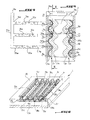
- the fuel cell cell of the invention comprises a routing conduit for fuel 10a disposed between the active layer 3a and the bipolar plate 5a and, similarly, a conduit 10c oxidant conveyance disposed between the layer active 3c and bipolar plate5c.
- routing conduits 10a, 10c are each in serpentine shape having an open end 11a, 11c which passes through cell 1 and through which the gas corresponding, fuel or oxidant, is introduced, a opposite end 13a, 13c which can be closed and perforations 12a, 12c made along the coil and crossed by the reactive gas which then spreads homogeneously in the corresponding active layer 3a, 3c and over its entire length of the cell.
- the routing ducts 10a, 10c are circular cross-section tubes and have a diameter of approximately 0.5 mm.
- the perforations 12a, 12c are circular and have a diameter of about 0.2 mm.
- the routing conduit 10a, 10c can be realized in an electrically conductive material such as stainless steel, for example, which ensures the electrical contact between the active layer 3a, 3c and the bipolar plate 5a, 5c when the active layer 3a, 3c is not in contact with this bipolar plate corresponding 5a, 5c according to the cell of the figure 2.
- this led 10a, 10c can be perforated by laser to form circular perforations 12a, 12c.
- These perforations 12a, 12c can be arranged regularly or not on the routing 10a, 10c.
- perforations 12a, 12c are regularly spaced from each other along the coil, they can be spaced about 2 mm apart.
- each routing conduit serpentine 10a, 10c may be located in the cell.
- a metal grid 14a, 14c is disposed between the bipolar plate 5a, 5c and the active layer 3a, 3c.
- This metal grid 14a, 14c presents in section perpendicular to the bipolar plates 5a, 5c, a corrugated shape forming cavities 15a, 15c between the bipolar plate 5a, 5c and the gate 14a, 14c defined by the distant waves of the bipolar plates 5a, 5c.
- the active layer 3a, 3c rests on the entire surface of the metal grid 14a and 14c and thus presents a ripple imposed by this grid 14a, 14c.
- the electrolyte 4 which is taken into sandwich between the two active layers 3a and 3c present also a ripple imposed by geometry corrugated metal grids 14a and 14c since it is preferable that the electrolyte is in contact with any the surface of the active layers 3a and 3c to ensure better the protonic transfer.
- the corrugation of the metal grid 14a, 14c is of sinusoidal type along the entire length of cell 1.
- the metal grid 14a, 14c can be constituted by any porous layer made of a material electrically conductive, both flexible enough to be collapsed but also strong enough to support the active layers 3a, 3c and the electrolyte 4.
- metal grids 14a and 14c can present folds or undulations of geometry different the sinusoidal geometry previously described of any geometry since the interest of the presence of such grids 14a, 14c is to increase the area of active layers 3a, 3c and thus also to increase the performance of the resulting stack.
- Cell 1 also includes a perforated conduit of fuel 10a which is introduced into each of the cavities 15a formed by the waves of the metal gate 14a opposite the bipolar plate 5a.
- a conduit Perforated delivery of the 10c oxidant is introduced in each of the cavities 15c formed by the waves of the 14c metal gate opposite the bipolar plate 5c.
- 10c are preferably circular cross section and can present a diameter of approximately 0.5 mm.
- the perforations 12a, 12c of each led 10a, 10c are circular and have a diameter of about 0.2 mm.
- these perforations 12a, 12c are preferably spaced apart from each other by about 2 mm.
- the metal grid 14a, 14c may have points of contact 141a, 141c with the bipolar plate corresponding 5a, 5c.
- each metal grid 14a, 14c has zones or points of contact 141a, 141c with the bipolar plate corresponding 5a, 5c which allows these plates 5a and 5c to perform their function of current collector.
- these contact points 141a, 141c are defined by the vertices of the waves directly in contact on bipolar plates 5a, 5c.
- the routing ducts 10a, 10c can be made of an insulating material since the electrical contact between the active layers 3a, 3c and the bipolar plates 5a, 5c is made by the points contact 141a, 141c.
- routing ducts 10a, 10c be made of an electrically conductive material and are in contact with both bipolar plates 5a, 5c and the metal grids 14a, 14c so as to allow the passage of the current of the active layers 3a, 3c to bipolar plates 5a, 5c.
- the electrically conductive material used to manufacture the routing ducts 10a, 10c is stainless steel.
- conduits of routing 10a, 10c are made of an electrically conductor
- these conduits 10a, 10c can be perforated by laser to form circular perforations 12a, 12c.
- each routing conduit 10a, 10c has a free end 13a, 13c which can be closed and an opposite end 16a, 16c which is connected to a transverse feed manifold 17a, 17c extending tranversally to the delivery ducts 10a, 10c when these extend in the same plan parallel to each other.
- every closed free end of a conduit 10a, 10c is located in cell 1.
- the common feed collectors 17a, 17c are preferably cross-sectional tubes circular.
- the collectors common fuel supply 17a and oxidizer 17c are preferably attached to the outside of the cell on an insulating and hermetic housing 20 which encapsulates the metal grids 14a, 14c, the active layers 3a, 3c and the electrolyte 4.
- routing ducts 10a, 10c pass through the insulating housing 20 being disposed in the cavities 15a, 15c.
- Common fuel collectors 17a and 17c each have an end 18a, 18c through which the gas enters and a opposite end closed 19a, 19c shown on the figure 6.
- the gas circulates in the common collector feeding 17a and then in the routing ducts 10a, which allows to supply fuel to each cavity in a homogeneous way 15a along its entire length.
- routing ducts 10a, 10c can provide, in addition of gas distribution, maintaining the grids respective metal parts 14a, 14c in their corrugated form when these grids 14a, 14c are made in one relatively flexible material.
- routing ducts 10a, 10c are arranged in cavities 15a, 15c without contact or with the metal grids 14a, 14c, or with the plates bipolar 5a, 5c. As explained previously, it is imperative, in this case, that the metal grids 14a, 14c are in contact with the bipolar plates 5a, 5c.
- the system constituted by the routing conduits 10a, 10c and their respective common supply manifold 17a, 17c can be used in the cell of the stack shown in Figure 2.
- the common feed collectors 17a, 17c can be arranged in the cell and are preferably made of an electrically conductor for the supply ducts 10a, 10c can ensure, where appropriate, the electrical contact between the active layers 3a, 3c and the plates bipolar 5a, 5c.
- conduit serpentine routing 10a, 10c of FIG. the cell shown in FIG. the configuration of the coil to the configuration geometric grids 14a, 14c.
- the routing conduit 10a, 10c may have any other configuration of that previously described in both embodiments, enabling it to ensure, on the one hand, the distribution homogeneous gas all along the active layer corresponding to 3a, 3c and, on the other hand, electrical contact between the active layer 3a, 3c and the bipolar plate 5a, 5c.
- conduits of fuel 10a and oxidant 10c can be part of the constitution of grids respective metal 14a, 14c.
- ducts 10a and 10c can pass alternatively through the meshes of the grids 14a, 14c or be welded to these grids 14a, 14c.
- these ducts 10a, 10c can forming all or part of the mesh of the grid 14a, 14c which eliminates the use of conduits 10a, 10c in addition to the grids 14a, 14c.
- the density of current is the same in every point in the layers 3a, 3c, which avoids the presence of a thermal gradient within the cell, as it is the case for the battery of the prior art shown in FIG. 1.
- routing conduits 10a, 10c in a fuel cell cell also allows to avoid the machining of the distribution channels 7a, 7c in bipolar plates 5a, 5c, which is very advantageous in terms of the manufacturing cost of bipolar plates that stack clutter resulting since the thickness of the bipolar plates 5a, 5c is no longer imposed by the presence of these channels 7a, 7c.
Landscapes
- Life Sciences & Earth Sciences (AREA)
- Engineering & Computer Science (AREA)
- Manufacturing & Machinery (AREA)
- Sustainable Development (AREA)
- Sustainable Energy (AREA)
- Chemical & Material Sciences (AREA)
- Chemical Kinetics & Catalysis (AREA)
- Electrochemistry (AREA)
- General Chemical & Material Sciences (AREA)
- Fuel Cell (AREA)
Applications Claiming Priority (2)
| Application Number | Priority Date | Filing Date | Title |
|---|---|---|---|
| FR0309070A FR2858116B1 (fr) | 2003-07-24 | 2003-07-24 | Cellule de pile comprenant un systeme de distribution des gaz reactifs |
| FR0309070 | 2003-07-24 |
Publications (1)
| Publication Number | Publication Date |
|---|---|
| EP1501143A1 true EP1501143A1 (de) | 2005-01-26 |
Family
ID=33484699
Family Applications (1)
| Application Number | Title | Priority Date | Filing Date |
|---|---|---|---|
| EP04291840A Withdrawn EP1501143A1 (de) | 2003-07-24 | 2004-07-19 | Ein Reaktivgasverteilungssystem umfassende Brennstoffzelle |
Country Status (2)
| Country | Link |
|---|---|
| EP (1) | EP1501143A1 (de) |
| FR (1) | FR2858116B1 (de) |
Cited By (1)
| Publication number | Priority date | Publication date | Assignee | Title |
|---|---|---|---|---|
| US8318380B2 (en) | 2007-02-05 | 2012-11-27 | Toyota Jidosha Kabushiki Kaisha | Fuel cell and vehicle having fuel cell |
Citations (6)
| Publication number | Priority date | Publication date | Assignee | Title |
|---|---|---|---|---|
| DE19853911A1 (de) * | 1998-11-23 | 2000-05-25 | Forschungszentrum Juelich Gmbh | Brennstoffzelle mit Zuführung eines Betriebsmittels über eine gelochte Platte |
| DE19905564A1 (de) * | 1999-02-11 | 2000-08-17 | Forschungszentrum Juelich Gmbh | Brennstoffzellenstapel mit Zuführung eines Betriebsmittels über eine gelochte Platte |
| EP1107339A2 (de) * | 1999-12-02 | 2001-06-13 | General Motors Corporation | Strömungskanäle in Stromabnehmerplatten von Brennstoffzellen |
| US6296964B1 (en) * | 1999-12-23 | 2001-10-02 | The Regents Of The University Of California | Enhanced methanol utilization in direct methanol fuel cell |
| EP1235289A2 (de) * | 2001-02-23 | 2002-08-28 | General Motors Corporation | Gestanzte bipolare Platte für PEM-Brennstoffzellenstapel |
| US20030039876A1 (en) * | 2001-08-27 | 2003-02-27 | Knights Shanna Denine | Electrochemical fuel cell with fluid distribution layer having non-uniform perforations |
-
2003
- 2003-07-24 FR FR0309070A patent/FR2858116B1/fr not_active Expired - Fee Related
-
2004
- 2004-07-19 EP EP04291840A patent/EP1501143A1/de not_active Withdrawn
Patent Citations (6)
| Publication number | Priority date | Publication date | Assignee | Title |
|---|---|---|---|---|
| DE19853911A1 (de) * | 1998-11-23 | 2000-05-25 | Forschungszentrum Juelich Gmbh | Brennstoffzelle mit Zuführung eines Betriebsmittels über eine gelochte Platte |
| DE19905564A1 (de) * | 1999-02-11 | 2000-08-17 | Forschungszentrum Juelich Gmbh | Brennstoffzellenstapel mit Zuführung eines Betriebsmittels über eine gelochte Platte |
| EP1107339A2 (de) * | 1999-12-02 | 2001-06-13 | General Motors Corporation | Strömungskanäle in Stromabnehmerplatten von Brennstoffzellen |
| US6296964B1 (en) * | 1999-12-23 | 2001-10-02 | The Regents Of The University Of California | Enhanced methanol utilization in direct methanol fuel cell |
| EP1235289A2 (de) * | 2001-02-23 | 2002-08-28 | General Motors Corporation | Gestanzte bipolare Platte für PEM-Brennstoffzellenstapel |
| US20030039876A1 (en) * | 2001-08-27 | 2003-02-27 | Knights Shanna Denine | Electrochemical fuel cell with fluid distribution layer having non-uniform perforations |
Cited By (1)
| Publication number | Priority date | Publication date | Assignee | Title |
|---|---|---|---|---|
| US8318380B2 (en) | 2007-02-05 | 2012-11-27 | Toyota Jidosha Kabushiki Kaisha | Fuel cell and vehicle having fuel cell |
Also Published As
| Publication number | Publication date |
|---|---|
| FR2858116A1 (fr) | 2005-01-28 |
| FR2858116B1 (fr) | 2005-11-11 |
Similar Documents
| Publication | Publication Date | Title |
|---|---|---|
| EP2007516B1 (de) | Wärmetauschersystem mit fluidzirkulationszonen, die selektiv mit einem katalysator für chemische reaktionen beschichtet sind | |
| EP1807895B1 (de) | Brennstoffzellenmodul mit flexiblen zwischenverbindern | |
| EP3776705A1 (de) | Bipolarplatte mit wellenförmigen kanälen | |
| FR2683094A1 (fr) | Batterie a oxyde metallique-hydrogene ayant des modules s'etendant longitudinalement par rapport a une receptacle sous pression. | |
| FR2819107A1 (fr) | Procede de fabrication d'un assemblage d'elements de base pour un etage de pile a combustible | |
| FR2858465A1 (fr) | Structures poreuses utilisables en tant que plaques bipolaires et procedes de preparation de telles structures poreuses | |
| FR2468220A1 (fr) | Electrode pour generateur electrochimique | |
| FR2819108A1 (fr) | Element de base composite et son joint pour pile a combustible et procede de fabrication de l'ensemble | |
| EP1749323B1 (de) | Festelektrolyt-brennstoffzelle | |
| EP1846976B1 (de) | Kompakter elektrochemischer wandler | |
| WO2012130932A1 (fr) | Pile a combustible a membrane d'echange de protons presentant une duree de vie accrue | |
| EP1501144B1 (de) | Brennstoffzelle mit hoher aktiver Oberfläche | |
| CA1051971A (fr) | Pile a combustible du type spirale | |
| EP1501143A1 (de) | Ein Reaktivgasverteilungssystem umfassende Brennstoffzelle | |
| WO2012130931A1 (fr) | Pile a combustible a membrane d'echange de protons presentant une duree de vie accrue | |
| EP3809504A1 (de) | Bipolare platte einer brennstoffzelle | |
| FR2858117A1 (fr) | Empilement de cellules dans une pile a combustible | |
| EP3092671B1 (de) | Flussleitende platte für eine brennstoffzelle | |
| FR2814857A1 (fr) | Micropiles a combustible notamment utilisees dans les dispositifs electroniques portables, dans les equipements automobiles et dans les dispositifs de telecommunication | |
| JP2010212084A (ja) | 燃料電池スタックおよびその製造方法 | |
| FR3141568A1 (fr) | Pile à combustible dotée d'un dispositif de compression | |
| KR20080040463A (ko) | 연료 개질기 | |
| FR2907968A1 (fr) | "plaque bipolaire de pile a combustible a circuit de fluide caloporteur ameliore, procede de fabrication et pile a combustible" | |
| FR2836283A1 (fr) | Pile a combustible a puissance renforcee et son procede de fabrication et utilisation pour la traction electrique d'un vehicule | |
| FR2997230A1 (fr) | Pile a combustible a membrane echangeuse de protons presentant une duree de vie et des performances accrues |
Legal Events
| Date | Code | Title | Description |
|---|---|---|---|
| PUAI | Public reference made under article 153(3) epc to a published international application that has entered the european phase |
Free format text: ORIGINAL CODE: 0009012 |
|
| AK | Designated contracting states |
Kind code of ref document: A1 Designated state(s): AT BE BG CH CY CZ DE DK EE ES FI FR GB GR HU IE IT LI LU MC NL PL PT RO SE SI SK TR |
|
| AX | Request for extension of the european patent |
Extension state: AL HR LT LV MK |
|
| 17P | Request for examination filed |
Effective date: 20050629 |
|
| AKX | Designation fees paid |
Designated state(s): AT BE BG CH CY CZ DE DK EE ES FI FR GB GR HU IE IT LI LU MC NL PL PT RO SE SI SK TR |
|
| 17Q | First examination report despatched |
Effective date: 20060821 |
|
| GRAP | Despatch of communication of intention to grant a patent |
Free format text: ORIGINAL CODE: EPIDOSNIGR1 |
|
| STAA | Information on the status of an ep patent application or granted ep patent |
Free format text: STATUS: THE APPLICATION IS DEEMED TO BE WITHDRAWN |
|
| 18D | Application deemed to be withdrawn |
Effective date: 20070926 |