EP1501678B1 - Machine de serigraphie - Google Patents
Machine de serigraphie Download PDFInfo
- Publication number
- EP1501678B1 EP1501678B1 EP02792661A EP02792661A EP1501678B1 EP 1501678 B1 EP1501678 B1 EP 1501678B1 EP 02792661 A EP02792661 A EP 02792661A EP 02792661 A EP02792661 A EP 02792661A EP 1501678 B1 EP1501678 B1 EP 1501678B1
- Authority
- EP
- European Patent Office
- Prior art keywords
- screen printing
- ring
- printing machine
- claw
- screen
- Prior art date
- Legal status (The legal status is an assumption and is not a legal conclusion. Google has not performed a legal analysis and makes no representation as to the accuracy of the status listed.)
- Expired - Lifetime
Links
- 238000012216 screening Methods 0.000 title 1
- 210000000078 claw Anatomy 0.000 claims abstract description 51
- 238000007650 screen-printing Methods 0.000 claims abstract description 31
- 230000005484 gravity Effects 0.000 claims description 3
- 230000002093 peripheral effect Effects 0.000 abstract 1
- 230000000712 assembly Effects 0.000 description 9
- 238000000429 assembly Methods 0.000 description 9
- 230000006835 compression Effects 0.000 description 5
- 238000007906 compression Methods 0.000 description 5
- 230000005540 biological transmission Effects 0.000 description 2
- 239000002775 capsule Substances 0.000 description 2
- 238000009434 installation Methods 0.000 description 2
- 230000007704 transition Effects 0.000 description 2
- 230000000295 complement effect Effects 0.000 description 1
- 238000010276 construction Methods 0.000 description 1
- 230000000694 effects Effects 0.000 description 1
- 239000004744 fabric Substances 0.000 description 1
- 238000004513 sizing Methods 0.000 description 1
Images




Classifications
-
- B—PERFORMING OPERATIONS; TRANSPORTING
- B41—PRINTING; LINING MACHINES; TYPEWRITERS; STAMPS
- B41F—PRINTING MACHINES OR PRESSES
- B41F15/00—Screen printers
- B41F15/08—Machines
- B41F15/0804—Machines for printing sheets
- B41F15/0809—Machines for printing sheets with cylindrical or belt-like screens
-
- B—PERFORMING OPERATIONS; TRANSPORTING
- B41—PRINTING; LINING MACHINES; TYPEWRITERS; STAMPS
- B41F—PRINTING MACHINES OR PRESSES
- B41F15/00—Screen printers
- B41F15/08—Machines
- B41F15/0831—Machines for printing webs
- B41F15/0836—Machines for printing webs by means of cylindrical screens or screens in the form of endless belts
-
- B—PERFORMING OPERATIONS; TRANSPORTING
- B41—PRINTING; LINING MACHINES; TYPEWRITERS; STAMPS
- B41F—PRINTING MACHINES OR PRESSES
- B41F15/00—Screen printers
- B41F15/14—Details
- B41F15/34—Screens, Frames; Holders therefor
- B41F15/38—Screens, Frames; Holders therefor curved
Definitions
- the invention relates to a screen printing machine according to the preamble of claim 1.
- the EP 1 090 752 A1 describes a screen cylinder for a screen printing machine.
- This screen cylinder is essentially composed of two support rings, which form the axial ends of the screen cylinder, and a screen in the form of a thin fabric jacket, whose edges are attached to the support rings.
- the support rings are rotatably mounted on frames of the screen printing machine.
- the screen cylinder must be removed and installed from time to time when changing jobs or to replace a worn screen.
- the support rings of the screen cylinder each have a sprocket or equivalent Kopptungs Rhein which is in engagement with a drive head of a transmission to drive the rotational movement of the screen cylinder. This intervention must be lifted each time removing the screen cylinder and restored when re-installing. This makes the installation and removal 'time consuming.
- the presence of the sprocket increases the weight of the support rings and makes handling difficult during installation and removal.
- the AT 382 821 B shows a round screen, which is fastened by means of bayonet lock in a storage.
- the DE 17 85 272 A1 discloses a mounting of a circular template, wherein for holding the round template on the receptacle rotatable claws are provided relative to each other.
- the AT 303 659 B By the AT 303 659 B , the AT 327 851 B and the DE 29 39 869 A1 are recordings for replaceable circular stencils known.
- the EP 0 863 000 A1 shows a storage for a round template, wherein the round template has conical surfaces.
- the invention has for its object to provide a screen printing machine.
- the support ring conventional screen cylinder is divided into two parts, on the one hand In a rotatably drivable ring, which is considered part of the bearing assembly of the screen cylinder, and must not be removed when replacing the screen cylinder, and on the other hand, a head of the screen cylinder, which on claws said ring is detachably mountable and only has the function to open the sieve In the desired cylindrical shape.
- the claws of each ring can be placed only on one half of its circumference.
- the rings of the two bearing assemblies each carry at least two jaws, at least one of which is in a position about the axis of the screen cylinder from a position in which it lies together with the at least one other jaw on one half of the circumference of the ring is rotatable, in which not all claws lie on one half of the circumference of the ring.
- the position in which the rotatable claw is fixed is preferably diametrically opposite with respect to the axis of the screen cylinder of the other claw. More generally, the center of gravity of the rotatable first jaw is diametrically opposed to the at least one other non-rotatable jaw.
- the ring has only a single jaw or claws, but which are immovable relative to each other.
- the claw or walls each have / has an intended for contact with the head inner surface / which lies on a centered about the axis of the screen cylinder cone, wherein the Vertex of the cone on that side of the claw bearing assembly is facing away from the other bearing assembly.
- spring elements may be provided which exert on a claw mounted on the head piece from the other bearing arrangement fort oriented axial force. These spring elements can serve different tasks.
- the screen printing machine can be designed such that, in its operation, the spring elements keep a gap between the head piece and the inner surfaces of the retaining claws open.
- the axial stress under which the screen is is determined in such a case by the force of the spring elements, and is adjustable by adjusting the axial position of the rings within certain limits.
- the inner surfaces of the jaws touch the flange during operation of the sizing press, for example in order to clamp and hold it.
- the spring elements can serve, during Removal of the screen cylinder whose head pieces to release again from the retaining claws. This may be necessary, in particular, if the ink residue sticks to the claws during the course of operation.
- a head piece for a screen cylinder has a cylindrical support portion for attaching a screen and a radially projecting flange connected to the support portion to which the jaws can engage.
- its flange In order to be able to transmit a rotational drive force from the ring to the head piece, its flange preferably has a non-circular radial cross-section, in particular in the form of two successive sections of different radial width in the circumferential direction.
- the extent of these sections in the circumferential direction is preferably dimensioned so that radially oriented surfaces which separate the sections of different radial width of the flange from each other, abut against a respective lateral edge of a claw.
- Fig.1 shows a partial perspective view of a screen printing machine according to the invention.
- a screen cylinder 01 held by target bearing assemblies 02; 03, which are each mounted on frames only partially shown 04 of the screen printing machine.
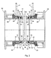
- Each bearing assembly 02; 03 and the screen cylinder 01 is particularly with reference to Fig. 2 explained.
- Each bearing assembly 02; 03 includes a fixedly connected to the respective frame 04, hollow cylindrical shaft 06, on which a ring 07 via a bearing 08, z. B. a needle bearing 08 is rotatably mounted.
- An outer ring gear 09 of each ring 07 is surrounded on a large part of its circumference by a fixedly connected to the adjacent frame 04 sleeve.
- An in Fig. 1 shown window 10 of the sleeve allows the engagement of a gear 11 in the ring gear 09 of the bearing assemblies 02, 03.
- the gears 11 on both sides of the screen printing machine can be driven by a drive motor at the same speeds via a not shown gear.
- the ring is composed of two concentric part rings 12, 14, an inner part ring 12 which carries the ring gear 09 and a later explained in more detail first jaw 13, and an outer part ring 14 which is rotatable about the inner part ring 12 around and a second Claw 16 is wearing.
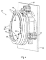
- the Fig. 2 as well as the perspective view of Fig. 4 these two claws 13; 16 shown diametrically opposite each other.
- the outer part ring 14 is rotationally fixed with respect to the inner part ring 12 by a spring capsule 17, which is embedded in the inner part ring 12 and a ball 18 in a recess on the inner part of the ring 12 facing inside of the outer part ring 14 suppressed.
- the two claws 13; 16 each have a parallel to the axis of the screen cylinder 01 extending stem portion 19; 21 and a from the free end of the stem portion 19 and 21 radially to the axis of the screen cylinder 01 extending towards the head portion 22 and 23rd
- the stem portion 19 of the first jaw 13 extends semicircular over half of the circumference of the ring 07.
- the head portion 22 of the first jaw 13 is in contrast shorter.
- the rotatable second jaw 16 in turn extends over approximately 30 ° of the circumference of the ring. She is from the in Fig. 4 rotated position shown in a position in which its head portion 23, the side 26 of the head portion 22 contacts, so that both jaws 13, 16 together extend over exactly half of the circumference of the ring 07.
- the screen cylinder 01 comprises, as in Fig. 1 to recognize two head pieces 27, each for mounting on the bearing assemblies 02; 03 are provided, and one of the head pieces 27 cylinder-shaped strained screen 28.
- this head piece 27 is integrally constructed of a cylindrical support portion 29, the outer surface is provided to it the screen 28 in a conventional manner fasten, and a radially projecting flange 31 which are interconnected by a transition portion 32 having a smaller outer diameter than that of the support portion 29 and the flange 31, respectively.
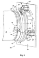
- Fig. 3 shows a partial perspective view of the screen cylinder 01 with a head piece 27.
- the flange 31 of the head piece 27 has two circumferentially offset from each other by radially oriented surfaces 33 sections 34; 36 with different radii.
- the radius of the smaller radius portion 34 corresponds to the inner radius of the stem portion 19, that of the larger radius portion 36 to the outer radius of the stem portion 19 or, which is preferably the same except for a small clearance
- the thus formed flange 31 is conveniently insertable in a movement transverse to the axis of the screen cylinder 01 into the bearing assembly 02 and 03, respectively , When inserting the radially oriented surfaces 33 come into contact with the sides of the stem portion 21.
- the bearing assembly 03 In order to tighten the wire 28 of the screen cylinder 01 mounted in this way on the bearing assemblies 02, 03, the bearing assembly 03 with three linear actuators 37 in the form of a working cylinder, for. B. a pneumatic or hydraulic cylinder equipped, which are able to move the ring 07 in the axial direction. These linear actuators 37 are actuated to move the ring 07 of the bearing assembly 03 in the direction of the opposite bearing assembly 02 and so the screen 28 to relax when the screen cylinder 01 is to be dismantled. After assembling a screen cylinder 01, the unear directors 37 pull the ring 07 in the opposite direction to tighten the screen 28.
- the flange 31 has two sections of different radius, which in the assembled state by the sides 24; 28 of the claw 42 contacting radial surfaces are connected to ensure an accurate transmission of the rotational movement of the ring 07 on the screen cylinder 01.
- the inner surface 43 of the pawl 42 comes into intimate contact with the flange 31.
- the conical shape of the inner surface 43 and the surface of the flange 31 facing it effect in that a radially outwardly directed force acts on the flange 31 along the inner surface 43, which prevents the flange 31 from escaping from the claw 42.
- z. B. compression springs 44 are provided to when the sieve 28 is relaxed for the disassembly of the screen cylinder 01, the contact between the inner surface 43 and the flange 31 to solve and so the removal of the head piece from the bearing assembly 02; 03 to facilitate.
- each ring or partial ring only one jaw 13; 16 or 42 carries.
- the number of claws can in principle be arbitrary, as long as all claws find place in an angular range of 180 °, so that they the lateral introduction of a head piece in the bearing assemblies 02; 03 does not hinder.
Landscapes
- Engineering & Computer Science (AREA)
- Mechanical Engineering (AREA)
- Screen Printers (AREA)
- Manufacturing Of Printed Wiring (AREA)
- Paper (AREA)
- Holo Graphy (AREA)
- Combined Means For Separation Of Solids (AREA)
Claims (10)
- Machine de sérigraphie avec deux agencements de palier (02 ; 03) destinés à recevoir un cylindre de sérigraphie (01), chaque agencement de palier (02 ; 03) présentant au moins une griffe (13 ; 16) fixant au moins une partie d'un cylindre de sérigraphie (01), les griffes (13 ; 16) étant fixées sur une bague rotative (07), caractérisée en ce qu'au moins un agencement de palier (02 ; 03) présente au moins deux griffes (13 ; 16) pouvant être tournées l'une par rapport à l'autre dans le sens périphérique, en ce que la bague (07) est constituée par deux bagues partielles (12 ; 14) concentriques, une bague partielle interne (12) étant prévue, qui porte une première griffe (13) et une bague partielle externe (14) étant prévue, qui peut tourner autour de la bague partielle interne (12) et qui porte une deuxième griffe (16).
- Machine de sérigraphie selon la revendication 1, caractérisée en ce qu'au moins un agencement de palier (03) présente un dispositif de commande linéaire (37) réalisé sous forme de vérin pour le déplacement de la bague (07) dans le sens axial.
- Machine de sérigraphie selon la revendication 1 ou 2, caractérisée en ce qu'au moins la première griffe (13) peut être tournée d'une position, dans laquelle elle est placée ensemble avec au moins une autre griffe (16) sur une moitié de la périphérie du cylindre de sérigraphie (01), autour de l'axe de rotation du cylindre de sérigraphie (01) dans une position dans laquelle toutes les griffes (13 ; 16) ne sont pas situées sur une moitié de la périphérie du cylindre de sérigraphie (01).
- Machine de sérigraphie selon la revendication 1 ou 2, caractérisée en ce que la première griffe (13) peut être tournée dans une position dans laquelle le centre de gravité de la première griffe (13) est diamétralement opposé à celui d'au moins une autre griffe (16) par rapport à l'axe de rotation du cylindre de sérigraphie (01).
- Machine de sérigraphie selon l'une quelconque des revendications précédentes, caractérisée en ce que les griffes (13 ; 16) de la bague (07) d'au moins un agencement de palier (02 ; 03) présentent des éléments à ressort (41 ; 44) pour exercer une force axiale orientée à l'encontre de l'autre agencement de palier (03 ; 02) sur une flasque (31) d'un cylindre de sérigraphie (01) pouvant être montée sur les griffes (13 ; 16).
- Machine de sérigraphie selon la revendication 5, caractérisée en ce que lors du fonctionnement de la machine de sérigraphie, les éléments à ressort (41) maintiennent ouverte une fente (38) entre la flasque (31) et les surfaces internes des griffes (13 ; 16).
- Machine de sérigraphie selon l'une quelconque des revendications précédentes, où le cylindre de sérigraphie (01) présente une section d'appui cylindrique (29) pour la fixation d'un écran (28) et une flasque (31) reliée à la section d'appui (29), en saillie dans le sens radial, caractérisée en ce que la flasque (31) part en saillie radialement vers l'extérieur à partir de la section d'appui (29).
- Machine de sérigraphie selon la revendication 7, caractérisée en ce que la section de la flasque (31) transversalement à l'axe n'est pas ronde.
- Machine de sérigraphie selon la revendication 7, caractérisée en ce que la flasque (31) présente, dans le sens de la périphérie, deux sections (34 ; 36) présentant une largeur radiale différente.
- Machine de sérigraphie selon la revendication 9, caractérisée en ce que les sections (34, 36) de largeur radiale différente sont séparées par des surfaces (33) orientées radialement et en ce que les surfaces orientées radialement (33) sont toutes deux disposées contre un bord latéral des griffes (13 ; 16).
Priority Applications (2)
| Application Number | Priority Date | Filing Date | Title |
|---|---|---|---|
| EP10189094.5A EP2311635B1 (fr) | 2002-05-03 | 2002-12-16 | Dispositif de palier d'un cylindre de sérigraphie |
| EP10189095A EP2311636B1 (fr) | 2002-05-03 | 2002-12-16 | Dispositif de palier d'un cylindre de sérigraphie |
Applications Claiming Priority (3)
| Application Number | Priority Date | Filing Date | Title |
|---|---|---|---|
| DE10219845 | 2002-05-03 | ||
| DE10219845A DE10219845C1 (de) | 2002-05-03 | 2002-05-03 | Siebdruckmaschine und Siebzylinder |
| PCT/DE2002/004580 WO2003093013A2 (fr) | 2002-05-03 | 2002-12-16 | Machine de serigraphie et cylindre de serigraphie |
Related Child Applications (4)
| Application Number | Title | Priority Date | Filing Date |
|---|---|---|---|
| EP10189095A Division EP2311636B1 (fr) | 2002-05-03 | 2002-12-16 | Dispositif de palier d'un cylindre de sérigraphie |
| EP10189094.5A Division EP2311635B1 (fr) | 2002-05-03 | 2002-12-16 | Dispositif de palier d'un cylindre de sérigraphie |
| EP10189094.5 Division-Into | 2010-10-27 | ||
| EP10189095.2 Division-Into | 2010-10-27 |
Publications (3)
| Publication Number | Publication Date |
|---|---|
| EP1501678A2 EP1501678A2 (fr) | 2005-02-02 |
| EP1501678B1 true EP1501678B1 (fr) | 2011-01-26 |
| EP1501678B9 EP1501678B9 (fr) | 2011-09-14 |
Family
ID=29265044
Family Applications (3)
| Application Number | Title | Priority Date | Filing Date |
|---|---|---|---|
| EP10189095A Expired - Lifetime EP2311636B1 (fr) | 2002-05-03 | 2002-12-16 | Dispositif de palier d'un cylindre de sérigraphie |
| EP02792661A Expired - Lifetime EP1501678B9 (fr) | 2002-05-03 | 2002-12-16 | Machine de serigraphie |
| EP10189094.5A Expired - Lifetime EP2311635B1 (fr) | 2002-05-03 | 2002-12-16 | Dispositif de palier d'un cylindre de sérigraphie |
Family Applications Before (1)
| Application Number | Title | Priority Date | Filing Date |
|---|---|---|---|
| EP10189095A Expired - Lifetime EP2311636B1 (fr) | 2002-05-03 | 2002-12-16 | Dispositif de palier d'un cylindre de sérigraphie |
Family Applications After (1)
| Application Number | Title | Priority Date | Filing Date |
|---|---|---|---|
| EP10189094.5A Expired - Lifetime EP2311635B1 (fr) | 2002-05-03 | 2002-12-16 | Dispositif de palier d'un cylindre de sérigraphie |
Country Status (8)
| Country | Link |
|---|---|
| US (2) | US7287467B2 (fr) |
| EP (3) | EP2311636B1 (fr) |
| JP (2) | JP4417830B2 (fr) |
| CN (2) | CN1318214C (fr) |
| AT (1) | ATE496769T1 (fr) |
| AU (1) | AU2002358436A1 (fr) |
| DE (2) | DE10219845C1 (fr) |
| WO (1) | WO2003093013A2 (fr) |
Families Citing this family (12)
| Publication number | Priority date | Publication date | Assignee | Title |
|---|---|---|---|---|
| EP1961559A1 (fr) * | 2007-02-20 | 2008-08-27 | Kba-Giori S.A. | Corps cylindrique d'orientation de paillettes magnétiques contenues dans une encre ou un vernis appliquées sur un substrat en forme de feuille ou de bande |
| EP1990208A1 (fr) | 2007-05-10 | 2008-11-12 | Kba-Giori S.A. | Dispositif et procédé pour transférer magnétiquement un indice vers une composition de revêtement appliquée à un substrat |
| EP2025515A1 (fr) * | 2007-08-16 | 2009-02-18 | Kba-Giori S.A. | Imprimante de sérigraphie |
| US20110174173A1 (en) * | 2010-01-18 | 2011-07-21 | Stork Prints America, Inc. | Split end ring for rotary printing screen and method |
| ES2540864T3 (es) | 2010-09-24 | 2015-07-14 | Kba-Notasys Sa | Sistema y método para orientar escamas o laminillas magnéticas contenidas en un vehículo de tinta o barniz aplicado sobre un sustrato en forma de lámina o en forma de banda |
| JP2015030251A (ja) * | 2013-08-06 | 2015-02-16 | 株式会社小森コーポレーション | ロータリースクリーン印刷装置 |
| CN103978777B (zh) * | 2014-05-08 | 2016-09-14 | 芦翠华 | 一种转轮印刷机的可调式版筒固定器 |
| DE102014226869B4 (de) | 2014-12-22 | 2022-03-17 | Koenig & Bauer Ag | Rakeleinrichtung für eine Siebdruckmaschine und Siebdruckmaschine |
| EP3448681B1 (fr) | 2016-04-25 | 2020-06-03 | J. Zimmer Maschinenbau Gesellschaft m.b.H. | Anneau de réception de pochoir rond et dispositif d'application rotatif équipé d'un tel anneau de réception de pochoir rond |
| DE102016007574A1 (de) * | 2016-06-21 | 2017-12-21 | Fresenius Medical Care Deutschland Gmbh | Zweikomponentige Abtropfkante |
| CN106274033A (zh) | 2016-10-12 | 2017-01-04 | 京东方科技集团股份有限公司 | 一种印刷机 |
| CN113524889A (zh) * | 2021-08-19 | 2021-10-22 | 李付军 | 旋转丝网滚筒装置 |
Family Cites Families (20)
| Publication number | Priority date | Publication date | Assignee | Title |
|---|---|---|---|---|
| DE178527C (fr) | 1905-11-12 | 1906-11-17 | ||
| AT303659B (de) * | 1968-05-22 | 1972-12-11 | Zimmer Johannes | Schablonenaufnahme für Rundschablonen |
| DE1761462A1 (de) * | 1967-05-26 | 1971-06-16 | Zimmer Johannes | Einrichtung an Schablonendruckmaschinen |
| AT296928B (de) | 1967-05-26 | 1972-03-10 | Johannes Zimmer | Schablonenaufnahme für Rundschablonen |
| CH463444A (de) * | 1967-09-26 | 1968-10-15 | Buser Ag Maschf Fritz | Rotationsfilmdruckmaschine |
| OA02976A (fr) * | 1967-09-26 | 1970-12-15 | Buser Ag Maschf Fritz | Machine rotative à imprimer sur film. |
| NL6910510A (fr) * | 1969-07-09 | 1971-01-12 | ||
| CH549474A (de) * | 1973-01-29 | 1974-05-31 | Buser Ag Maschf Fritz | Vorrichtung an rotationsfilmdruckmaschine zum loesbaren befestigen einer rundschablone. |
| CH550664A (de) * | 1973-02-27 | 1974-06-28 | Buser Ag Maschf Fritz | Rotationsfilmdruckmaschine. |
| US4026208A (en) * | 1973-11-21 | 1977-05-31 | Raylar Corporation | Rotary printing screen having heat-shrunk support members |
| DE2557247A1 (de) * | 1974-12-30 | 1976-07-01 | Johannes Zimmer | Schablonenaufnahme |
| DE2939869A1 (de) * | 1979-10-02 | 1981-04-23 | Saueressig Gmbh, 4422 Ahaus | Druckmaschine zum mehrfabrigen bedrucken einer durchlaufenden warenbahn |
| AT382821B (de) * | 1983-08-04 | 1987-04-10 | Zimmer Johannes | Rundschablonen-druckmaschine |
| DE3867993D1 (de) * | 1987-10-09 | 1992-03-05 | Stork Brabant Bv | Mehrfarbenrotationssiebdruckmaschine. |
| JPH03121848A (ja) * | 1989-10-04 | 1991-05-23 | Uenoyama Kiko Kk | ロータリスクリーン捺染機におけるスクリーンローラ支持装置 |
| US5301000A (en) * | 1989-12-13 | 1994-04-05 | Siemens Nixdorf Informationssysteme Aktiengesellschaft | Fixing station for an electrophotographic printing or copying apparatus |
| AT395694B (de) | 1991-09-17 | 1993-02-25 | Zimmer Maschinenbau Gmbh | Schablonenaufnahme fuer rundschablonen |
| JP2949575B2 (ja) * | 1997-02-10 | 1999-09-13 | 株式会社イチノセインターナショナル | ロータリスクリーン捺染機 |
| DE59914407D1 (de) * | 1999-10-08 | 2007-08-23 | Gallus Ferd Rueesch Ag | Lager für das Rundsieb bei Rotationssiebdruckwerken |
| DE10085449T1 (de) * | 2000-03-15 | 2003-01-30 | Fujitsu Ltd | Fixiervorrichtung |
-
2002
- 2002-05-03 DE DE10219845A patent/DE10219845C1/de not_active Expired - Fee Related
- 2002-12-16 DE DE50214889T patent/DE50214889D1/de not_active Expired - Lifetime
- 2002-12-16 CN CNB028288858A patent/CN1318214C/zh not_active Expired - Fee Related
- 2002-12-16 WO PCT/DE2002/004580 patent/WO2003093013A2/fr not_active Ceased
- 2002-12-16 JP JP2004501169A patent/JP4417830B2/ja not_active Expired - Fee Related
- 2002-12-16 AU AU2002358436A patent/AU2002358436A1/en not_active Abandoned
- 2002-12-16 EP EP10189095A patent/EP2311636B1/fr not_active Expired - Lifetime
- 2002-12-16 CN CN2007100052542A patent/CN101028754B/zh not_active Expired - Fee Related
- 2002-12-16 EP EP02792661A patent/EP1501678B9/fr not_active Expired - Lifetime
- 2002-12-16 EP EP10189094.5A patent/EP2311635B1/fr not_active Expired - Lifetime
- 2002-12-16 US US10/513,162 patent/US7287467B2/en not_active Expired - Lifetime
- 2002-12-16 AT AT02792661T patent/ATE496769T1/de active
-
2007
- 2007-06-20 US US11/820,717 patent/US7458319B2/en not_active Expired - Fee Related
-
2008
- 2008-12-19 JP JP2008324249A patent/JP4373483B2/ja not_active Expired - Fee Related
Also Published As
| Publication number | Publication date |
|---|---|
| US20050160925A1 (en) | 2005-07-28 |
| CN101028754B (zh) | 2010-05-19 |
| WO2003093013A2 (fr) | 2003-11-13 |
| EP1501678B9 (fr) | 2011-09-14 |
| US7287467B2 (en) | 2007-10-30 |
| US7458319B2 (en) | 2008-12-02 |
| JP2009061789A (ja) | 2009-03-26 |
| DE50214889D1 (de) | 2011-03-10 |
| US20070261575A1 (en) | 2007-11-15 |
| JP2005529000A (ja) | 2005-09-29 |
| ATE496769T1 (de) | 2011-02-15 |
| EP1501678A2 (fr) | 2005-02-02 |
| JP4373483B2 (ja) | 2009-11-25 |
| JP4417830B2 (ja) | 2010-02-17 |
| AU2002358436A1 (en) | 2003-11-17 |
| CN1625470A (zh) | 2005-06-08 |
| DE10219845C1 (de) | 2003-11-20 |
| EP2311636A1 (fr) | 2011-04-20 |
| WO2003093013B1 (fr) | 2004-04-22 |
| EP2311635B1 (fr) | 2015-02-25 |
| WO2003093013A3 (fr) | 2004-02-26 |
| EP2311635A1 (fr) | 2011-04-20 |
| CN101028754A (zh) | 2007-09-05 |
| EP2311636B1 (fr) | 2012-08-22 |
| CN1318214C (zh) | 2007-05-30 |
Similar Documents
| Publication | Publication Date | Title |
|---|---|---|
| EP0894623B1 (fr) | Groupe imprimant pour une machine rotative | |
| EP1501678B9 (fr) | Machine de serigraphie | |
| EP2835236B1 (fr) | Logement de couteau pour machine pour la découpe de viande | |
| DE102005018310B4 (de) | Spannfutter | |
| DE19751117A1 (de) | Vorrichtung zur Vermeidung von Spiel zwischen den kämmenden Zähnen eines ersten und eines zweiten Zahnrads in einem Druckwerk einer Offset-Rotationsdruckmaschine | |
| DE3938261C2 (fr) | ||
| EP0172412B1 (fr) | Cylindre de transfert de feuilles dans les rotatives d'impression de feuilles | |
| DE60010901T2 (de) | Segmentierte rolle | |
| DE102011104403B4 (de) | Verfahren zur Kalibration einer Reibungskupplung und Formwerkzeug dafür | |
| EP2371487B1 (fr) | Dispositif d'outil rotatif entraîné de manière rotative | |
| DE10245235B4 (de) | Spannsatz | |
| DE102010015432A1 (de) | Torsionsschwingsungsdämpfer | |
| DE10348310A1 (de) | Plattenzylinder mit einem Zylinderkörper und wenigstens einem Mantelelement | |
| EP1529578B1 (fr) | Machine de travail, en particulier machine de cintrage de fil et/ou de bande | |
| WO2000074869A1 (fr) | Systeme pour changer l'ecrou maintenant un cylindre de laminage | |
| EP2103828B1 (fr) | Couplage | |
| DE102004045098B4 (de) | Vorrichtung zur fernsteuerbaren Betätigung von Klemmelementen | |
| WO2005064771A1 (fr) | Dispositif de fixation d'un palier a roulement | |
| EP4516436A1 (fr) | Moyen de serrage interne | |
| DE102007016011B4 (de) | Vorrichtung zur Aufnahme einer Doppelkupplung in einer Auswuchtmaschine | |
| DE10330303B4 (de) | Falzzylinder zur Bearbeitung von Druckerzeugnissen | |
| EP4591697A1 (fr) | Organe de coupe d'une faucheuse | |
| DE102004033570B4 (de) | Werkzeug zum Lösen eines ersten Bauteils, wie eines Gelenkzapfens, aus einer kraftschlüssigen Verbindung mit einem zweiten Bauteil, wie einem Lenkhebel | |
| DE102024121551A1 (de) | Dämpfungseinheit mit Schnittstelle für einen Hebel zum manuellen Rotieren | |
| EP2469105A1 (fr) | Embout fileté et dispositif de verrouillage pour la fixation de deux composants |
Legal Events
| Date | Code | Title | Description |
|---|---|---|---|
| PUAI | Public reference made under article 153(3) epc to a published international application that has entered the european phase |
Free format text: ORIGINAL CODE: 0009012 |
|
| 17P | Request for examination filed |
Effective date: 20041111 |
|
| AK | Designated contracting states |
Kind code of ref document: A2 Designated state(s): AT BE BG CH CY CZ DE DK EE ES FI FR GB GR IE IT LI LU MC NL PT SE SI SK TR |
|
| AX | Request for extension of the european patent |
Extension state: AL LT LV MK RO |
|
| DAX | Request for extension of the european patent (deleted) | ||
| 17Q | First examination report despatched |
Effective date: 20081117 |
|
| RAP1 | Party data changed (applicant data changed or rights of an application transferred) |
Owner name: KBA-GIORI S.A. |
|
| GRAP | Despatch of communication of intention to grant a patent |
Free format text: ORIGINAL CODE: EPIDOSNIGR1 |
|
| RTI1 | Title (correction) |
Free format text: SCREENING MACHINE |
|
| GRAS | Grant fee paid |
Free format text: ORIGINAL CODE: EPIDOSNIGR3 |
|
| GRAA | (expected) grant |
Free format text: ORIGINAL CODE: 0009210 |
|
| AK | Designated contracting states |
Kind code of ref document: B1 Designated state(s): AT BE BG CH CY CZ DE DK EE ES FI FR GB GR IE IT LI LU MC NL PT SE SI SK TR |
|
| REG | Reference to a national code |
Ref country code: GB Ref legal event code: FG4D Free format text: NOT ENGLISH |
|
| REG | Reference to a national code |
Ref country code: CH Ref legal event code: PFA Owner name: KBA-NOTASYS SA Free format text: KBA-GIORI S.A.#AVENUE DU GREY 55 CASE POSTALE 347#1000 LAUSANNE 22 (CH) -TRANSFER TO- KBA-NOTASYS SA#AVENUE DU GREY 55 CASE POSTALE 347#1000 LAUSANNE 22 (CH) Ref country code: CH Ref legal event code: EP |
|
| RAP2 | Party data changed (patent owner data changed or rights of a patent transferred) |
Owner name: KBA-NOTASYS SA |
|
| REG | Reference to a national code |
Ref country code: IE Ref legal event code: FG4D Free format text: LANGUAGE OF EP DOCUMENT: GERMAN |
|
| REF | Corresponds to: |
Ref document number: 50214889 Country of ref document: DE Date of ref document: 20110310 Kind code of ref document: P |
|
| REG | Reference to a national code |
Ref country code: DE Ref legal event code: R096 Ref document number: 50214889 Country of ref document: DE Effective date: 20110310 |
|
| REG | Reference to a national code |
Ref country code: NL Ref legal event code: VDEP Effective date: 20110126 |
|
| PG25 | Lapsed in a contracting state [announced via postgrant information from national office to epo] |
Ref country code: ES Free format text: LAPSE BECAUSE OF FAILURE TO SUBMIT A TRANSLATION OF THE DESCRIPTION OR TO PAY THE FEE WITHIN THE PRESCRIBED TIME-LIMIT Effective date: 20110507 Ref country code: GR Free format text: LAPSE BECAUSE OF FAILURE TO SUBMIT A TRANSLATION OF THE DESCRIPTION OR TO PAY THE FEE WITHIN THE PRESCRIBED TIME-LIMIT Effective date: 20110427 Ref country code: PT Free format text: LAPSE BECAUSE OF FAILURE TO SUBMIT A TRANSLATION OF THE DESCRIPTION OR TO PAY THE FEE WITHIN THE PRESCRIBED TIME-LIMIT Effective date: 20110526 Ref country code: SE Free format text: LAPSE BECAUSE OF FAILURE TO SUBMIT A TRANSLATION OF THE DESCRIPTION OR TO PAY THE FEE WITHIN THE PRESCRIBED TIME-LIMIT Effective date: 20110126 |
|
| REG | Reference to a national code |
Ref country code: IE Ref legal event code: FD4D |
|
| PG25 | Lapsed in a contracting state [announced via postgrant information from national office to epo] |
Ref country code: SI Free format text: LAPSE BECAUSE OF FAILURE TO SUBMIT A TRANSLATION OF THE DESCRIPTION OR TO PAY THE FEE WITHIN THE PRESCRIBED TIME-LIMIT Effective date: 20110126 Ref country code: CY Free format text: LAPSE BECAUSE OF FAILURE TO SUBMIT A TRANSLATION OF THE DESCRIPTION OR TO PAY THE FEE WITHIN THE PRESCRIBED TIME-LIMIT Effective date: 20110126 Ref country code: BG Free format text: LAPSE BECAUSE OF FAILURE TO SUBMIT A TRANSLATION OF THE DESCRIPTION OR TO PAY THE FEE WITHIN THE PRESCRIBED TIME-LIMIT Effective date: 20110426 Ref country code: FI Free format text: LAPSE BECAUSE OF FAILURE TO SUBMIT A TRANSLATION OF THE DESCRIPTION OR TO PAY THE FEE WITHIN THE PRESCRIBED TIME-LIMIT Effective date: 20110126 Ref country code: NL Free format text: LAPSE BECAUSE OF FAILURE TO SUBMIT A TRANSLATION OF THE DESCRIPTION OR TO PAY THE FEE WITHIN THE PRESCRIBED TIME-LIMIT Effective date: 20110126 |
|
| PG25 | Lapsed in a contracting state [announced via postgrant information from national office to epo] |
Ref country code: EE Free format text: LAPSE BECAUSE OF FAILURE TO SUBMIT A TRANSLATION OF THE DESCRIPTION OR TO PAY THE FEE WITHIN THE PRESCRIBED TIME-LIMIT Effective date: 20110126 Ref country code: IE Free format text: LAPSE BECAUSE OF FAILURE TO SUBMIT A TRANSLATION OF THE DESCRIPTION OR TO PAY THE FEE WITHIN THE PRESCRIBED TIME-LIMIT Effective date: 20110126 Ref country code: DK Free format text: LAPSE BECAUSE OF FAILURE TO SUBMIT A TRANSLATION OF THE DESCRIPTION OR TO PAY THE FEE WITHIN THE PRESCRIBED TIME-LIMIT Effective date: 20110126 |
|
| PG25 | Lapsed in a contracting state [announced via postgrant information from national office to epo] |
Ref country code: SK Free format text: LAPSE BECAUSE OF FAILURE TO SUBMIT A TRANSLATION OF THE DESCRIPTION OR TO PAY THE FEE WITHIN THE PRESCRIBED TIME-LIMIT Effective date: 20110126 Ref country code: CZ Free format text: LAPSE BECAUSE OF FAILURE TO SUBMIT A TRANSLATION OF THE DESCRIPTION OR TO PAY THE FEE WITHIN THE PRESCRIBED TIME-LIMIT Effective date: 20110126 |
|
| PLBE | No opposition filed within time limit |
Free format text: ORIGINAL CODE: 0009261 |
|
| STAA | Information on the status of an ep patent application or granted ep patent |
Free format text: STATUS: NO OPPOSITION FILED WITHIN TIME LIMIT |
|
| 26N | No opposition filed |
Effective date: 20111027 |
|
| REG | Reference to a national code |
Ref country code: DE Ref legal event code: R097 Ref document number: 50214889 Country of ref document: DE Effective date: 20111027 |
|
| PG25 | Lapsed in a contracting state [announced via postgrant information from national office to epo] |
Ref country code: IT Free format text: LAPSE BECAUSE OF FAILURE TO SUBMIT A TRANSLATION OF THE DESCRIPTION OR TO PAY THE FEE WITHIN THE PRESCRIBED TIME-LIMIT Effective date: 20110126 |
|
| BERE | Be: lapsed |
Owner name: KBA-GIORI S.A. Effective date: 20111231 |
|
| PG25 | Lapsed in a contracting state [announced via postgrant information from national office to epo] |
Ref country code: MC Free format text: LAPSE BECAUSE OF NON-PAYMENT OF DUE FEES Effective date: 20111231 |
|
| PG25 | Lapsed in a contracting state [announced via postgrant information from national office to epo] |
Ref country code: BE Free format text: LAPSE BECAUSE OF NON-PAYMENT OF DUE FEES Effective date: 20111231 |
|
| REG | Reference to a national code |
Ref country code: AT Ref legal event code: MM01 Ref document number: 496769 Country of ref document: AT Kind code of ref document: T Effective date: 20111216 |
|
| PG25 | Lapsed in a contracting state [announced via postgrant information from national office to epo] |
Ref country code: LU Free format text: LAPSE BECAUSE OF NON-PAYMENT OF DUE FEES Effective date: 20111216 |
|
| PG25 | Lapsed in a contracting state [announced via postgrant information from national office to epo] |
Ref country code: AT Free format text: LAPSE BECAUSE OF NON-PAYMENT OF DUE FEES Effective date: 20111216 |
|
| PG25 | Lapsed in a contracting state [announced via postgrant information from national office to epo] |
Ref country code: TR Free format text: LAPSE BECAUSE OF FAILURE TO SUBMIT A TRANSLATION OF THE DESCRIPTION OR TO PAY THE FEE WITHIN THE PRESCRIBED TIME-LIMIT Effective date: 20110126 |
|
| REG | Reference to a national code |
Ref country code: FR Ref legal event code: PLFP Year of fee payment: 14 |
|
| REG | Reference to a national code |
Ref country code: FR Ref legal event code: PLFP Year of fee payment: 15 |
|
| REG | Reference to a national code |
Ref country code: FR Ref legal event code: PLFP Year of fee payment: 16 |
|
| PGFP | Annual fee paid to national office [announced via postgrant information from national office to epo] |
Ref country code: FR Payment date: 20191220 Year of fee payment: 18 |
|
| PGFP | Annual fee paid to national office [announced via postgrant information from national office to epo] |
Ref country code: CH Payment date: 20191220 Year of fee payment: 18 |
|
| PGFP | Annual fee paid to national office [announced via postgrant information from national office to epo] |
Ref country code: GB Payment date: 20191220 Year of fee payment: 18 |
|
| REG | Reference to a national code |
Ref country code: CH Ref legal event code: PL |
|
| GBPC | Gb: european patent ceased through non-payment of renewal fee |
Effective date: 20201216 |
|
| PG25 | Lapsed in a contracting state [announced via postgrant information from national office to epo] |
Ref country code: FR Free format text: LAPSE BECAUSE OF NON-PAYMENT OF DUE FEES Effective date: 20201231 |
|
| PG25 | Lapsed in a contracting state [announced via postgrant information from national office to epo] |
Ref country code: LI Free format text: LAPSE BECAUSE OF NON-PAYMENT OF DUE FEES Effective date: 20201231 Ref country code: CH Free format text: LAPSE BECAUSE OF NON-PAYMENT OF DUE FEES Effective date: 20201231 Ref country code: GB Free format text: LAPSE BECAUSE OF NON-PAYMENT OF DUE FEES Effective date: 20201216 |
|
| PGFP | Annual fee paid to national office [announced via postgrant information from national office to epo] |
Ref country code: DE Payment date: 20211102 Year of fee payment: 20 |
|
| REG | Reference to a national code |
Ref country code: DE Ref legal event code: R071 Ref document number: 50214889 Country of ref document: DE |