EP1990208A1 - Dispositif et procédé pour transférer magnétiquement un indice vers une composition de revêtement appliquée à un substrat - Google Patents
Dispositif et procédé pour transférer magnétiquement un indice vers une composition de revêtement appliquée à un substrat Download PDFInfo
- Publication number
- EP1990208A1 EP1990208A1 EP07107966A EP07107966A EP1990208A1 EP 1990208 A1 EP1990208 A1 EP 1990208A1 EP 07107966 A EP07107966 A EP 07107966A EP 07107966 A EP07107966 A EP 07107966A EP 1990208 A1 EP1990208 A1 EP 1990208A1
- Authority
- EP
- European Patent Office
- Prior art keywords
- coating composition
- magnetic
- layer
- magnetic permeability
- magnetic field
- Prior art date
- Legal status (The legal status is an assumption and is not a legal conclusion. Google has not performed a legal analysis and makes no representation as to the accuracy of the status listed.)
- Withdrawn
Links
- 239000008199 coating composition Substances 0.000 title claims abstract description 68
- 238000000034 method Methods 0.000 title claims abstract description 28
- 239000000758 substrate Substances 0.000 title claims abstract description 25
- 230000005291 magnetic effect Effects 0.000 claims abstract description 163
- 239000000463 material Substances 0.000 claims abstract description 48
- 230000035699 permeability Effects 0.000 claims abstract description 47
- 239000002245 particle Substances 0.000 claims abstract description 26
- 239000002966 varnish Substances 0.000 claims abstract description 14
- 238000007639 printing Methods 0.000 claims description 31
- PXHVJJICTQNCMI-UHFFFAOYSA-N Nickel Chemical compound [Ni] PXHVJJICTQNCMI-UHFFFAOYSA-N 0.000 claims description 14
- 238000007650 screen-printing Methods 0.000 claims description 12
- RYGMFSIKBFXOCR-UHFFFAOYSA-N Copper Chemical compound [Cu] RYGMFSIKBFXOCR-UHFFFAOYSA-N 0.000 claims description 8
- 229910052802 copper Inorganic materials 0.000 claims description 8
- 239000010949 copper Substances 0.000 claims description 8
- 229910052759 nickel Inorganic materials 0.000 claims description 7
- XEEYBQQBJWHFJM-UHFFFAOYSA-N Iron Chemical compound [Fe] XEEYBQQBJWHFJM-UHFFFAOYSA-N 0.000 claims description 6
- 229910045601 alloy Inorganic materials 0.000 claims description 6
- 239000000956 alloy Substances 0.000 claims description 6
- 239000003302 ferromagnetic material Substances 0.000 claims description 6
- 238000001035 drying Methods 0.000 claims description 5
- 239000004411 aluminium Substances 0.000 claims description 4
- 229910052782 aluminium Inorganic materials 0.000 claims description 4
- XAGFODPZIPBFFR-UHFFFAOYSA-N aluminium Chemical compound [Al] XAGFODPZIPBFFR-UHFFFAOYSA-N 0.000 claims description 4
- 238000007646 gravure printing Methods 0.000 claims description 4
- 229910017052 cobalt Inorganic materials 0.000 claims description 3
- 239000010941 cobalt Substances 0.000 claims description 3
- GUTLYIVDDKVIGB-UHFFFAOYSA-N cobalt atom Chemical compound [Co] GUTLYIVDDKVIGB-UHFFFAOYSA-N 0.000 claims description 3
- 229910052742 iron Inorganic materials 0.000 claims description 3
- 238000012546 transfer Methods 0.000 claims description 3
- 230000001939 inductive effect Effects 0.000 claims description 2
- 239000000976 ink Substances 0.000 description 14
- 230000008569 process Effects 0.000 description 10
- 239000000049 pigment Substances 0.000 description 9
- 230000000694 effects Effects 0.000 description 7
- 238000004088 simulation Methods 0.000 description 6
- 230000001747 exhibiting effect Effects 0.000 description 5
- 230000003287 optical effect Effects 0.000 description 5
- 238000012360 testing method Methods 0.000 description 5
- 238000001723 curing Methods 0.000 description 4
- 230000002238 attenuated effect Effects 0.000 description 2
- 230000008901 benefit Effects 0.000 description 2
- 230000008859 change Effects 0.000 description 2
- 239000003795 chemical substances by application Substances 0.000 description 2
- 238000013461 design Methods 0.000 description 2
- 230000004907 flux Effects 0.000 description 2
- 230000006872 improvement Effects 0.000 description 2
- 230000004048 modification Effects 0.000 description 2
- 238000012986 modification Methods 0.000 description 2
- 229910000938 samarium–cobalt magnet Inorganic materials 0.000 description 2
- 239000007787 solid Substances 0.000 description 2
- 229910000570 Cupronickel Inorganic materials 0.000 description 1
- 229910002482 Cu–Ni Inorganic materials 0.000 description 1
- 241001596784 Pegasus Species 0.000 description 1
- 229910000831 Steel Inorganic materials 0.000 description 1
- 238000003848 UV Light-Curing Methods 0.000 description 1
- 239000003082 abrasive agent Substances 0.000 description 1
- 238000013459 approach Methods 0.000 description 1
- 238000003486 chemical etching Methods 0.000 description 1
- KPLQYGBQNPPQGA-UHFFFAOYSA-N cobalt samarium Chemical compound [Co].[Sm] KPLQYGBQNPPQGA-UHFFFAOYSA-N 0.000 description 1
- 239000012141 concentrate Substances 0.000 description 1
- YOCUPQPZWBBYIX-UHFFFAOYSA-N copper nickel Chemical class [Ni].[Cu] YOCUPQPZWBBYIX-UHFFFAOYSA-N 0.000 description 1
- 238000005520 cutting process Methods 0.000 description 1
- 230000003247 decreasing effect Effects 0.000 description 1
- 238000006073 displacement reaction Methods 0.000 description 1
- 238000009826 distribution Methods 0.000 description 1
- 230000005684 electric field Effects 0.000 description 1
- 230000005672 electromagnetic field Effects 0.000 description 1
- 238000004049 embossing Methods 0.000 description 1
- 239000011521 glass Substances 0.000 description 1
- 238000007603 infrared drying Methods 0.000 description 1
- 238000000608 laser ablation Methods 0.000 description 1
- 239000007788 liquid Substances 0.000 description 1
- 239000000696 magnetic material Substances 0.000 description 1
- 238000004519 manufacturing process Methods 0.000 description 1
- 239000011159 matrix material Substances 0.000 description 1
- 239000000203 mixture Substances 0.000 description 1
- 229910000889 permalloy Inorganic materials 0.000 description 1
- 239000004033 plastic Substances 0.000 description 1
- 238000007493 shaping process Methods 0.000 description 1
- 239000010959 steel Substances 0.000 description 1
- XLYOFNOQVPJJNP-UHFFFAOYSA-N water Substances O XLYOFNOQVPJJNP-UHFFFAOYSA-N 0.000 description 1
Images


Classifications
-
- B—PERFORMING OPERATIONS; TRANSPORTING
- B41—PRINTING; LINING MACHINES; TYPEWRITERS; STAMPS
- B41M—PRINTING, DUPLICATING, MARKING, OR COPYING PROCESSES; COLOUR PRINTING
- B41M7/00—After-treatment of prints, e.g. heating, irradiating, setting of the ink, protection of the printed stock
- B41M7/0045—After-treatment of prints, e.g. heating, irradiating, setting of the ink, protection of the printed stock using protective coatings or film forming compositions cured by mechanical wave energy, e.g. ultrasonics, cured by electromagnetic radiation or waves, e.g. ultraviolet radiation, electron beams, or cured by magnetic or electric fields, e.g. electric discharge, plasma
-
- B—PERFORMING OPERATIONS; TRANSPORTING
- B41—PRINTING; LINING MACHINES; TYPEWRITERS; STAMPS
- B41M—PRINTING, DUPLICATING, MARKING, OR COPYING PROCESSES; COLOUR PRINTING
- B41M3/00—Printing processes to produce particular kinds of printed work, e.g. patterns
- B41M3/14—Security printing
-
- B—PERFORMING OPERATIONS; TRANSPORTING
- B41—PRINTING; LINING MACHINES; TYPEWRITERS; STAMPS
- B41M—PRINTING, DUPLICATING, MARKING, OR COPYING PROCESSES; COLOUR PRINTING
- B41M7/00—After-treatment of prints, e.g. heating, irradiating, setting of the ink, protection of the printed stock
- B41M7/0036—After-treatment of prints, e.g. heating, irradiating, setting of the ink, protection of the printed stock using protective coatings or layers dried without curing
-
- B—PERFORMING OPERATIONS; TRANSPORTING
- B42—BOOKBINDING; ALBUMS; FILES; SPECIAL PRINTED MATTER
- B42D—BOOKS; BOOK COVERS; LOOSE LEAVES; PRINTED MATTER CHARACTERISED BY IDENTIFICATION OR SECURITY FEATURES; PRINTED MATTER OF SPECIAL FORMAT OR STYLE NOT OTHERWISE PROVIDED FOR; DEVICES FOR USE THEREWITH AND NOT OTHERWISE PROVIDED FOR; MOVABLE-STRIP WRITING OR READING APPARATUS
- B42D25/00—Information-bearing cards or sheet-like structures characterised by identification or security features; Manufacture thereof
- B42D25/20—Information-bearing cards or sheet-like structures characterised by identification or security features; Manufacture thereof characterised by a particular use or purpose
- B42D25/29—Securities; Bank notes
-
- B—PERFORMING OPERATIONS; TRANSPORTING
- B42—BOOKBINDING; ALBUMS; FILES; SPECIAL PRINTED MATTER
- B42D—BOOKS; BOOK COVERS; LOOSE LEAVES; PRINTED MATTER CHARACTERISED BY IDENTIFICATION OR SECURITY FEATURES; PRINTED MATTER OF SPECIAL FORMAT OR STYLE NOT OTHERWISE PROVIDED FOR; DEVICES FOR USE THEREWITH AND NOT OTHERWISE PROVIDED FOR; MOVABLE-STRIP WRITING OR READING APPARATUS
- B42D25/00—Information-bearing cards or sheet-like structures characterised by identification or security features; Manufacture thereof
- B42D25/30—Identification or security features, e.g. for preventing forgery
- B42D25/36—Identification or security features, e.g. for preventing forgery comprising special materials
- B42D25/369—Magnetised or magnetisable materials
-
- B42D2033/16—
Definitions
- the present invention generally relates to a device and method for magnetically transferring indicia to a coating composition, such as an ink or varnish, applied to at least a part of the surface of a substrate, which coating composition comprises magnetic or magnetizable particles.
- a coating composition such as an ink or varnish
- the present invention also relates to the use of such a device and the application of such a method to produce printed documents, such as banknotes or like valuable and security documents.
- a layer of coating composition such as an ink or varnish, is first applied to at least a part of the surface of a substrate, which coating composition comprises at least one type of magnetic or magnetizable particles. While the layer of coating composition is still wet, the layer is exposed to a determined magnetic field generated at a surface of a magnetic-field-generating device, thereby orienting the magnetic or magnetizable particles along field lines of the magnetic field. The layer of coating composition is then dried or cured, thereby fixing the orientation of the magnetic or magnetizable particles.
- Magnetic or magnetizable particles also designated as “magnetic flakes"
- magnetic flakes Magnetic or magnetizable particles
- European patent application EP 0 686 675 European patent application EP 0 686 675
- International applications WO 02/073250 WO 03/000801 , WO 2004/007095 , WO 2004/007096 and WO 2005/002866 .
- Such particles or flakes are in particular used as optically-variable pigments in so-called optically-variable inks, or OVI®'s (OVI® is a registered trademark of SICPA Holding SA, Switzerland) to produce high-level security patterns, especially for banknotes.
- the most convenient method to apply the above magnetic flakes is by silk-screen printing as discussed in the above-mentioned International application WO 2005/000585 .
- This is mainly due to the fact that the flakes have a relatively important size which restricts the choice of available printing processes for applying inks or varnishes containing such flakes.
- silk-screen printing constitutes the most convenient printing process to achieve this goal.
- silk-screen printing has the advantage that the inks or varnishes used in such a process exhibit a relatively low viscosity which favours proper orientation of the magnetic flakes.
- Orientation of the magnetic flakes contained in the wet coating composition is carried out by applying an adequate magnetic field to the freshly-applied layer of coating composition.
- an adequate magnetic field By appropriately shaping the field lines of the magnetic field, the magnetic flakes can be aligned in any desired pattern producing a corresponding optically-variable effect which is very difficult, if not impossible to counterfeit.
- An adequate solution for orienting the magnetic flakes as discussed in International application WO 2005/000585 consists in bringing sheets carrying layers of wet coating composition in contact with a rotating cylinder carrying a plurality of magnetic-field-generating devices.
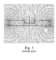
- Figure 1 is a schematic cross-sectional view of a magnetic field simulation taken from the above-mentioned International application which illustrates an example of a vertically magnetized permanent magnetic plate, designated by numerical reference 1, comprising a rectangular engraving 2.
- the engraved plate 1 is made of Plastoferrite (such as the Plastoferrite model M100.8 sold by Maurer Magnetic AG, CH-8627 Groningen, http://www.maurermagnetic.ch) magnetized in a direction perpendicular to the surface of the plate 1.
- Plastoferrite such as the Plastoferrite model M100.8 sold by Maurer Magnetic AG, CH-8627 Groningen, http://www.maurermagnetic.ch
- the field lines of the magnetic field are mostly vertical in the region of the surface of the body, except in the region of the vertical walls of the engraving 2. This implies that most of the magnetic pigments contained in the wet composition are aligned in a vertical manner, perpendicularly to the surface of the substrate. In other words, considering the fact that the pigments are mostly reflective when they are aligned substantially horizontally, the resulting pattern induced in the coating composition by means of the device of Figure 1 is mostly not reflective, when seen and illuminated perpendicularly to the surface of the substrate.
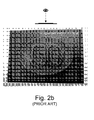
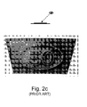
- Figures 2a to 2c are greyscale photographs, taken along three different viewing angles, of a magnetically-induced pattern representing the value "50" within an oval shape which was produced by means of a device according to the principle of International application WO 2005/002866 illustrated in Figure 1 . More precisely, the pattern was produced using a body having engravings representing the value "50" within an engraved oval shape.
- the layer of coating composition was applied with a silk-screen printing process on top of a black offset background using an OVI® silk-screen ink comprising gold-to-green optically variable magnetic pigment corresponding to the 7-layer pigment design disclosed in WO 02/73250 .
- the purpose of the black (or dark) offset background is to increase the contrast in the induced pattern by making the reflective parts of the pattern (i.e. the portions where the pigments are oriented substantially horizontally with respect to the surface of the substrate) stand out as compared to the less reflective parts of the pattern (i.e. the portions where the pigments are oriented substantially vertically with respect to the surface of the substrate, thereby revealing the underlying background).
- An aim of the invention is therefore to improve the known devices and methods for magnetically transferring indicia to a coating composition comprising magnetic or magnetizable particles
- a further aim of the present invention is to provide a device for magnetically transferring indicia to a coating composition comprising magnetic or magnetizable particles that is relatively easy and cheap to produce.
- Still another aim of the present invention is to provide a solution that increases the level of security of the resulting magnetically-induced pattern and makes it even more difficult to counterfeit.
- a device for magnetically transferring indicia to a layer of coating composition such as an ink or varnish, applied to at least a part of the surface of a substrate, the coating composition comprising at least one type of magnetic or magnetizable particles.
- the device comprises a body subjected to a magnetic field, which body carries determined indicia in the form of engravings on a surface of the body, which engravings influence the orientation of field lines of the magnetic field.
- the body further comprises at least one layer of material of high magnetic permeability in which the engravings are formed. In the absence of these engravings on the body, the field lines of the magnetic field extend substantially parallel to the surface of the body.
- the body further comprises a base plate of material of low magnetic permeability supporting the layer of material of high magnetic permeability.
- the layer of material of high magnetic permeability can advantageously be deposited on the base plate by galvanization.
- a preferred material for the base plate is a non-ferromagnetic material such as copper, aluminium or alloys thereof.
- the effect can be maximized when the engravings in the layer of material of high magnetic permeability extend through the whole thickness of the layer.
- the magnetic permeability of the layer of material of high magnetic permeability is selected to be greater than 100 ⁇ N/A 2 (@ 0.002 T), preferably between 100 to 1000 ⁇ N/A 2 (@ 0.002 T).
- a suitable material is a ferromagnetic material such as iron, nickel, cobalt or alloys thereof.
- the thickness of the layer of material of high magnetic permeability is preferably selected so as to be greater or equal to 50 microns, even more preferably between 50 to 500 microns.
- the magnetic field can advantageously be generated through electromagnetic means such as at least one permanent magnet or electromagnet, preferably two.
- electromagnetic means such as at least one permanent magnet or electromagnet, preferably two.
- other equivalent means susceptible of generating an electromagnetic field may also be used.
- the field lines of the magnetic field can extend along substantially one main direction parallel to the surface of the body.
- the device of the present invention can advantageously be shaped as a curved plate adapted for mounting onto a rotatable cylinder body of a printing press or as an individual curved plate element adapted for mounting onto a supporting member disposed on the circumference of a cylindrical body of a printing press.
- Also claimed is a method for magnetically transferring indicia onto a substrate, comprising the steps of :
- the coating composition is preferably applied by printing, even more preferably by silk-screen printing, flexographic printing or gravure printing.
- a printed document in particular a banknote, comprising a substrate with a coating composition applied to a least a part of a surface of the substrate and indicia magnetically-induced in the coating composition according to the above method.
- Yet another claimed object is the use of the above device for magnetically inducing transfer of indicia to a wet coating composition, such an ink or varnish, applied to at least a part of the surface of a substrate, which coating composition comprises at least one type of magnetic or magnetizable particles.
- Figure 3 is a schematic cross-sectional view of a magnetic-field-generating device, designated globally by reference numeral 10, according to a preferred embodiment of the present invention.
- the device 10 includes a body 20 the purpose of which is to influence the orientation of field lines of a magnetic field, as this will be explained hereinafter.
- the body 20 comprises a layer 21 made of material of high magnetic permeability in which engravings 21 a, 21 b, 21 c are formed, and a base plate 22 made of material of low magnetic permeability which supports the layer 21.
- FIG. 3 Also illustrated in Figure 3 is a sheet S disposed on top of the surface of the body 20 in contact with the upper surface of layer 21, which sheet S comprises a layer of coating composition P applied on the surface of the sheet S, opposite the surface of layer 21.
- Coating composition P comprises at least one type of magnetic or magnetizable particles, as discussed hereinabove, that one wishes to orient by means of the magnetic-field-generating device 10.
- the method for magnetically transferring indicia onto the substrate S comprises the steps of :
- a material of "high magnetic permeability” is a material that has the ability to concentrate the field lines of a magnetic field (i.e. is “magnetically attractable")
- a material of "low magnetic permeability” is a material that does not substantially affect the field lines of a magnetic field and behaves substantially like free space or vacuum.
- a material of "high magnetic permeability” is a material having a magnetic permeability p that is substantially greater than ⁇ 0 . More precisely, according to the present invention, material of high magnetic permeability will be understood as materials preferably exhibiting a magnetic permeability greater than 100 ⁇ N/A 2 (@ 0.002 T), even more preferably materials exhibiting a magnetic permeability between 100 to 1000 ⁇ N/A 2 (@ 0.002 T). It shall be understood that the magnetic permeability of materials varies with flux density. The above-mentioned values are therefore given considering a flux density of 0.002 T (hence the indication "@ 0.002 T" following the mentioned values).
- ferromagnetic materials such as iron, nickel, cobalt or alloys thereof (e.g. steel, permalloy, etc.).
- any material of high magnetic permeability is suitable. Tests have however shown that material exhibiting a magnetic permeability comprised between 100 to 1000 ⁇ N/A 2 (@ 0.002 T) are sufficient, and that materials exhibiting a magnetic permeability higher than 1000 ⁇ N/A 2 (@ 0.002 T), while also suitable, are not necessary.
- a particularly suitable material for layer 21 is nickel, which material has a magnetic permeability of approximately 125 ⁇ N/A 2 (@ 0.002 T).
- This material is convenient as it is commonly used in the banknote industry to produce intaglio printing plates, especially by galvanization, and is thus readily available to the banknote printer.
- This material is furthermore very easy to engrave (for instance mechanically by means of a rotating chisel or by means of gaseous or liquid jets of abrasives, by chemical etching, or even by laser ablation using CO 2 , Nd-YAG or excimer lasers).
- non-ferromagnetic materials such as copper, aluminium or alloys thereof.
- any material of low magnetic permeability is suitable. Glass or plastic could for instance be used as material for the base plate 22.
- the base plate 22 of material of low magnetic permeability is therefore not essential but preferred.
- a particularly suitable material for base plate 22 is copper, which material has a magnetic permeability of approximately 1.2566290 ⁇ N/A 2 . This material is also convenient as it is again commonly used in the banknote industry and is thus readily available to the banknote printer.
- a perfectly suitable alternative is aluminium which exhibits a magnetic permeability of approximately 1.2566650 ⁇ N/A 2 .
- the copper base plate 22 was approximately 0.5 mm thick and the nickel layer 21 was deposited by galvanization with layer thicknesses ranging from 50 to 500 microns.
- the magnetic field is generated in this example by a pair of permanent magnets 31, 32 (such as samarium-cobalt - SmCo - magnets as supplied by Maurer Magnetic AG) disposed at two ends I, II of the device 10.
- the permanent magnet 31 is disposed with its north magnetic pole oriented upwards
- the permanent magnet 32 is disposed with its north magnetic pole oriented downwards.
- the resulting magnetic field is such that field lines of the magnetic field will extend from the north magnetic pole of permanent magnet 31 at end I through the base plate 22, into layer 21, then substantially horizontally through, above and below the layer 21, from end I to end II, back through the base plate 22 and to the south magnetic pole of permanent magnet 32.
- the remainder of the magnetic circuit is closed through connection of the magnetic field lines at the lower part of the device, via the north magnetic pole of permanent magnet 32 and the south magnetic pole of permanent magnet 31. It will be appreciated that the same magnetic field configuration could alternatively be generated using electromagnets instead of the permanent magnets 31, 32.
- FIG. 4 A simulation of the resulting magnetic field distribution is shown schematically in Figure 4 .
- This simulation was produced using the publicly available modelling software Vizimag ( http://mvw.vonmag.com/ ) and considering a nickel layer as layer 21 and a copper base plate as base plate 22.
- the magnetic field lines would mostly be concentrated in the layer 21 itself, this layer 21 acting as a magnetic short-circuit.
- the engravings 21 a, 21 b, 21 c in the layer 21, which form in essence regions of low magnetic permeability (i.e. free space), force the magnetic field lines along different routes and orientations. In other words, the engravings 21a, 21b, 21c influence the orientation of the field lines of the magnetic field in the vicinity of the engravings 21 a, 21 b, 21 c.
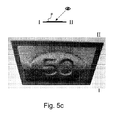
- Figures 5a to 5d are greyscale photographs taken from four different viewing angles of a magnetically induced pattern representing the value "50" within an oval shape, similar to the prior pattern illustrated in Figures 2a to 2c , but which was produced by means of a device according to the above-discussed preferred embodiment of the present invention.
- the body of the magnetic-field-generating device was engraved with exactly the same engraving pattern representing value "50" within an oval shape as that used for producing the prior pattern of Figures 2a to 2c .
- the above mentioned copper-nickel (Cu-Ni) body 20 was used.
- the resulting pattern is substantially more reflective and exhibits a radically different optical effect as compared to that illustrated in Figures 2a to 2c .
- the optical effect created according to the invention is more or less inverted as compared to the optical effect illustrated in Figures 2a to 2c .
- the oval shape appears to stand out in relief above the background, like a solid volume, with the value "50" looking like having been engraved into the solid oval shape.
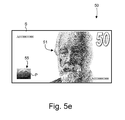
- Figure 5e is a schematic illustration of a possible banknote 50 comprising inter alia a portrait 51 and a magnetically-induced pattern 55 produced according to the present invention, such as the pattern of Figures 5a to 5d .
- the magnetic field lines are generally oriented along one main direction parallel to the surface of the body 20, that is along the direction I-II in Figures 3 and 4 .
- engraved lines in layer 21 oriented substantially parallel to this main direction I-II have a tendency to disappear or be attenuated in the resulting magnetically-induced pattern.
- Figures 5a to 5d one can in particular see that the side portions on the left-hand side and right-hand side of the oval shape are substantially attenuated.
- the engraved pattern so as to be devoid of engraved patterns extending along the main direction of the magnetic field lines and/or make the engraved pattern is such regions wide enough so as to cause a greater influence on the local orientation of the magnetic field lines.
- a solution might consist in changing the main direction of the magnetic field lines during exposure of the layer of coating composition P. This is preferably carried out by rotating, advantageously by 360°, the magnetic field with respect to the exposed layer of coating composition P.
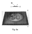
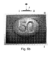
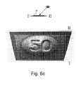
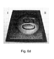
- Figures 6a to 6d are greyscale photographs taken along the same four different viewing angles as in Figures 5a to 5d of a magnetically-induced pattern representing the value "50" within an oval shape, identical to that of Figures 5a to 5d , with the additional provision that, during exposure of the layer of coating composition P, the main direction of the magnetic field lines was rotated by 360°.
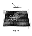
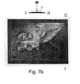
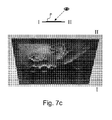
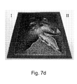
- Figures 7a to 7d are four photographs taken along the same four different viewing angles as those of Figures 5a to 5d and 6a to 6d , of another example of a magnetically-induced pattern.
- the main direction of the magnetic field was also rotated by 360° during exposure of the coating composition P.
- Figure 7e is a schematic top view of the engraved body 20 which was used in the context of the example shown in Figures 7a to 7d .
- the layer 21 of the body 20 was engraved with a pattern of engravings 211, 212 representing, on the one hand, a stylised representation of a Pegasus 211 and, on the other hand, the words "KBA GIORI" 212.
- the rectilinear or curvilinear patterns 211, 212 where engraved with a line width of approximately 1 millimeter. Tests have shown that a line width of 1 millimeter or more is preferable in the context of the present invention.
- too dense an engraving pattern is preferably to be avoided, i.e. a line spacing of 1 millimeter or more between neighbouring engravings is to be preferred.
- the thickness of layer 21 should be selected to be greater or equal to 50 microns, even more preferably in the range of 50 to 500 microns.
- the thickness of the base plate 22 on the other hand is not critical.
- the tests have shown that the distance between the permanent magnets 31, 32 and the body 20 had some influence on the resulting magnetically-induced pattern.
- the permanent magnets or, alternatively, the electromagnets
- the magnetic force of the magnets also plays a role.
- Electromagnets could be used in lieu of permanent magnets to create the necessary magnetic field. Electromagnets are particularly advantageous in that the magnetic field can be completely suppressed at the end of the exposure, thereby preventing further modification of the orientation of the magnetic or magnetizable particles, especially during removal of the substrate from the surface of the body 20.
- rotation of the main direction of the magnetic field can easily be carried out using electromagnets disposed in a circular arrangement and by electronically switching the orientation of the magnetic field in a manner similar to that performed in the context of the actuation of electric motors. Rotation of the magnetic field using permanent magnets would have to be performed by physical rotation of the permanent magnets themselves (or of the substrate S carrying the layer of coating composition P) during exposure.
- the above-described invention can be implemented by designing the above-described magnetic-field-generating device 10 so as to be disposed on the circumference of a cylindrical body of a printing press as generally taught in International application No. WO 2005/000585 in the name of the present Applicant.
- FIG 8 schematically illustrates one possible embodiment of a sheet-fed printing press as disclosed in International application No. WO 2005/000585 , which application is incorporated herein by reference.
- This printing press is adapted to print sheets according to the silk-screen printing process and comprises a feeding station 100 for feeding successive sheets to a silk-screen printing group 200 where silk-screen patterns are applied onto the sheets.
- the printing group 200 comprises an impression cylinder 200a cooperating with two screen cylinders 200b, 200c placed in succession along the printing path of the sheets.
- the freshly printed sheets are transported by means of a conveyor system 300 to a delivery station 400 comprising a plurality of delivery pile units, three in this example.
- the conveyor system 300 is typically an endless chain conveyor system comprising a plurality of spaced-apart gripper bars (not shown in Figure 8 ) extending transversely to the sheet transporting direction, each gripper bar comprising clamping means for holding a leading edge of the sheets.
- a cylinder body 600 carrying a plurality of magnetic-field-generating devices is located along the path of the sheets carried by the chain conveyor system 300.
- This cylinder body 600 is designed to apply a magnetic field to selected locations of the sheets for the purpose of orienting magnetic flakes contained in the patterns of coating composition which have been freshly-applied on the sheets in the printing group 200, as discussed above.
- a drying or curing unit 500 is provided downstream of the cylinder body 600 for drying, respectively curing, the coating composition applied onto the sheets after the magnetic flakes have been oriented and prior to the delivery in the delivery station 400, such unit 500 being typically an infrared drying unit or a UV curing unit depending on the type of coating composition used (e.g. water-based or UV-cured inks/varnishes).
- the cylinder body 600 could alternatively be located at the sheet transfer location 300a between the impression cylinder 200a and the conveyor system 300. Still according to another embodiment envisaged in International application No. WO 2005/000585 , the impression cylinder 200a itself could be designed as a cylinder carrying magnetic-field-generating devices.
- the cylinder body 600 used to orient the magnetic flakes advantageously cooperates with the non-freshly-printed side of the sheets, thereby preventing smearing problems, the magnetic field being applied from the back side of the sheets through the freshly-printed patterns of coating composition.
- the cylinder body 600 is rotated at a circumferential speed corresponding to the speed of the transported sheets so that there is no relative displacement between the transported sheets and the circumference of the cylinder.
- the cylinder body 600 is placed in the path of the chain conveyor system 300 such that the sheets follow a curved path tangential to the outer circumference of the cylinder body 600, thereby enabling part of the surface of the processed sheet to be brought in contact with the outer circumference of the cylinder body 600.
- each printed sheet (or each successive portion of a continuous web, in case of web-printing) carries an array of imprints arranged in a matrix of rows and columns, which imprints ultimately form individual securities after final cutting of the sheets or web portions.
- the cylinder body 600 used to orient the magnetic flakes is therefore typically provided with as many magnetic-field-generating devices as there are imprints on the sheets or web portions.
- the cylinder body 600 is preferably a cylinder body as further taught in European patent application No. 07102749.4 entitled "CYLINDER BODY FOR ORIENTING MAGNETIC FLAKES CONTAINED IN AN INK OR VARNISH VEHICLE PRINTED ON A SHEET-LIKE OR WEB-LIKE SUBSTRATE", filed on February 20, 2007 in the name of the present Applicant.
- the cylinder body advantageously comprises a plurality of distinct annular supporting rings distributed axially along a common shaft member, each annular supporting ring carrying a set of magnetic-field-generating devices which are distributed circumferentially on an outer circumference of the annular supporting rings. Thanks to this cylinder body configuration, the position of each magnetic-field-generating device can be adjusted to the corresponding position of the coating composition imprints on the processed sheets or web.
- the body 20 can be shaped as a curved plate adapted for mounting onto a rotatable cylinder body of a printing press (in such a case, a common plate with engravings could be used for all magnetic-field-generating devices) or, alternatively, as an individual curved plate element adapted for mounting onto a supporting member disposed on the circumference of a cylindrical body of a printing press (in such a case, individual plates would be used).
- the layer of coating composition P is preferably to be printed on a dark background
- any other background is possible such as for example a structured background as discussed in International application WO 2006/061301 .
- a mainly dark background is however preferred in order to yield a better contrast in the resulting magnetically-induced pattern.
Landscapes
- Physics & Mathematics (AREA)
- Engineering & Computer Science (AREA)
- Electromagnetism (AREA)
- Mechanical Engineering (AREA)
- Plasma & Fusion (AREA)
- Business, Economics & Management (AREA)
- Accounting & Taxation (AREA)
- Finance (AREA)
- Printing Methods (AREA)
- Credit Cards Or The Like (AREA)
Priority Applications (7)
| Application Number | Priority Date | Filing Date | Title |
|---|---|---|---|
| EP07107966A EP1990208A1 (fr) | 2007-05-10 | 2007-05-10 | Dispositif et procédé pour transférer magnétiquement un indice vers une composition de revêtement appliquée à un substrat |
| US12/599,353 US8893614B2 (en) | 2007-05-10 | 2008-05-07 | Device and method for magnetically transferring indicia to a coating composition applied to a substrate |
| PCT/IB2008/051784 WO2008139373A1 (fr) | 2007-05-10 | 2008-05-07 | Dispositif et procédé pour le transfert magnétique de marques à une composition de revêtement appliquée sur un substrat |
| EP08738092.9A EP2155498B1 (fr) | 2007-05-10 | 2008-05-07 | Dispositif et procédé pour transférer magnétiquement un indice vers une composition de revêtement appliquée à un substrat |
| CN2008800236318A CN101743127B (zh) | 2007-05-10 | 2008-05-07 | 用于将标记磁性地转移到被施用到基片的涂层成分的装置和方法 |
| ES08738092.9T ES2472740T3 (es) | 2007-05-10 | 2008-05-07 | Dispositivo y método para transferir magn�ticamente marcas de seguridad a una composición de recubrimiento aplicada a un substrato |
| JP2010507043A JP5547627B2 (ja) | 2007-05-10 | 2008-05-07 | 基材に塗布されたコーティング組成物に模様を磁気的に転写するための装置及び方法 |
Applications Claiming Priority (1)
| Application Number | Priority Date | Filing Date | Title |
|---|---|---|---|
| EP07107966A EP1990208A1 (fr) | 2007-05-10 | 2007-05-10 | Dispositif et procédé pour transférer magnétiquement un indice vers une composition de revêtement appliquée à un substrat |
Publications (1)
| Publication Number | Publication Date |
|---|---|
| EP1990208A1 true EP1990208A1 (fr) | 2008-11-12 |
Family
ID=38515858
Family Applications (2)
| Application Number | Title | Priority Date | Filing Date |
|---|---|---|---|
| EP07107966A Withdrawn EP1990208A1 (fr) | 2007-05-10 | 2007-05-10 | Dispositif et procédé pour transférer magnétiquement un indice vers une composition de revêtement appliquée à un substrat |
| EP08738092.9A Active EP2155498B1 (fr) | 2007-05-10 | 2008-05-07 | Dispositif et procédé pour transférer magnétiquement un indice vers une composition de revêtement appliquée à un substrat |
Family Applications After (1)
| Application Number | Title | Priority Date | Filing Date |
|---|---|---|---|
| EP08738092.9A Active EP2155498B1 (fr) | 2007-05-10 | 2008-05-07 | Dispositif et procédé pour transférer magnétiquement un indice vers une composition de revêtement appliquée à un substrat |
Country Status (6)
| Country | Link |
|---|---|
| US (1) | US8893614B2 (fr) |
| EP (2) | EP1990208A1 (fr) |
| JP (1) | JP5547627B2 (fr) |
| CN (1) | CN101743127B (fr) |
| ES (1) | ES2472740T3 (fr) |
| WO (1) | WO2008139373A1 (fr) |
Cited By (8)
| Publication number | Priority date | Publication date | Assignee | Title |
|---|---|---|---|---|
| EP2314386A1 (fr) * | 2009-10-22 | 2011-04-27 | manroland AG | Dispositif et procédé de revêtement |
| WO2011092502A3 (fr) * | 2010-02-01 | 2011-10-06 | De La Rue International Limited | Eléments de sécurité et procédés et appareil de fabrication associés |
| EP2548658A1 (fr) * | 2011-07-21 | 2013-01-23 | Pago Etikettiersysteme GmbH | Procédé d'impression magnétique et dispositif destiné à l'exécution de celui-ci |
| DE102014205638A1 (de) | 2013-03-27 | 2014-10-02 | Jds Uniphase Corp. | Optische Vorrichtung mit einem illusorischen optischen Effekt und Verfahren zur Herstellung |
| CN107471818A (zh) * | 2017-08-07 | 2017-12-15 | 甄欣 | 一种光磁双场形成可变安全图案的系统 |
| WO2018019594A1 (fr) * | 2016-07-29 | 2018-02-01 | Sicpa Holding Sa | Procédés de production de couches à effet |
| WO2018033512A1 (fr) * | 2016-08-16 | 2018-02-22 | Sicpa Holding Sa | Procédés de production de couches à effets |
| WO2025149523A1 (fr) * | 2024-01-09 | 2025-07-17 | Sun Chemical B.V. | Procédé d'impression à effet 3d |
Families Citing this family (42)
| Publication number | Priority date | Publication date | Assignee | Title |
|---|---|---|---|---|
| EP2845732B1 (fr) | 2010-09-24 | 2017-03-22 | KBA-NotaSys SA | Presse à imprimer sur feuilles et procédé pour orienter des flocons magnétiques contenus dans un véhicule d'encre ou de vernis appliqués sur un substrat de type feuille |
| CN102442097A (zh) * | 2010-09-30 | 2012-05-09 | 王玉珠 | 一种磁力印刷方法及其印刷产品 |
| PL2468423T3 (pl) * | 2010-12-27 | 2016-11-30 | System i sposób tworzenia obrazu na podłożu | |
| CN103129195B (zh) * | 2011-11-28 | 2016-05-25 | 珠海格力电器股份有限公司 | 磁性油墨印刷方法 |
| IN2014MN01369A (fr) * | 2012-01-12 | 2015-05-29 | Jds Uniphase Corp | |
| FR2986181B1 (fr) * | 2012-01-27 | 2014-02-21 | Oreal | Procede de realisation d'un decor sur un materiau support permettant la realisation d'etuis pour l'emballage d'un produit cosmetique |
| CN103386805B (zh) * | 2012-05-09 | 2015-01-21 | 中国人民银行印制科学技术研究所 | 磁定向滚筒 |
| AR094362A1 (es) * | 2013-01-09 | 2015-07-29 | Sicpa Holding Sa | Capas de efectos ópticos que muestran un efecto óptico que depende del ángulo de visión; procesos y dispositivos para la producción de esas capas, artículos que llevan una capa de efectos ópticos y usos de esas capas |
| HUE061637T2 (hu) | 2013-01-09 | 2023-08-28 | Sicpa Holding Sa | Látószögfüggõ optikai hatást mutató optikai hatású rétegek; eljárások és eszközök azok elõállítására; optikai hatású réteget hordozó tárgyak; és azok felhasználása |
| CN103303019A (zh) * | 2013-06-26 | 2013-09-18 | 常熟印刷厂有限公司 | 一种磁性出版物印刷方法 |
| CN104442055B (zh) * | 2014-11-27 | 2017-07-21 | 惠州市华阳光学技术有限公司 | 一种磁定向图案的制备方法及其制备设备 |
| CN106864014B (zh) * | 2015-12-10 | 2020-02-28 | 惠州市华阳光学技术有限公司 | 一种磁体和磁定向装置 |
| DE102015121822A1 (de) * | 2015-12-15 | 2017-06-22 | Bogen Electronic Gmbh | Gegenstand mit Informationen sowie Verfahren zum Aufbringen und Auslesen der Informationen des Gegenstands |
| AR107681A1 (es) | 2016-02-29 | 2018-05-23 | Sicpa Holding Sa | Aparatos y procesos para producir capas con efecto óptico que comprenden partículas de pigmento no esféricas orientadas magnéticas, o magnetizables |
| EP4600707A3 (fr) | 2016-08-31 | 2025-11-19 | Viavi Solutions Inc. | Article avec segments réfléchissants inclinés |
| US10357991B2 (en) | 2016-12-19 | 2019-07-23 | Viavi Solutions Inc. | Security ink based security feature |
| DE102017202747B3 (de) | 2017-02-21 | 2018-08-16 | Koenig & Bauer Ag | Verfahren zur Bearbeitung von Bedruckstoffbogen bei der Herstellung von Wertpapieren sowie Wertpapierdruckmaschine |
| CN106965579A (zh) * | 2017-03-20 | 2017-07-21 | 佛山市高明绿色德化工有限公司 | 一种渐变效果的玻璃印刷工艺 |
| FR3067729B1 (fr) * | 2017-06-19 | 2020-05-08 | Gerflor | Procede de realisation d'une couche decor presentant un aspect tridimensionnel |
| TWI794359B (zh) | 2018-01-17 | 2023-03-01 | 瑞士商西克帕控股有限公司 | 用於生產光學效應層之製程 |
| EP3790666B1 (fr) | 2018-05-08 | 2023-06-28 | Sicpa Holding Sa | Ensembles magnétiques, appareils et procédés de production de couches à effet optique comprenant des particules pigmentaires magnétiques ou magnétisables orientées non sphériques |
| DE102018004433A1 (de) * | 2018-06-05 | 2019-12-05 | Giesecke+Devrient Currency Technology Gmbh | Verfahren zum Herstellen eines Wertdokuments, Wertdokument und Druckvorrichtung |
| PL3829784T3 (pl) | 2018-07-30 | 2026-03-16 | Sicpa Holding Sa | Sposoby wytwarzania warstw efektów optycznych |
| PL3829891T3 (pl) * | 2018-07-30 | 2025-02-03 | Sicpa Holding Sa | Zespoły i sposoby do wytwarzania warstw z efektem optycznym zawierających zorientowane magnetyczne lub magnesowalne cząstki pigmentu |
| ES2988654T3 (es) | 2019-02-08 | 2024-11-21 | Sicpa Holding Sa | Conjuntos magnéticos y procesos para producir capas de efecto óptico que comprenden partículas de pigmento magnéticas o magnetizables, oblongas, no esféricas y orientadas |
| JP7387961B2 (ja) | 2019-03-28 | 2023-11-29 | シクパ ホルディング ソシエテ アノニム | 配向非球状磁性又は磁化可能顔料粒子を含む光学効果層を生成するための磁気アセンブリ及びプロセス |
| JP7633242B2 (ja) | 2019-10-28 | 2025-02-19 | シクパ ホルディング ソシエテ アノニム | 配向非球状磁性又は磁化可能顔料粒子を含む光学効果層を生成するための磁気アセンブリ及びプロセス |
| AU2020377282B2 (en) | 2019-10-28 | 2025-09-04 | Sicpa Holding Sa | Magnetic assemblies and processes for producing optical effect layers comprising oriented non-spherical magnetic or magnetizable pigment particles |
| CN110949029A (zh) * | 2019-12-04 | 2020-04-03 | 云南侨通包装印刷有限公司 | 一种分层式磁性光彩漫射效果的制作方法 |
| AU2021295043A1 (en) | 2020-06-23 | 2023-02-16 | Sicpa Holding Sa | Methods for producing optical effect layers comprising magnetic or magnetizable pigment particles |
| CN111942060A (zh) * | 2020-08-25 | 2020-11-17 | 彭亮 | 一种浮雕光变防伪元件 |
| TWI909026B (zh) | 2021-03-31 | 2025-12-21 | 瑞士商西克帕控股有限公司 | 包含磁性或可磁化顏料粒子且展現一或更多個標記的光學效應層及其產生方法 |
| CA3244906A1 (fr) | 2022-02-28 | 2023-08-31 | Sicpa Holding Sa | Procédés de production de couches à effet optique comprenant des particules de pigment magnétiques ou magnétisables et présentant un ou plusieurs indices |
| CN114633574A (zh) * | 2022-03-24 | 2022-06-17 | 彭亮 | 一种动态视觉立体效果的安全线或条 |
| CN119677597A (zh) | 2022-08-05 | 2025-03-21 | 锡克拜控股有限公司 | 包含磁性或可磁化颜料颗粒并展现一个以上的标记的光学效应层的生产方法 |
| CN115782385B (zh) * | 2022-12-05 | 2025-10-21 | 惠州市华阳光学技术有限公司 | 一种磁定向装置及印刷设备 |
| EP4688290A1 (fr) | 2023-04-03 | 2026-02-11 | Sicpa Holding SA | Appareils et procédés de production de couches à effets optiques |
| WO2024218531A1 (fr) * | 2023-04-20 | 2024-10-24 | Htc Technology Consulting | Alignement magnétique de pigments orientables magnétiquement dans une encre à champs magnétiques superposés. |
| CN116393336B (zh) * | 2023-06-09 | 2023-08-18 | 太原科技大学 | 用于磁致伸缩材料薄膜基体旋转涂布的夹具及其使用方法 |
| WO2025242568A1 (fr) | 2024-05-22 | 2025-11-27 | Sicpa Holding Sa | Appareils et procédés de production de couches à effet optique |
| WO2025242569A1 (fr) | 2024-05-22 | 2025-11-27 | Sicpa Holding Sa | Appareils et procédés de production de couches à effets optiques |
| DE102024127365A1 (de) | 2024-09-23 | 2026-03-26 | Giesecke+Devrient Currency Technology Gmbh | Verfahren zur Herstellung eines Wertdokuments und Wertdokument |
Citations (10)
| Publication number | Priority date | Publication date | Assignee | Title |
|---|---|---|---|---|
| US4838648A (en) | 1988-05-03 | 1989-06-13 | Optical Coating Laboratory, Inc. | Thin film structure having magnetic and color shifting properties |
| EP0686675A1 (fr) | 1994-06-01 | 1995-12-13 | BASF Aktiengesellschaft | Pigments métalliques brillants magnétisables à revêtements multiples |
| WO2002073250A2 (fr) | 2001-03-09 | 2002-09-19 | Sicpa Holding S.A. | Pigment ou dispositif d'interference en film mince magnetique et son procede de fabrication, encre d'impression ou composition de revetement, document de securite et utilisation d'un tel dispositif |
| WO2004007096A2 (fr) | 2002-07-15 | 2004-01-22 | Jds Uniphase Corporation | Planarisation magnetique de flocons de pigment |
| WO2004007095A2 (fr) | 2002-07-15 | 2004-01-22 | Jds Uniphase Corporation | Procede et appareil d'orientation des paillettes magnetiques |
| EP1493590A1 (fr) * | 2003-07-03 | 2005-01-05 | Sicpa Holding S.A. | Procédé et moyens de production d'un dessin induit par magnétisme dans une composition de revêtement contenant des particules magnétiques |
| WO2005000585A1 (fr) | 2003-06-30 | 2005-01-06 | Kba-Giori S.A. | Machine d'impression |
| EP1650042A1 (fr) | 2004-10-20 | 2006-04-26 | JDS Uniphase Corporation | Procédé d'alignement de particules magnétiques dans une encre pâteuse, et impression d'effets optiques |
| WO2006114289A1 (fr) * | 2005-04-27 | 2006-11-02 | Leonhard Kurz Gmbh & Co. Kg | Procede pour produire des elements createurs d'effet de couleurs |
| EP1787728A1 (fr) * | 2005-11-18 | 2007-05-23 | JDS Uniphase Corporation | Plaque magnétique pour imprimer des effets optiques |
Family Cites Families (26)
| Publication number | Priority date | Publication date | Assignee | Title |
|---|---|---|---|---|
| US4186944A (en) * | 1974-04-17 | 1980-02-05 | Emi Limited | Security document |
| JPS5656898A (en) * | 1979-10-15 | 1981-05-19 | Takeyoshi Yamaguchi | Printing method using magnetic force |
| JPS6168285A (ja) * | 1984-09-12 | 1986-04-08 | Fuji Photo Film Co Ltd | 印刷方法 |
| US5192611A (en) * | 1989-03-03 | 1993-03-09 | Kansai Paint Co., Ltd. | Patterned film forming laminated sheet |
| AU696709B2 (en) | 1995-01-24 | 1998-09-17 | Kba-Notasys Sa | Rotary screen printing machine for sheet printing |
| RU2157764C2 (ru) | 1995-10-20 | 2000-10-20 | Де ля Рю Жиори С.А. | Машина листовой печати |
| KR100438111B1 (ko) | 1996-02-19 | 2004-07-16 | 드라루지오리에쓰.에이. | 매엽지(枚葉紙)인쇄기용압동(壓胴) |
| CN1273293C (zh) | 1996-03-21 | 2006-09-06 | 吉奥里大街公司 | 丝网印刷机 |
| US6152035A (en) * | 1999-12-17 | 2000-11-28 | Universal Engraving, Inc. | Magnetic support plate for cladded steel and steel-backed polymer stamping/blocking and embossing graphic arts dies |
| US20020160194A1 (en) | 2001-04-27 | 2002-10-31 | Flex Products, Inc. | Multi-layered magnetic pigments and foils |
| EP1347879A1 (fr) * | 2001-12-14 | 2003-10-01 | Meccanica Masi | Dispositif d'impression pour machines a imprimer de divers types |
| DE10219845C1 (de) | 2002-05-03 | 2003-11-20 | Koenig & Bauer Ag | Siebdruckmaschine und Siebzylinder |
| EP1369230A1 (fr) * | 2002-06-05 | 2003-12-10 | Kba-Giori S.A. | Procédé de fabrication d'une plaque gravée |
| US7934451B2 (en) * | 2002-07-15 | 2011-05-03 | Jds Uniphase Corporation | Apparatus for orienting magnetic flakes |
| DE50304555D1 (de) * | 2002-10-17 | 2006-09-21 | Hell Gravure Systems Gmbh | Verfahren zur Herstellung einer Druckform für den Tiefdruck |
| JP2004209458A (ja) * | 2002-11-12 | 2004-07-29 | Kansai Paint Co Ltd | 模様塗膜形成方法及び塗装物品 |
| DE10319773B4 (de) | 2003-05-02 | 2006-04-20 | Koenig & Bauer Ag | Siebdruckzylinder |
| DE102004004713A1 (de) * | 2004-01-30 | 2005-09-01 | Leonhard Kurz Gmbh & Co. Kg | Sicherheitselement mit partieller Magnetschicht |
| EP1582349A1 (fr) | 2004-03-30 | 2005-10-05 | Kba-Giori S.A. | Procédé et machine à imprimer |
| EP1588850A1 (fr) | 2004-04-22 | 2005-10-26 | Kba-Giori S.A. | Dispositif de mise en place et de retrait d'une racle dans un cylindre d'impression en serigraphie |
| EP1669213A1 (fr) | 2004-12-09 | 2006-06-14 | Sicpa Holding S.A. | Elément de sécurité avec un aspect dépendent de l'angle d'observation |
| CA2541568C (fr) * | 2005-04-06 | 2014-05-13 | Jds Uniphase Corporation | Dispositifs optiques a changement dynamique d'apparence (dacod) imprimes dans un champ magnetique mis en forme comprenant des structures de fresnel imprimables |
| PL1745940T5 (pl) * | 2005-07-20 | 2021-08-02 | Viavi Solutions Inc. | Dwuetapowy sposób pokrywania wyrobu drukowanym obrazem zabezpieczającym |
| AU2007312415B2 (en) * | 2006-10-17 | 2012-01-19 | Sicpa Holding Sa | Method and means for producing a magnetically induced indicia in a coating containing magnetic particles |
| EP1961559A1 (fr) | 2007-02-20 | 2008-08-27 | Kba-Giori S.A. | Corps cylindrique d'orientation de paillettes magnétiques contenues dans une encre ou un vernis appliquées sur un substrat en forme de feuille ou de bande |
| EP2025515A1 (fr) * | 2007-08-16 | 2009-02-18 | Kba-Giori S.A. | Imprimante de sérigraphie |
-
2007
- 2007-05-10 EP EP07107966A patent/EP1990208A1/fr not_active Withdrawn
-
2008
- 2008-05-07 JP JP2010507043A patent/JP5547627B2/ja active Active
- 2008-05-07 ES ES08738092.9T patent/ES2472740T3/es active Active
- 2008-05-07 WO PCT/IB2008/051784 patent/WO2008139373A1/fr not_active Ceased
- 2008-05-07 US US12/599,353 patent/US8893614B2/en active Active
- 2008-05-07 EP EP08738092.9A patent/EP2155498B1/fr active Active
- 2008-05-07 CN CN2008800236318A patent/CN101743127B/zh active Active
Patent Citations (12)
| Publication number | Priority date | Publication date | Assignee | Title |
|---|---|---|---|---|
| US4838648A (en) | 1988-05-03 | 1989-06-13 | Optical Coating Laboratory, Inc. | Thin film structure having magnetic and color shifting properties |
| EP0686675A1 (fr) | 1994-06-01 | 1995-12-13 | BASF Aktiengesellschaft | Pigments métalliques brillants magnétisables à revêtements multiples |
| WO2002073250A2 (fr) | 2001-03-09 | 2002-09-19 | Sicpa Holding S.A. | Pigment ou dispositif d'interference en film mince magnetique et son procede de fabrication, encre d'impression ou composition de revetement, document de securite et utilisation d'un tel dispositif |
| WO2004007096A2 (fr) | 2002-07-15 | 2004-01-22 | Jds Uniphase Corporation | Planarisation magnetique de flocons de pigment |
| WO2004007095A2 (fr) | 2002-07-15 | 2004-01-22 | Jds Uniphase Corporation | Procede et appareil d'orientation des paillettes magnetiques |
| WO2005000585A1 (fr) | 2003-06-30 | 2005-01-06 | Kba-Giori S.A. | Machine d'impression |
| US20060219107A1 (en) * | 2003-06-30 | 2006-10-05 | Matthias Gygi | Printing machine |
| EP1493590A1 (fr) * | 2003-07-03 | 2005-01-05 | Sicpa Holding S.A. | Procédé et moyens de production d'un dessin induit par magnétisme dans une composition de revêtement contenant des particules magnétiques |
| WO2005002866A1 (fr) | 2003-07-03 | 2005-01-13 | Sicpa Holding S.A. | Procede et moyen pour former un motif induit magnetiquement dans un revetement comprenant des particules magnetiques |
| EP1650042A1 (fr) | 2004-10-20 | 2006-04-26 | JDS Uniphase Corporation | Procédé d'alignement de particules magnétiques dans une encre pâteuse, et impression d'effets optiques |
| WO2006114289A1 (fr) * | 2005-04-27 | 2006-11-02 | Leonhard Kurz Gmbh & Co. Kg | Procede pour produire des elements createurs d'effet de couleurs |
| EP1787728A1 (fr) * | 2005-11-18 | 2007-05-23 | JDS Uniphase Corporation | Plaque magnétique pour imprimer des effets optiques |
Cited By (23)
| Publication number | Priority date | Publication date | Assignee | Title |
|---|---|---|---|---|
| EP2314386A1 (fr) * | 2009-10-22 | 2011-04-27 | manroland AG | Dispositif et procédé de revêtement |
| WO2011092502A3 (fr) * | 2010-02-01 | 2011-10-06 | De La Rue International Limited | Eléments de sécurité et procédés et appareil de fabrication associés |
| CN102883891A (zh) * | 2010-02-01 | 2013-01-16 | 德拉鲁国际有限公司 | 安全元件及用于制造安全元件的方法和设备 |
| US9649871B2 (en) | 2010-02-01 | 2017-05-16 | De La Rue International Limited | Security elements, and methods and apparatus for their manufacture |
| AU2011210194B2 (en) * | 2010-02-01 | 2014-11-13 | De La Rue International Limited | Security elements and methods and apparatus for their manufacture |
| CN102883891B (zh) * | 2010-02-01 | 2016-01-13 | 德拉鲁国际有限公司 | 安全元件及用于制造安全元件的方法和设备 |
| US9248637B2 (en) | 2010-02-01 | 2016-02-02 | De La Rue International Limited | Security elements and methods and apparatus for their manufacture |
| AP3724A (en) * | 2010-02-01 | 2016-06-30 | Rue De Int Ltd | Security elements, and methods and apparatus for their manufacture |
| EA024086B1 (ru) * | 2010-02-01 | 2016-08-31 | Де Ла Рю Интернешнл Лимитед | Элемент защиты, способ и устройство для его изготовления |
| EP2548658A1 (fr) * | 2011-07-21 | 2013-01-23 | Pago Etikettiersysteme GmbH | Procédé d'impression magnétique et dispositif destiné à l'exécution de celui-ci |
| US9579879B2 (en) | 2013-03-27 | 2017-02-28 | Viavi Solutions Inc. | Optical device having an illusive optical effect and method of fabrication |
| DE102014205638A1 (de) | 2013-03-27 | 2014-10-02 | Jds Uniphase Corp. | Optische Vorrichtung mit einem illusorischen optischen Effekt und Verfahren zur Herstellung |
| US10029279B2 (en) | 2013-03-27 | 2018-07-24 | Viavi Solutions Inc. | Optical device having an illusive optical effect and method of fabrication |
| WO2018019594A1 (fr) * | 2016-07-29 | 2018-02-01 | Sicpa Holding Sa | Procédés de production de couches à effet |
| CN109414722A (zh) * | 2016-07-29 | 2019-03-01 | 锡克拜控股有限公司 | 用于生产效应层的方法 |
| US10610888B2 (en) | 2016-07-29 | 2020-04-07 | Sicpa Holding Sa | Processes for producing effect layers |
| CN109414722B (zh) * | 2016-07-29 | 2021-08-17 | 锡克拜控股有限公司 | 用于生产效应层的方法 |
| WO2018033512A1 (fr) * | 2016-08-16 | 2018-02-22 | Sicpa Holding Sa | Procédés de production de couches à effets |
| US11292027B2 (en) | 2016-08-16 | 2022-04-05 | Sicpa Holding Sa | Processes for producing effect layers |
| US11707764B2 (en) | 2016-08-16 | 2023-07-25 | Sicpa Holding Sa | Processes for producing effect layers |
| CN107471818A (zh) * | 2017-08-07 | 2017-12-15 | 甄欣 | 一种光磁双场形成可变安全图案的系统 |
| CN107471818B (zh) * | 2017-08-07 | 2023-06-13 | 甄欣 | 一种光磁双场形成可变安全图案的系统 |
| WO2025149523A1 (fr) * | 2024-01-09 | 2025-07-17 | Sun Chemical B.V. | Procédé d'impression à effet 3d |
Also Published As
| Publication number | Publication date |
|---|---|
| EP2155498B1 (fr) | 2014-03-26 |
| CN101743127A (zh) | 2010-06-16 |
| JP2010526683A (ja) | 2010-08-05 |
| EP2155498A1 (fr) | 2010-02-24 |
| US20110290129A1 (en) | 2011-12-01 |
| CN101743127B (zh) | 2012-02-29 |
| US8893614B2 (en) | 2014-11-25 |
| WO2008139373A1 (fr) | 2008-11-20 |
| ES2472740T3 (es) | 2014-07-03 |
| JP5547627B2 (ja) | 2014-07-16 |
Similar Documents
| Publication | Publication Date | Title |
|---|---|---|
| EP1990208A1 (fr) | Dispositif et procédé pour transférer magnétiquement un indice vers une composition de revêtement appliquée à un substrat | |
| JP4941870B2 (ja) | 磁性粒子を含有するコーティングにおいて磁気誘導されたしるしを作成するための方法および手段 | |
| KR102726829B1 (ko) | 배향된 자성 또는 자화성 안료 입자를 포함하는 광학 효과층을 제조하는 조립체 및 방법 | |
| EP2531357B1 (fr) | Eléments de sécurité et procédés et appareil de fabrication associés | |
| EP3059019B1 (fr) | Image obtenue par un procède d'orientation des paillettes magnétiques | |
| US8286551B2 (en) | Printing machine | |
| CA2530153C (fr) | Procede et moyen pour former un motif induit magnetiquement dans un revetement comprenant des particules magnetiques | |
| TW202532145A (zh) | 用於產生光學效應層的製程 | |
| TW202532144A (zh) | 用於產生光學效應層的製程 | |
| AU2015200596B2 (en) | Security elements and methods and apparatus for their manufacture | |
| TH73153A (th) | วิธีการและวิถีทางสำหรับการผลิตแบบแผนชนิดผ่านการเหนี่ยวนำทางแม่เหล็กไปในผิวเคลือบซึ่งมีอนุภาคแม่เหล็ก | |
| TH38276B (th) | วิธีการและวิถีทางสำหรับการผลิตแบบแผนชนิดผ่านการเหนี่ยวนำทางแม่เหล็กไปในผิวเคลือบซึ่งมีอนุภาคแม่เหล็ก | |
| HK1131930B (en) | Method and means for producing a magnetically induced indicia in a coating containing magnetic particles | |
| HK1228333B (en) | Image obtained by a method for orienting magnetic flakes |
Legal Events
| Date | Code | Title | Description |
|---|---|---|---|
| PUAI | Public reference made under article 153(3) epc to a published international application that has entered the european phase |
Free format text: ORIGINAL CODE: 0009012 |
|
| AK | Designated contracting states |
Kind code of ref document: A1 Designated state(s): AT BE BG CH CY CZ DE DK EE ES FI FR GB GR HU IE IS IT LI LT LU LV MC MT NL PL PT RO SE SI SK TR |
|
| AX | Request for extension of the european patent |
Extension state: AL BA HR MK RS |
|
| AKX | Designation fees paid | ||
| REG | Reference to a national code |
Ref country code: DE Ref legal event code: 8566 |
|
| STAA | Information on the status of an ep patent application or granted ep patent |
Free format text: STATUS: THE APPLICATION IS DEEMED TO BE WITHDRAWN |
|
| 18D | Application deemed to be withdrawn |
Effective date: 20090513 |