EP1502068B1 - Wärmeübertrager, insbesondere wä rmeübertragermodul, für ein kraftfahrzeug - Google Patents
Wärmeübertrager, insbesondere wä rmeübertragermodul, für ein kraftfahrzeug Download PDFInfo
- Publication number
- EP1502068B1 EP1502068B1 EP03732278A EP03732278A EP1502068B1 EP 1502068 B1 EP1502068 B1 EP 1502068B1 EP 03732278 A EP03732278 A EP 03732278A EP 03732278 A EP03732278 A EP 03732278A EP 1502068 B1 EP1502068 B1 EP 1502068B1
- Authority
- EP
- European Patent Office
- Prior art keywords
- heat exchanger
- breaking point
- predetermined breaking
- webs
- side part
- Prior art date
- Legal status (The legal status is an assumption and is not a legal conclusion. Google has not performed a legal analysis and makes no representation as to the accuracy of the status listed.)
- Expired - Lifetime
Links
- 239000002826 coolant Substances 0.000 claims description 10
- 238000001816 cooling Methods 0.000 claims description 3
- 239000011324 bead Substances 0.000 description 3
- 229910052782 aluminium Inorganic materials 0.000 description 2
- XAGFODPZIPBFFR-UHFFFAOYSA-N aluminium Chemical compound [Al] XAGFODPZIPBFFR-UHFFFAOYSA-N 0.000 description 1
- 239000000463 material Substances 0.000 description 1
- 229910052751 metal Inorganic materials 0.000 description 1
- 239000002184 metal Substances 0.000 description 1
- 238000002360 preparation method Methods 0.000 description 1
Images

Classifications
-
- F—MECHANICAL ENGINEERING; LIGHTING; HEATING; WEAPONS; BLASTING
- F28—HEAT EXCHANGE IN GENERAL
- F28F—DETAILS OF HEAT-EXCHANGE AND HEAT-TRANSFER APPARATUS, OF GENERAL APPLICATION
- F28F9/00—Casings; Header boxes; Auxiliary supports for elements; Auxiliary members within casings
- F28F9/001—Casings in the form of plate-like arrangements; Frames enclosing a heat exchange core
-
- F—MECHANICAL ENGINEERING; LIGHTING; HEATING; WEAPONS; BLASTING
- F28—HEAT EXCHANGE IN GENERAL
- F28F—DETAILS OF HEAT-EXCHANGE AND HEAT-TRANSFER APPARATUS, OF GENERAL APPLICATION
- F28F2265/00—Safety or protection arrangements; Arrangements for preventing malfunction
- F28F2265/26—Safety or protection arrangements; Arrangements for preventing malfunction for allowing differential expansion between elements
Definitions
- the invention relates to a heat exchanger, in particular a heat exchanger module, for a motor vehicle according to the preamble of claim 1.
- a heat exchanger is known from JP-A-11 325 783 ,
- expansion beads are provided in the side part in conventional heat exchangers, such as in Fig. 3 is shown in the area highlighted by a circle.
- the preparation of such strain beads requires special forming tools and an additional consumption of material due to the formed beads.
- a heat exchanger for a motor vehicle with a heat exchanger module which has a side part with at least one predetermined breaking point.
- the predetermined breaking point is preferably in the region of the tube forming or at an interface between the condenser part (in particular flat tube condenser) and the coolant cooling part (in particular coolant radiator) of the heat exchanger module.
- the Sollburchstelle by webs, in particular by three webs, which are separated by means of V-shaped cutouts formed.
- the webs have a width of 0.5 to 2 mm, in particular 1 to 1.5 mm, whereby the predetermined breaking point breaks even at relatively low loads and the flat tubes of the heat exchanger are protected.
- the heat exchanger is designed such that an edge region of the side part is bent by approximately 90 ° along the longitudinal edge of the side part and interrupted in the region of the predetermined breaking point by cutouts.
- the webs are bounded laterally by cutouts, at least one of which is edged in the direction of the webs, in particular at an angle of 90 ° or less, i. sharp-edged, is formed.
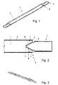
- a heat exchanger in the form of a brazed all-aluminum heat exchanger module according to the invention comprises a flat tube condenser, a coolant radiator comprising a plurality of flat tubes and corrugated fins interconnected in a network structure, and two opposing side members 1, one of which is in the Fig. 1 and 2 is shown.
- the side part 1 an aluminum sheet-metal bent part, has a substantially around the entire side part 1 circulating, by about 90 ° upwards, ie away from the flat tube condenser and coolant radiator, curved edge region 2.
- the edge region 2 is interrupted in an end region 3 of the side part 1 by two cutouts 4, which are arranged on both longitudinal sides of the side part 1 and have two edges 5 and 5 '. In this case, the edge further away from the end region 3 is denoted by 5 and the edge lying closer to the end region 3 is denoted by 5 '.
- the edge 5 Slightly spaced from the edge 5 is approximately symmetrically formed in each case an obliquely to the longitudinal axis of the side part 1 inwardly extending cutout 6 is provided, so that the two cutouts 6 are arranged in a V-shape.
- the end region 3 and the central region of the side part 1 are connected to each other by means of three webs 7.
- the webs 7 have a width of about 1.5 to 2 mm and form a predetermined breaking point 8.
- the cutouts 4 and 6 are arranged such that in each case at least one sharp-edged corner region of the cutouts 4 and 6 defines a web 7, so that a high notch effect is achieved and thus already at relatively low voltages the breaking point 8 breaks.
Landscapes
- Engineering & Computer Science (AREA)
- Physics & Mathematics (AREA)
- Thermal Sciences (AREA)
- Mechanical Engineering (AREA)
- General Engineering & Computer Science (AREA)
- Heat-Exchange Devices With Radiators And Conduit Assemblies (AREA)
- Details Of Heat-Exchange And Heat-Transfer (AREA)
- Air-Conditioning For Vehicles (AREA)
Description
- Die Erfindung betrifft einen Wärmeübertrager, insbesondere ein Wärmeübertragermodul, für ein Kraftfahrzeug gemäß dem Oberbegriff des Anspruchs 1. Ein derartiger Wärmeübertrager ist bekannt aus
JP-A-11 325 783 - Bei Wärmeübertragern in Form eines Wärmeübertragermoduls, d.h. bei denen der Kondensator und der Kühlmittelkühler als eine Einheit über Wellrippen und Seitenteile miteinander verbunden sind, treten infolge von Temperaturwechseln und damit verbundenen zeitweise unterschiedlichen Temperaturniveaus im Wärmetauscher und Kühlmittelkühler Spannungen aufgrund der unterschiedlichen Wärme-Dehnungszustände auf, die zu Undichtheiten führen können. Ferner belasten die Temperaturwechsel und die damit verbundenen Spannungsänderungen die umgeformten Rohrenden der Flachrohre des Wärmeübertragermoduls, was auch hier zu Undichtheit führen kann.
- Aus diesem Grund sind bei herkömmlichen Wärmeübertragern Dehnungssicken im Seitenteil vorgesehen, wie bspw. in
Fig. 3 im durch einen Kreis hervorgehobenen Bereich dargestellt ist. Die Herstellung derartiger Dehnungssicken erfordert spezielle Umformwerkzeuge sowie einen zusätzlichen Verbrauch an Material infolge der ausgeformten Sicken. - Es ist Aufgabe der Erfindung, einen derartigen Wärmeübertrager zu verbessern.
- Diese Aufgabe wird gelöst durch einen Wärmeübertrager mit den Merkmalen des Anspruchs 1.
- Erfindungsgemäß ist ein Wärmeübertrager für ein Kraftfahrzeug mit einem Wärmeübertragermodul, vorgesehen, der ein Seitenteil mit mindestens einer Sollbruchstelle aufweist. Dabei liegt die Sollbruchstelle vorzugsweise im Bereich der Rohrumformung oder an einer Schnittstelle zwischen dem Kondensatorteil (insbesondere Flachrohr-Kondensator) und dem Kühlmittelkühlteil (insbesondere Kühlmittelkühler) des Wärmeübertragermoduls.
- Vorzugsweise wird die Sollburchstelle durch Stege, insbesondere durch drei Stege, die mittels V-förmig angeordneter Ausschnitte voneinander getrennt sind, gebildet.
- Vorzugsweise weisen die Stege eine Breite von 0,5 bis 2 mm, insbesondere 1 bis 1,5 mm, auf, wodurch die Sollbruchstelle bereits bei relativ geringen Belastungen bricht und die Flachrohre des Wärmetauschers geschützt werden.
- Vorzugsweise ist der Wärmeübertrager derart ausgebildet, dass ein Randbereich des Seitenteiles um ca. 90° entlang der Längskante des Seitenteiles gebogen und im Bereich der Sollbruchstelle durch Ausschnitte unterbrochen ist.
- Vorzugsweise werden die Stege seitlich von Ausschnitten begrenzt, von denen mindestens einer in Richtung der Stege kantig, insbesondere mit einem Winkel von 90° oder weniger, d.h. scharfkantig, ausgebildet ist.
- Im folgenden wird die Erfindung anhand eines Ausführungsbeispiels unter Bezugnahme auf die Zeichnung im einzelnen erläutert. In der Zeichnung zeigen:
- Fig. 1
- eine perspektivische Darstellung eines Seitenteiles eines Wärmeübertragermoduls;
- Fig. 2
- eine Draufsicht auf einen Endbereich des Seitenteils von
Fig. 1 ; und - Fig. 3
- eine perspektivische Darstellung eines Seitenteiles eines Wärmeübertragermoduls gemäß dem Stand der Technik.
- Ein erfindungsgemäßer Wärmeübertrager in Form eines gelöteten Ganzaluminium-Wärmeübertragermoduls weist einen Flachrohr-Kondensator, einen Kühlmittelkühler, welche eine Mehrzahl von in Art einer Netzstruktur miteinander verbundenen Flachrohren und Wellrippen umfassen, und zwei einander gegenüberliegende Seitenteile 1 auf, wovon eines in den
Fig. 1 und 2 dargestellt ist. - Im folgenden wird auf
Fig. 2 Bezug genommen, wobei die Ausgestaltung der Seitenteile 1 an beiden Enden im wesentlichen symmetrisch ist. Das Seitenteil 1, ein Aluminium-Blechbiegeteil, weist einen im wesentlichen um das ganze Seitenteil 1 umlaufenden, um ca. 90° nach oben, d.h. weg vom Flachrohr-Kondensator und Kühlmittelkühler, gebogenen Randbereich 2 auf. Der Randbereich 2 ist in einem Endbereich 3 des Seitenteils 1 von zwei Ausschnitten 4 unterbrochen, die auf beiden Längsseiten des Seitenteils 1 angeordnet sind und zwei Kanten 5 und 5' aufweisen. Hierbei wird die vom Endbereich 3 weiter entfernt angeordnete Kante mit 5 und die näher am Endbereich 3 liegende Kante mit 5' bezeichnet. Etwas beabstandet von der Kante 5 ist etwa symmetrisch ausgebildet jeweils ein schräg zur Längsachse des Seitenteils 1 nach innen verlaufender Ausschnitt 6 vorgesehen, so dass die beiden Ausschnitte 6 V-förmig angeordnet sind. Der Endbereich 3 und der mittlere Bereich des Seitenteils 1 sind mittels dreier Stege 7 miteinander verbunden. Die Stege 7 weisen eine Breite von ca. 1,5 bis 2 mm auf und bilden eine Sollbruchstelle 8. Hierbei sind die Ausschnitte 4 und 6 derart angeordnet, dass jeweils mindestens ein scharfkantig ausgebildeter Eckbereich der Ausschnitte 4 bzw. 6 einen Steg 7 begrenzt, so dass eine hohe Kerbwirkung erzielt wird und dadurch bereits bei relativ kleinen Spannungen die Sollbruchstelle 8 bricht. Dies erfolgt insbesondere bei einer Temperaturänderung, infolge der sich die Kühlmittel-Flachrohre, in Richtung der Blockhöhe, d.h. in Längsrichtung des Seitenteils, ausdehnen und dadurch besagte Spannung am Seitenteil auftritt und zu einem Sollbruch führt, wodurch die Kühlmittel-Flachrohre entlastet werden. Dabei ist das Seitenteil in Richtung der Blockbreite sehr stabil, so dass die Sollbruchstelle keinen Einfluss auf das Spannen (Kassettieren) des Wärmeübertragermoduls hat. -
- 1
- Seitenteil
- 2
- Randbereich
- 3
- Endbereich
- 4
- Ausschnitt
- 5,
- 5' Kante
- 6
- Ausschnitt
- 7
- Steg
- 8
- Sollbruchstelle
Claims (8)
- Wärmeüberträger für ein Kraftfahrzeug, der eine Mehrzahl von nach Art einer Netzstruktur miteinander verbundenen Rohren und Wellrippen aufweist, sowie mit zwei Seitenteilen (1), die die Rohre und Wellrippen auf gegenübediegenden Seiten einfassen, wobei an einem Seitenteil (1) mindestens eine Sollbruchstelle (8) vorgesehen ist, dadurch gekennzeichnet, dass die Sollbruchstelle (8) durch Stege (7) gebildet wird, welche seitlich von Ausschnitten (4, 6) begrenzt werden, von denen mindestens einer in Richtung der Stege (7) kantig ausgebildet ist.
- Wärmeübertrager nach Anspruch 1, dadurch gekennzeichnet, dass die Sollbruchstelle (8) im Bereich einer Rohrumformung angeordnet ist.
- Wärmeübertrager nach Anspruch 1, dadurch gekennzeichnet, dass der Wärmeübertrager ein Wärmeübertragermodul mit einem Kondensatorteil und einem Kühlmittelkühlteil aufweist, und dass die Sollbruchstelle (8) an einer Schnittstelle zwischen dem Kondensatorteil und dem Kühlmittelkühlteil angeordnet ist.
- Wärmeübertrager nach einem der vorhergehenden Ansprüche, dadurch gekennzeichnet, dass die Sollbruchstelle (8) V-förmig ausgebildet ist.
- Wärmeübertrager nach Anspruch 4, dadurch gekennzeichnet, dass die Stege (7) an den drei Ecken der V-förmigen Sollbruchstelle (8) angeordnet sind.
- Wärmeübertrager nach Anspruch 5, dadurch gekennzeichnet, dass die Stege (7) eine Breite von 0,5 bis 2 mm, insbesondere 1 bis 1,5 mm, aufweisen.
- Wärmeübertrager nach einem der vorhergehenden Ansprüche, dadurch gekennzeichnet, dass ein Randbereich (2) des Seitenteiles (1) um ca. 90° entlang der Längskante des Seitenteiles (1) gebogen und im Bereich der Sollbruchstelle (8) durch Ausschnitte (4) unterbrochen ist.
- Wärmeübertrager nach einem der vorhergehenden Ansprüche, dadurch gekennzeichnet, dass die Ausschnitte (4, 6) mindestens eine Kante (5) aufweisen, welche einen Winkel von 90° oder weniger aufweist.
Applications Claiming Priority (3)
| Application Number | Priority Date | Filing Date | Title |
|---|---|---|---|
| DE10218048 | 2002-04-23 | ||
| DE10218048A DE10218048A1 (de) | 2002-04-23 | 2002-04-23 | Wärmeübertrager, insbesondere Wärmeübertragermodul, für ein Kraftfahrzeug |
| PCT/EP2003/003771 WO2003091649A1 (de) | 2002-04-23 | 2003-04-11 | Wärmeübertrager, insbesondere wärmeübertragermodul, für ein kraftfahrzeug |
Publications (2)
| Publication Number | Publication Date |
|---|---|
| EP1502068A1 EP1502068A1 (de) | 2005-02-02 |
| EP1502068B1 true EP1502068B1 (de) | 2009-07-01 |
Family
ID=29224675
Family Applications (1)
| Application Number | Title | Priority Date | Filing Date |
|---|---|---|---|
| EP03732278A Expired - Lifetime EP1502068B1 (de) | 2002-04-23 | 2003-04-11 | Wärmeübertrager, insbesondere wä rmeübertragermodul, für ein kraftfahrzeug |
Country Status (9)
| Country | Link |
|---|---|
| US (1) | US7198095B2 (de) |
| EP (1) | EP1502068B1 (de) |
| JP (1) | JP2005524043A (de) |
| CN (1) | CN100356131C (de) |
| AT (1) | ATE435411T1 (de) |
| AU (1) | AU2003239803A1 (de) |
| BR (1) | BR0304662A (de) |
| DE (2) | DE10218048A1 (de) |
| WO (1) | WO2003091649A1 (de) |
Cited By (2)
| Publication number | Priority date | Publication date | Assignee | Title |
|---|---|---|---|---|
| DE102017206113A1 (de) | 2017-04-10 | 2018-10-11 | Mahle International Gmbh | Wärmeübertrager für ein Kraftfahrzeug |
| DE102018213676A1 (de) * | 2018-08-14 | 2020-02-20 | Mahle International Gmbh | Wärmeübertrager für ein Kraftfahrzeug und ein Verfahren zum Herstellen des Wärmeübertragers |
Families Citing this family (21)
| Publication number | Priority date | Publication date | Assignee | Title |
|---|---|---|---|---|
| DE10333150A1 (de) * | 2003-07-22 | 2005-02-17 | Modine Manufacturing Co., Racine | Wärmeaustauscher für Kraftfahrzeuge |
| EP1716378B1 (de) * | 2004-02-02 | 2008-02-20 | Behr GmbH & Co. KG | Seitenblech für kühler |
| DE102004013383A1 (de) * | 2004-03-17 | 2005-10-06 | Behr Gmbh & Co. Kg | Röhrenwärmetauscher |
| DE102004036019A1 (de) * | 2004-07-23 | 2006-02-16 | Behr Gmbh & Co. Kg | Kühler, insbesondere Kühler für Fahrzeuge |
| US20070256819A1 (en) * | 2004-09-15 | 2007-11-08 | Behr Gmbh & Co. Kg | Metal Side-Plate for a Radiator |
| JP4604759B2 (ja) * | 2005-02-22 | 2011-01-05 | 株式会社デンソー | 熱交換器 |
| US20080190596A1 (en) * | 2005-04-05 | 2008-08-14 | Dieter Bachner | Heat Exchanger, in Particular for a Motor Vehicle |
| US7594327B2 (en) * | 2005-04-11 | 2009-09-29 | Modine Manufacturing Company | Heat exchanger and method of making the same |
| ES2302323T3 (es) * | 2005-06-11 | 2008-07-01 | Modine Manufacturing Company | Intercambiadores de calor enteramente metalico y procedimiento para su fabricacion. |
| US20100032149A1 (en) * | 2006-07-08 | 2010-02-11 | Helmut Roll | Heat exchanger and method of manufacturing the same |
| JP2008020085A (ja) * | 2006-07-10 | 2008-01-31 | Denso Corp | 熱交換器 |
| US9309839B2 (en) | 2010-03-18 | 2016-04-12 | Modine Manufacturing Company | Heat exchanger and method of manufacturing the same |
| AU2011201083B2 (en) | 2010-03-18 | 2013-12-05 | Modine Manufacturing Company | Heat exchanger and method of manufacturing the same |
| CN102285313A (zh) * | 2011-02-23 | 2011-12-21 | 泰安鼎鑫冷却器有限公司 | 用于汽车换热器的护板 |
| DE102011082797A1 (de) * | 2011-09-15 | 2013-03-21 | Behr Gmbh & Co. Kg | Wärmeübertrager zum Kühlen von Ladeluft |
| JP6262982B2 (ja) * | 2013-10-11 | 2018-01-17 | 三菱重工サーマルシステムズ株式会社 | 熱交換器 |
| MX2016005352A (es) * | 2013-10-23 | 2016-08-11 | Modine Mfg Co | Intercambiador de calor y placa lateral. |
| JP7433885B2 (ja) * | 2019-12-20 | 2024-02-20 | 株式会社ティラド | 熱交換器コアのサポート構造 |
| US20210381778A1 (en) * | 2020-06-04 | 2021-12-09 | Denso International America, Inc. | Heat exchanger with thermal stress-relief areas |
| CN112902731B (zh) * | 2021-03-02 | 2022-05-27 | 浙江银轮机械股份有限公司 | 侧板、换热芯体及换热器 |
| DE102023200937A1 (de) * | 2023-02-06 | 2024-08-08 | Mahle International Gmbh | Thermomanagementmodul |
Family Cites Families (13)
| Publication number | Priority date | Publication date | Assignee | Title |
|---|---|---|---|---|
| US1357597A (en) * | 1918-07-12 | 1920-11-02 | Springer John | Frame for radiators |
| DE2856031C2 (de) * | 1978-12-23 | 1986-07-03 | Süddeutsche Kühlerfabrik Julius Fr. Behr GmbH & Co KG, 7000 Stuttgart | Heizkörpergehäuse für Kraftfahrzeuge |
| US4719967A (en) * | 1987-06-22 | 1988-01-19 | General Motors Corporation | Heat exchanger core with shearable reinforcements |
| US5257454A (en) * | 1992-01-30 | 1993-11-02 | Ford Motor Company | Method of making a heat exchanger with thermal stress relieving zone |
| US5186239A (en) * | 1992-01-30 | 1993-02-16 | Ford Motor Company | Heat exchanger with thermal stress relieving zone |
| DE4309356A1 (de) * | 1993-03-23 | 1994-09-29 | Behr Gmbh & Co | Gehäuse aus Kunststoff für eine Heizungs- oder Klimaanlage eines Kraftfahrzeuges |
| US5931223A (en) * | 1995-04-28 | 1999-08-03 | Ford Motor Company | Heat exchanger with thermal stress relieving zone |
| GB2303437A (en) * | 1995-06-12 | 1997-02-19 | Ford Motor Co | Stress relief in heat exchangers |
| US6129142A (en) * | 1997-12-18 | 2000-10-10 | Alliedsignal Inc. | Radiator thermal expansion joint and method for making the same |
| JPH11325783A (ja) * | 1998-05-20 | 1999-11-26 | Showa Alum Corp | 熱交換器及びその製造方法 |
| US6328098B1 (en) * | 1998-11-10 | 2001-12-11 | Valeo Inc. | Side member for heat exchanger and heat exchanger incorporating side plate |
| JP2002147973A (ja) * | 2000-08-30 | 2002-05-22 | Denso Corp | 複式熱交換器 |
| US6412547B1 (en) * | 2000-10-04 | 2002-07-02 | Modine Manufacturing Company | Heat exchanger and method of making the same |
-
2002
- 2002-04-23 DE DE10218048A patent/DE10218048A1/de not_active Withdrawn
-
2003
- 2003-04-11 DE DE50311662T patent/DE50311662D1/de not_active Expired - Lifetime
- 2003-04-11 US US10/510,102 patent/US7198095B2/en not_active Expired - Lifetime
- 2003-04-11 JP JP2003588147A patent/JP2005524043A/ja active Pending
- 2003-04-11 AU AU2003239803A patent/AU2003239803A1/en not_active Abandoned
- 2003-04-11 WO PCT/EP2003/003771 patent/WO2003091649A1/de not_active Ceased
- 2003-04-11 CN CNB038091615A patent/CN100356131C/zh not_active Expired - Fee Related
- 2003-04-11 EP EP03732278A patent/EP1502068B1/de not_active Expired - Lifetime
- 2003-04-11 AT AT03732278T patent/ATE435411T1/de not_active IP Right Cessation
- 2003-04-11 BR BR0304662-1A patent/BR0304662A/pt not_active IP Right Cessation
Cited By (3)
| Publication number | Priority date | Publication date | Assignee | Title |
|---|---|---|---|---|
| DE102017206113A1 (de) | 2017-04-10 | 2018-10-11 | Mahle International Gmbh | Wärmeübertrager für ein Kraftfahrzeug |
| US10914536B2 (en) | 2017-04-10 | 2021-02-09 | Mahle International Gmbh | Heat exchanger for a motor vehicle |
| DE102018213676A1 (de) * | 2018-08-14 | 2020-02-20 | Mahle International Gmbh | Wärmeübertrager für ein Kraftfahrzeug und ein Verfahren zum Herstellen des Wärmeübertragers |
Also Published As
| Publication number | Publication date |
|---|---|
| BR0304662A (pt) | 2005-07-05 |
| WO2003091649A1 (de) | 2003-11-06 |
| CN1653310A (zh) | 2005-08-10 |
| DE50311662D1 (de) | 2009-08-13 |
| DE10218048A1 (de) | 2003-11-13 |
| US20050121178A1 (en) | 2005-06-09 |
| JP2005524043A (ja) | 2005-08-11 |
| EP1502068A1 (de) | 2005-02-02 |
| US7198095B2 (en) | 2007-04-03 |
| AU2003239803A1 (en) | 2003-11-10 |
| CN100356131C (zh) | 2007-12-19 |
| ATE435411T1 (de) | 2009-07-15 |
Similar Documents
| Publication | Publication Date | Title |
|---|---|---|
| DE10218048A1 (de) | Wärmeübertrager, insbesondere Wärmeübertragermodul, für ein Kraftfahrzeug | |
| DE69915776T3 (de) | Seitenteil für Wärmetauscher und Wärmetauscher mit Seitenplatten | |
| WO2003085348A1 (de) | Wärmeübertragereinheit, insbesondere für ein kraftfahrzeug | |
| DE60219538T2 (de) | Wärmetauscher | |
| DE69008681T2 (de) | Duplex-Wärmetauscher. | |
| DE19753408B4 (de) | Wärmeübertrager für ein Kraftfahrzeug | |
| EP1616143B1 (de) | Wärmeübertrager, insbesondere ladeluftkühler für kraftfahrzeuge | |
| DE69814717T2 (de) | Wärmetauscher mit mehreren Wärmeaustauschteilen | |
| EP0547309A1 (de) | Wellrippe für Flachrohrwärmetauscher | |
| DE102015209130A1 (de) | Wärmeübertrager | |
| WO2004048874A1 (de) | Värmeübertragereinheit, insbesondere für ein kraftfahrzeug, und verfahren zur herstellung | |
| EP1306640B1 (de) | Rohrboden für Abgaswärmeübertragung | |
| DE102015209858B4 (de) | Plattenwärmetauscher | |
| EP2909562B1 (de) | Wärmetauscher | |
| DE69718343T2 (de) | Wärmetauscher für klimaanlage | |
| DE19814028A1 (de) | Doppel-Wärmetauscher | |
| WO2005028986A1 (de) | Gelötetes wärmeübertragernetz | |
| DE602006000675T2 (de) | Wellrippe für integralgefertigten Wärmetäuscher | |
| DE10255011A1 (de) | Wärmeübertragereinheit, insbesondere für ein Kraftfahrzeug | |
| WO2004079748A2 (de) | Abstandhalter | |
| WO2006105925A1 (de) | Wärmeübertrager, insbesondere für ein kraftfahrzeug | |
| DE102005043291A1 (de) | Seitenblech für Kühler | |
| EP1774242B1 (de) | Kühler, insbesondere kühler für fahrzeuge | |
| DE102018113339A1 (de) | Batteriekühlvorrichtung zur Kühlung einer Batterie, insbesondere der Batterie eines Kraftfahrzeugs bzw. Anordnungsstruktur mit mindestens einer Batterie, insbesondere einer Batterie eines Kraftfahrzeugs und mit der zuvor genannten Batteriekühlvorrichtung | |
| DE102016103226A1 (de) | Rohrbündel, Rohrbündelwärmetauscher und Verfahren zu deren Herstellung |
Legal Events
| Date | Code | Title | Description |
|---|---|---|---|
| PUAI | Public reference made under article 153(3) epc to a published international application that has entered the european phase |
Free format text: ORIGINAL CODE: 0009012 |
|
| 17P | Request for examination filed |
Effective date: 20041123 |
|
| AK | Designated contracting states |
Kind code of ref document: A1 Designated state(s): AT BE BG CH CY CZ DE DK EE ES FI FR GB GR HU IE IT LI LU MC NL PT RO SE SI SK TR |
|
| AX | Request for extension of the european patent |
Extension state: AL LT LV MK |
|
| 17Q | First examination report despatched |
Effective date: 20080828 |
|
| GRAP | Despatch of communication of intention to grant a patent |
Free format text: ORIGINAL CODE: EPIDOSNIGR1 |
|
| GRAS | Grant fee paid |
Free format text: ORIGINAL CODE: EPIDOSNIGR3 |
|
| GRAA | (expected) grant |
Free format text: ORIGINAL CODE: 0009210 |
|
| AK | Designated contracting states |
Kind code of ref document: B1 Designated state(s): AT BE BG CH CY CZ DE DK EE ES FI FR GB GR HU IE IT LI LU MC NL PT RO SE SI SK TR |
|
| REG | Reference to a national code |
Ref country code: GB Ref legal event code: FG4D Free format text: NOT ENGLISH |
|
| REG | Reference to a national code |
Ref country code: CH Ref legal event code: EP |
|
| REG | Reference to a national code |
Ref country code: IE Ref legal event code: FG4D |
|
| REF | Corresponds to: |
Ref document number: 50311662 Country of ref document: DE Date of ref document: 20090813 Kind code of ref document: P |
|
| PG25 | Lapsed in a contracting state [announced via postgrant information from national office to epo] |
Ref country code: SI Free format text: LAPSE BECAUSE OF FAILURE TO SUBMIT A TRANSLATION OF THE DESCRIPTION OR TO PAY THE FEE WITHIN THE PRESCRIBED TIME-LIMIT Effective date: 20090701 |
|
| NLV1 | Nl: lapsed or annulled due to failure to fulfill the requirements of art. 29p and 29m of the patents act | ||
| PG25 | Lapsed in a contracting state [announced via postgrant information from national office to epo] |
Ref country code: ES Free format text: LAPSE BECAUSE OF FAILURE TO SUBMIT A TRANSLATION OF THE DESCRIPTION OR TO PAY THE FEE WITHIN THE PRESCRIBED TIME-LIMIT Effective date: 20091012 Ref country code: EE Free format text: LAPSE BECAUSE OF FAILURE TO SUBMIT A TRANSLATION OF THE DESCRIPTION OR TO PAY THE FEE WITHIN THE PRESCRIBED TIME-LIMIT Effective date: 20090701 Ref country code: SE Free format text: LAPSE BECAUSE OF FAILURE TO SUBMIT A TRANSLATION OF THE DESCRIPTION OR TO PAY THE FEE WITHIN THE PRESCRIBED TIME-LIMIT Effective date: 20090701 Ref country code: FI Free format text: LAPSE BECAUSE OF FAILURE TO SUBMIT A TRANSLATION OF THE DESCRIPTION OR TO PAY THE FEE WITHIN THE PRESCRIBED TIME-LIMIT Effective date: 20090701 |
|
| REG | Reference to a national code |
Ref country code: IE Ref legal event code: FD4D |
|
| PG25 | Lapsed in a contracting state [announced via postgrant information from national office to epo] |
Ref country code: NL Free format text: LAPSE BECAUSE OF FAILURE TO SUBMIT A TRANSLATION OF THE DESCRIPTION OR TO PAY THE FEE WITHIN THE PRESCRIBED TIME-LIMIT Effective date: 20090701 |
|
| PG25 | Lapsed in a contracting state [announced via postgrant information from national office to epo] |
Ref country code: PT Free format text: LAPSE BECAUSE OF FAILURE TO SUBMIT A TRANSLATION OF THE DESCRIPTION OR TO PAY THE FEE WITHIN THE PRESCRIBED TIME-LIMIT Effective date: 20091102 Ref country code: BG Free format text: LAPSE BECAUSE OF FAILURE TO SUBMIT A TRANSLATION OF THE DESCRIPTION OR TO PAY THE FEE WITHIN THE PRESCRIBED TIME-LIMIT Effective date: 20091001 |
|
| PG25 | Lapsed in a contracting state [announced via postgrant information from national office to epo] |
Ref country code: CZ Free format text: LAPSE BECAUSE OF FAILURE TO SUBMIT A TRANSLATION OF THE DESCRIPTION OR TO PAY THE FEE WITHIN THE PRESCRIBED TIME-LIMIT Effective date: 20090701 Ref country code: RO Free format text: LAPSE BECAUSE OF FAILURE TO SUBMIT A TRANSLATION OF THE DESCRIPTION OR TO PAY THE FEE WITHIN THE PRESCRIBED TIME-LIMIT Effective date: 20090701 Ref country code: IE Free format text: LAPSE BECAUSE OF FAILURE TO SUBMIT A TRANSLATION OF THE DESCRIPTION OR TO PAY THE FEE WITHIN THE PRESCRIBED TIME-LIMIT Effective date: 20090701 Ref country code: DK Free format text: LAPSE BECAUSE OF FAILURE TO SUBMIT A TRANSLATION OF THE DESCRIPTION OR TO PAY THE FEE WITHIN THE PRESCRIBED TIME-LIMIT Effective date: 20090701 |
|
| PLBE | No opposition filed within time limit |
Free format text: ORIGINAL CODE: 0009261 |
|
| STAA | Information on the status of an ep patent application or granted ep patent |
Free format text: STATUS: NO OPPOSITION FILED WITHIN TIME LIMIT |
|
| PG25 | Lapsed in a contracting state [announced via postgrant information from national office to epo] |
Ref country code: SK Free format text: LAPSE BECAUSE OF FAILURE TO SUBMIT A TRANSLATION OF THE DESCRIPTION OR TO PAY THE FEE WITHIN THE PRESCRIBED TIME-LIMIT Effective date: 20090701 |
|
| 26N | No opposition filed |
Effective date: 20100406 |
|
| PGFP | Annual fee paid to national office [announced via postgrant information from national office to epo] |
Ref country code: FR Payment date: 20100428 Year of fee payment: 8 |
|
| PG25 | Lapsed in a contracting state [announced via postgrant information from national office to epo] |
Ref country code: GR Free format text: LAPSE BECAUSE OF FAILURE TO SUBMIT A TRANSLATION OF THE DESCRIPTION OR TO PAY THE FEE WITHIN THE PRESCRIBED TIME-LIMIT Effective date: 20091002 |
|
| BERE | Be: lapsed |
Owner name: BEHR G.M.B.H. & CO. KG Effective date: 20100430 |
|
| PG25 | Lapsed in a contracting state [announced via postgrant information from national office to epo] |
Ref country code: MC Free format text: LAPSE BECAUSE OF NON-PAYMENT OF DUE FEES Effective date: 20100430 |
|
| REG | Reference to a national code |
Ref country code: CH Ref legal event code: PL |
|
| GBPC | Gb: european patent ceased through non-payment of renewal fee |
Effective date: 20100411 |
|
| PG25 | Lapsed in a contracting state [announced via postgrant information from national office to epo] |
Ref country code: CH Free format text: LAPSE BECAUSE OF NON-PAYMENT OF DUE FEES Effective date: 20100430 Ref country code: LI Free format text: LAPSE BECAUSE OF NON-PAYMENT OF DUE FEES Effective date: 20100430 |
|
| PG25 | Lapsed in a contracting state [announced via postgrant information from national office to epo] |
Ref country code: IT Free format text: LAPSE BECAUSE OF FAILURE TO SUBMIT A TRANSLATION OF THE DESCRIPTION OR TO PAY THE FEE WITHIN THE PRESCRIBED TIME-LIMIT Effective date: 20090701 Ref country code: GB Free format text: LAPSE BECAUSE OF NON-PAYMENT OF DUE FEES Effective date: 20100411 Ref country code: BE Free format text: LAPSE BECAUSE OF NON-PAYMENT OF DUE FEES Effective date: 20100430 |
|
| PG25 | Lapsed in a contracting state [announced via postgrant information from national office to epo] |
Ref country code: AT Free format text: LAPSE BECAUSE OF NON-PAYMENT OF DUE FEES Effective date: 20100411 |
|
| REG | Reference to a national code |
Ref country code: FR Ref legal event code: ST Effective date: 20111230 |
|
| PG25 | Lapsed in a contracting state [announced via postgrant information from national office to epo] |
Ref country code: FR Free format text: LAPSE BECAUSE OF NON-PAYMENT OF DUE FEES Effective date: 20110502 |
|
| PG25 | Lapsed in a contracting state [announced via postgrant information from national office to epo] |
Ref country code: CY Free format text: LAPSE BECAUSE OF FAILURE TO SUBMIT A TRANSLATION OF THE DESCRIPTION OR TO PAY THE FEE WITHIN THE PRESCRIBED TIME-LIMIT Effective date: 20090701 |
|
| PG25 | Lapsed in a contracting state [announced via postgrant information from national office to epo] |
Ref country code: HU Free format text: LAPSE BECAUSE OF FAILURE TO SUBMIT A TRANSLATION OF THE DESCRIPTION OR TO PAY THE FEE WITHIN THE PRESCRIBED TIME-LIMIT Effective date: 20100102 Ref country code: LU Free format text: LAPSE BECAUSE OF NON-PAYMENT OF DUE FEES Effective date: 20100411 |
|
| PG25 | Lapsed in a contracting state [announced via postgrant information from national office to epo] |
Ref country code: TR Free format text: LAPSE BECAUSE OF FAILURE TO SUBMIT A TRANSLATION OF THE DESCRIPTION OR TO PAY THE FEE WITHIN THE PRESCRIBED TIME-LIMIT Effective date: 20090701 |
|
| REG | Reference to a national code |
Ref country code: DE Ref legal event code: R082 Ref document number: 50311662 Country of ref document: DE Representative=s name: GRAUEL, ANDREAS, DIPL.-PHYS. DR. RER. NAT., DE |
|
| REG | Reference to a national code |
Ref country code: DE Ref legal event code: R082 Ref document number: 50311662 Country of ref document: DE Representative=s name: GRAUEL, ANDREAS, DIPL.-PHYS. DR. RER. NAT., DE Effective date: 20150223 Ref country code: DE Ref legal event code: R081 Ref document number: 50311662 Country of ref document: DE Owner name: MAHLE INTERNATIONAL GMBH, DE Free format text: FORMER OWNER: BEHR GMBH & CO. KG, 70469 STUTTGART, DE Effective date: 20150223 |
|
| PGFP | Annual fee paid to national office [announced via postgrant information from national office to epo] |
Ref country code: DE Payment date: 20200630 Year of fee payment: 18 |
|
| REG | Reference to a national code |
Ref country code: DE Ref legal event code: R119 Ref document number: 50311662 Country of ref document: DE |
|
| PG25 | Lapsed in a contracting state [announced via postgrant information from national office to epo] |
Ref country code: DE Free format text: LAPSE BECAUSE OF NON-PAYMENT OF DUE FEES Effective date: 20211103 |