EP1616143B1 - Wärmeübertrager, insbesondere ladeluftkühler für kraftfahrzeuge - Google Patents
Wärmeübertrager, insbesondere ladeluftkühler für kraftfahrzeuge Download PDFInfo
- Publication number
- EP1616143B1 EP1616143B1 EP04722246A EP04722246A EP1616143B1 EP 1616143 B1 EP1616143 B1 EP 1616143B1 EP 04722246 A EP04722246 A EP 04722246A EP 04722246 A EP04722246 A EP 04722246A EP 1616143 B1 EP1616143 B1 EP 1616143B1
- Authority
- EP
- European Patent Office
- Prior art keywords
- tube
- heat exchanger
- passages
- short sides
- charge
- Prior art date
- Legal status (The legal status is an assumption and is not a legal conclusion. Google has not performed a legal analysis and makes no representation as to the accuracy of the status listed.)
- Expired - Lifetime
Links
- 230000007704 transition Effects 0.000 claims abstract description 20
- 230000002787 reinforcement Effects 0.000 claims description 4
- 230000003014 reinforcing effect Effects 0.000 abstract 1
- 239000003570 air Substances 0.000 description 16
- 238000005452 bending Methods 0.000 description 4
- 229910000838 Al alloy Inorganic materials 0.000 description 3
- 230000005499 meniscus Effects 0.000 description 3
- 229910000679 solder Inorganic materials 0.000 description 3
- 238000005476 soldering Methods 0.000 description 3
- 229910052782 aluminium Inorganic materials 0.000 description 2
- XAGFODPZIPBFFR-UHFFFAOYSA-N aluminium Chemical compound [Al] XAGFODPZIPBFFR-UHFFFAOYSA-N 0.000 description 2
- 238000004049 embossing Methods 0.000 description 2
- 238000003780 insertion Methods 0.000 description 2
- 230000037431 insertion Effects 0.000 description 2
- 229910052751 metal Inorganic materials 0.000 description 2
- 239000002184 metal Substances 0.000 description 2
- 239000002689 soil Substances 0.000 description 2
- 239000000243 solution Substances 0.000 description 2
- 230000001154 acute effect Effects 0.000 description 1
- 238000004026 adhesive bonding Methods 0.000 description 1
- 239000012080 ambient air Substances 0.000 description 1
- 238000005266 casting Methods 0.000 description 1
- 239000002826 coolant Substances 0.000 description 1
- 238000001816 cooling Methods 0.000 description 1
- 230000000694 effects Effects 0.000 description 1
- 238000002347 injection Methods 0.000 description 1
- 239000007924 injection Substances 0.000 description 1
- 238000004519 manufacturing process Methods 0.000 description 1
- 230000013011 mating Effects 0.000 description 1
- 238000000465 moulding Methods 0.000 description 1
- 230000002093 peripheral effect Effects 0.000 description 1
- 238000004080 punching Methods 0.000 description 1
- 239000007787 solid Substances 0.000 description 1
Images




Classifications
-
- F—MECHANICAL ENGINEERING; LIGHTING; HEATING; WEAPONS; BLASTING
- F28—HEAT EXCHANGE IN GENERAL
- F28F—DETAILS OF HEAT-EXCHANGE AND HEAT-TRANSFER APPARATUS, OF GENERAL APPLICATION
- F28F9/00—Casings; Header boxes; Auxiliary supports for elements; Auxiliary members within casings
- F28F9/02—Header boxes; End plates
- F28F9/0219—Arrangements for sealing end plates into casing or header box; Header box sub-elements
- F28F9/0224—Header boxes formed by sealing end plates into covers
-
- F—MECHANICAL ENGINEERING; LIGHTING; HEATING; WEAPONS; BLASTING
- F28—HEAT EXCHANGE IN GENERAL
- F28D—HEAT-EXCHANGE APPARATUS, NOT PROVIDED FOR IN ANOTHER SUBCLASS, IN WHICH THE HEAT-EXCHANGE MEDIA DO NOT COME INTO DIRECT CONTACT
- F28D1/00—Heat-exchange apparatus having stationary conduit assemblies for one heat-exchange medium only, the media being in contact with different sides of the conduit wall, in which the other heat-exchange medium is a large body of fluid, e.g. domestic or motor car radiators
- F28D1/02—Heat-exchange apparatus having stationary conduit assemblies for one heat-exchange medium only, the media being in contact with different sides of the conduit wall, in which the other heat-exchange medium is a large body of fluid, e.g. domestic or motor car radiators with heat-exchange conduits immersed in the body of fluid
- F28D1/04—Heat-exchange apparatus having stationary conduit assemblies for one heat-exchange medium only, the media being in contact with different sides of the conduit wall, in which the other heat-exchange medium is a large body of fluid, e.g. domestic or motor car radiators with heat-exchange conduits immersed in the body of fluid with tubular conduits
- F28D1/053—Heat-exchange apparatus having stationary conduit assemblies for one heat-exchange medium only, the media being in contact with different sides of the conduit wall, in which the other heat-exchange medium is a large body of fluid, e.g. domestic or motor car radiators with heat-exchange conduits immersed in the body of fluid with tubular conduits the conduits being straight
- F28D1/0535—Heat-exchange apparatus having stationary conduit assemblies for one heat-exchange medium only, the media being in contact with different sides of the conduit wall, in which the other heat-exchange medium is a large body of fluid, e.g. domestic or motor car radiators with heat-exchange conduits immersed in the body of fluid with tubular conduits the conduits being straight the conduits having a non-circular cross-section
-
- F—MECHANICAL ENGINEERING; LIGHTING; HEATING; WEAPONS; BLASTING
- F28—HEAT EXCHANGE IN GENERAL
- F28D—HEAT-EXCHANGE APPARATUS, NOT PROVIDED FOR IN ANOTHER SUBCLASS, IN WHICH THE HEAT-EXCHANGE MEDIA DO NOT COME INTO DIRECT CONTACT
- F28D21/00—Heat-exchange apparatus not covered by any of the groups F28D1/00 - F28D20/00
- F28D2021/0019—Other heat exchangers for particular applications; Heat exchange systems not otherwise provided for
- F28D2021/008—Other heat exchangers for particular applications; Heat exchange systems not otherwise provided for for vehicles
- F28D2021/0082—Charged air coolers
-
- F—MECHANICAL ENGINEERING; LIGHTING; HEATING; WEAPONS; BLASTING
- F28—HEAT EXCHANGE IN GENERAL
- F28F—DETAILS OF HEAT-EXCHANGE AND HEAT-TRANSFER APPARATUS, OF GENERAL APPLICATION
- F28F2225/00—Reinforcing means
- F28F2225/08—Reinforcing means for header boxes
Definitions
- the invention relates to a heat exchanger, in particular a charge air cooler for motor vehicles according to the preamble of claim 1.
- Intercooler and coolant radiator are made of aluminum (aluminum alloys) and soldered, either only the heat exchanger block or the entire heat exchanger including manifolds.
- the heat exchanger block, especially in intercoolers is constructed from a series of flat tubes, between which corrugated fins are arranged.
- the tube ends of the flat tubes are received in openings, so-called passages of the tubesheet and are soldered to the passages. This creates a solid and tight pipe / floor connection.
- the collection boxes are soldered or welded to the tubes.
- the tube plate has a peripheral edge strip, which extends over or under the collecting box and thus forms a soldering surface.
- the passages in the tube sheet extend over its entire depth, ie from longitudinal side to longitudinal side, wherein between the narrow sides of the passages and the edge strips a transition region exists, the trough-like, z. B. is formed approximately U-shaped.
- the tube sheet thus has an approximately rectangular-shaped, possibly circumferential groove, which is composed of two parallel longitudinal and two parallel narrow sides.
- the long sides of the tube bottom are opposite to the narrow sides of the passages.
- the headers are characterized by the internal pressure of the heat transfer medium, z. B. charged charge air.
- the pipe / floor connection is claimed on its narrow side and in the pipes corner areas by these stresses and deformations so that it can lead to leaks in the heat exchanger.
- EP 791 797 A is a heat exchanger described according to the preamble of patent claim 1.
- a reinforcement is provided in the transition region of the tubesheet.
- the tubesheet which has approximately the same wall thickness in the remaining area due to its production from a sheet metal blank, is therefore less deformable on the longitudinal sides in the region of the narrow sides of the tube. This will be the Pipe / soil connection less or hardly on bending, but essentially stressed on thrust, which is a much cheaper load.
- the reinforcement is designed as an inserted profiled strip which at least partially fills the channel-like transitional area and conforms to narrow sides of the passages, and is preferably soldered to the tube sheet.
- This profile strip gain is achieved, through an additional part, which is connected to the tubesheet to a rigid area.
- a connection ie a fixed bridge is provided which prevents deflection or deformation of the transition region.
- the profile strip is designed as a (separate) Einlege advisor, d. H. an additional part, which is inserted into the channel-like transition region and soldered to the tube bottom.
- Einlege advisorn can be used for heat exchangers, especially intercooler, which are to be used for higher charge air pressures.
- intercooler which are to be used for higher charge air pressures.
- the same cooler can be adapted to the higher operating stresses with this simple, targeted measure.
- the corner regions of the tubes are protected from harmful voltage spikes.
- Fig. 1 shows a section, ie a "disc” of a charge air cooler in the area of the charge air box and the pipe / floor connection.
- Such intercoolers are used for the cooling of compressed charge air in motor vehicles, especially commercial vehicles.
- a collection box 1 (also called charge air box) is formed in cross-section U-shaped and preferably made of an aluminum alloy. Overall, the collection box 1 in the form of an elongated box, which can be made by deep drawing or casting.
- the U-profile of the header tank 1 has two legs 2, 3, which form the longitudinal sides of the charge air box.
- the collecting tank 1 is inserted into a tube plate 4, the longitudinal side edges 5, 6, which are angled approximately perpendicular to a bottom plate 7.
- the bottom plate 7 has a plurality of passages, of which only a passage 8 is shown here, which receives a pipe end 9a of a flat tube 9.
- the entire heat transfer or intercooler thus has a plurality of flat tubes, between which corrugated fins, not shown, are arranged, which form secondary heat exchange surfaces for ambient air.
- the legs 2, 3 of the box profile have at their lower, ie open side connecting portions 2a, 3a, which overlap with the edge strips 5, 6 of the tube plate 4 and are soldered together in this area. Below the lower edges of the connecting portions 2a, 3a are shown hatched, so-called Einlege advisorn 10, 11 are arranged.
- Fig. 2 shows the collection box 1 according to Fig. 1 as a view, ie in a sectional plane before the passage 8.
- the tube sheet 4 is - as known from the prior art - made of a sheet metal blank and therefore essentially has a constant wall thickness s; the passages 8 are directed inwards, ie towards the side of the box 1.
- the tubes 9 are with their tube ends 9a inwardly beyond the passage 8 addition.
- the passages directed to the outside.
- the tubes can project beyond a tube bottom surface or advantageously end below such a tube bottom surface.
- the flat bottom plate 7 is on the longitudinal sides of the tube sheet 4, d. H. outside of the passages 8, but within the edge strips 5, 6 channel-like design, said groove passes on the one hand in the bottom plate 7 and on the other hand, in the edge strips 5, 6, d. H. Transition areas 12, 13 forms. Due to the loading of the box 1 by the internal pressure caused by the compressed charge air, pressure and / or tensile forces develop in the longitudinal sides 2, 3 of the box 1, which are transmitted to the edge strips 5, 6 of the soil and in the transition regions 12, 13 cause bending stresses and deformations.
- the invention by the arrangement of the Einlegemannn 10, 11, which are designed as profile strips and have a profile which corresponds to that of the transition regions 12, 13.
- the Einlegeorn 10, 11 are thus outside of the edge strips 5, 6, down to the channel-like transitional areas 12, 13 and inside of the narrow sides of the passages 8 at. Above the edge strips 10, 11 air gaps 14, 15 are left.
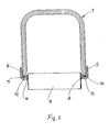
- Fig. 3 shows a sectional view in a plane parallel to the plane according to Fig. 2 ,
- the passages 8 are clearly visible in their profile: the passages 8 form with the outer wall of the tube 9 an acute angle, which is filled with a solder meniscus 16 after soldering. Above the solder meniscus, the tube rests against the passage 8 with a relatively narrow gap.
- the passage 8 forms - like mentioned - with the two outer edge strips 5, 6 of the bottom, the transition areas 12, 13, which here in cross section have the shape of an asymmetrical U and are filled by the Einlegerucn 10, 11.
- the narrow sides of the passages - is formed by the Einlegearchn 10, 11 a fixed bridge, which prevents deformation of the transition regions 12, 13.
- the voltage peaks occurring in the prior art are reduced, and the pipe / floor connection is significantly relieved in the narrow sides.
- the air box 1 can thus withstand higher pressures.
- Fig. 4 shows a sectional view taken along the line IV-IV, as shown in FIG Fig. 4a is drawn.
- the passages 8 have - in accordance with the shape of the tubes 9, not shown here - an approximately rectangular inner and outer cross-section, with longitudinal sides 8a and narrow sides 8b.
- the Einlegearchn 10, 11 nestle against the narrow sides 8b of each passage, ie they have in the region of the narrow sides 8b recesses 10a, 11a in the form of the narrow sides 8b. This mating of the Einlegearchn 10, 11 results in connection with the soldering a very good support of the opposite ground areas, ie a rigid bandage.
- the recesses 10a, 11a can be produced by embossing.
- Fig. 4a shows the tube sheet 4 in cross section with the passages 8, which have an outer conical portion 8c and an inner cylindrical (the cross section of the flat tubes 9 adapted) region 8d.
- the conical region 8c also serves as an insertion bevel for the tube ends 9a.
- the passages 8 are formed by hole-punching embossing from the tube plate 7 (see. Fig. 2 ) produced.
- Fig. 5 shows an embodiment in which the Einlegeorn previously described are integrated with the air box, that are formed here in one piece with this.
- the tube plate 4 is unchanged; the collecting box 17 has connection areas 17a, 17b, the lower edges of which are designed as profiled strips 18, 19 which fill the channel-like transition areas 12, 13 of the floor 4.
- the same effect - as described above - achieved ie a reinforcement of the transition regions 12, 13.
- the box 17 is produced as a cast or injection molded part, the rounded profile strips 18, 19 readily by appropriate design of the mold getting produced.
- the moldings may also be attached to the lower edges of the air box, z. B. by gluing.
Landscapes
- Engineering & Computer Science (AREA)
- Physics & Mathematics (AREA)
- Thermal Sciences (AREA)
- Mechanical Engineering (AREA)
- General Engineering & Computer Science (AREA)
- Heat-Exchange Devices With Radiators And Conduit Assemblies (AREA)
- Cooling Or The Like Of Electrical Apparatus (AREA)
- Details Of Heat-Exchange And Heat-Transfer (AREA)
Description
- Die Erfindung betrifft einen Wärmeübertrager, insbesondere einen Ladeluftkühler für Kraftfahrzeuge nach dem Oberbegriff des Patentanspruches 1.
- Bekannte Wärmeübertrager für Kraftfahrzeuge, wie z. B. Ladeluftkühler und Kühlmittelkühler werden aus Aluminium (Aluminiumlegierungen) hergestellt und gelötet, entweder nur der Wärmeübertragerblock oder der gesamte Wärmeübertrager einschließlich Sammelkästen. Der Wärmeübertragerblock, insbesondere bei Ladeluftkühlern ist aus einer Reihe von Flachrohren aufgebaut, zwischen denen Wellrippen angeordnet sind. Die Rohrenden der Flachrohre sind in Öffnungen, so genannten Durchzügen des Rohrbodens aufgenommen und werden mit den Durchzügen verlötet. Dadurch entsteht eine feste und dichte Rohr/Boden-Verbindung. Die Sammelkästen sind mit den Röhrböden verlötet oder verschweißt. Für die Verbindung zwischen Sammelkasten und Rohrboden weist der Rohrboden eine umlaufende Randleiste auf, die den Sammelkasten über- oder untergreift und somit eine Lötfläche bildet. Die Durchzüge im Rohrboden erstrecken sich über dessen gesamte Tiefe, d. h. von Längsseite zu Längsseite, wobei zwischen den Schmalseiten der Durchzüge und den Randleisten ein Übergangsbereich besteht, der rinnenartig, z. B. annähernd U-förmig ausgebildet ist. Der Rohrboden weist somit eine etwa rechteckförmig ausgebildete, gegebenenfalls umlaufende Rinne auf, die sich aus zwei parallelen Längs- und zwei parallelen Schmalseiten zusammensetzt. Die Längsseiten des Rohrbodens liegen den Schmalseiten der Durchzüge gegenüber. Im Betrieb werden die Sammelkästen durch den Innendruck des Wärmeübertragemediums, z. B. komprimierte Ladeluft belastet. Dabei entstehen im Übergangsbereich zwischen den Längsseiten des Rohrbodens und den Schmalseiten der Durchzüge Verformungen infolge von Biegespannungen, die im Bereich der Schmalseiten der Durchzüge zu Spannungsspitzen führen. Insbesondere die Rohr/Boden-Verbindung wird an ihrer Schmalseite und in den Rohreckbereichen durch diese Spannungen und Verformungen dermaßen beansprucht, dass es zu Undichtigkeiten des Wärmeübertragers kommen kann.
- In der
US 2002/0144805 A1 ist ein Aluminiumkühler beschrieben, der einen Rohrboden und einen Kasten aufweist. Seitliche Endkanten des Kastens sind umgeschlagen und in einer seitlichen Rinne des Rohrbodens angeordnet, so dass der Rohrboden mit dem Kasten verbunden ist. - In der
EP 791 797 A - Es ist Aufgabe der vorliegenden Erfindung, die Rohr/Boden-Verbindung bei einem Wärmeübertrager der eingangs genannten Art zu verbessern und ungünstige Beanspruchungen zu vermeiden.
- Diese Aufgabe wird durch die Kennzeichnenden Merkmale des Patentanspruches 1 gelöst. Erfindungsgemäß ist in dem Übergangsbereich des Rohrbodens eine Verstärkung vorgesehen. Damit wird der Vorteil erreicht, dass eine unzulässige Verformung bzw. Durchbiegung des Rohrbodens im Übergangsbereich vermieden und die schädlichen Spannungsspitzen abgebaut werden. Der Rohrboden, der im übrigen Bereich aufgrund seiner Herstellung aus einer Blechplatine ungefähr die gleiche Wandstärke aufweist, wird also an den Längsseiten im Bereich der Rohrschmalseiten weniger verformbar. Damit wird die Rohr/Boden-Verbindung weniger oder kaum noch auf Biegung, sondern im Wesentlichen auf Schub beansprucht, was eine wesentlich günstigere Belastung darstellt.
- Gemäß der Erfindung ist die Verstärkung als eingelegte Profilleiste ausgebildet, die den rinnenartigen Übergangsbereich zumindest teilweise ausfüllt und sich an Schmalseiten der Durchzüge anschmiegt, und bevorzugt mit dem Rohrboden verlötet ist. Mit dieser Profilleiste wird eine Verstärkung erzielt, und zwar durch ein zusätzliches Teil, welches mit dem Rohrboden zu einem biegesteifen Bereich verbunden wird. Zwischen der äußeren Randleiste des Rohrbodens und der Schmalseite des Durchzuges wird somit eine Verbindung, d. h. eine feste Brücke geschaffen, die eine Durchbiegung oder Verformung des Übergangsbereiches verhindert. Damit werden die schädlichen Biegespannungen von der Rohr/Boden-Verbindung "ferngehalten".
- Die Profilleiste ist als (separate) Einlegeleiste ausgebildet, d. h. ein zusätzliches Teil, welches in den rinnenartigen Übergangsbereich eingelegt und mit dem Rohrboden verlötet wird. Diese Lösung hat den Vorteil, dass weder am Rohrboden noch am Sammelkasten Veränderungen vorgenommen werden müssen. Beispielsweise können solche Einlegeleisten für Wärmeübertrager, insbesondere Ladeluftkühler eingesetzt werden, die für höhere Ladeluftdrücke verwendet werden sollen. Somit kann mit dieser einfachen, gezielten Maßnahme derselbe Kühler den höheren Betriebsbeanspruchungen angepasst werden.
- In weiterer vorteilhafter Ausgestaltung der Erfindung weisen die Profil- bzw. Einlegeleisten zur Innenseite des Rohrbodens hin im Bereich der Rohrschmalseiten Ausnehmungen auf, die die Durchzüge teilweise umgreifen, d. h. an den Schmalseiten und Eckbereichen anliegen und sich gegenüber diesen abstützen. Damit werden insbesondere auch die Eckbereiche der Rohre vor schädlichen Spannungsspitzen bewahrt.
- Ausführungsbeispiele der Erfindung sind in der Zeichnung dargestellt und werden im Folgenden näher beschrieben. Es zeigen
- Fig. 1
- einen Ausschnitt eines Ladeluftkühlers,
- Fig. 2
- eine Ansicht des Ladeluftkühlers gemäß
Fig. 1 mit schraffierten Einlegeleisten, - Fig. 3
- eine Schnittdarstellung des Ladeluftkühlers gemäß
Fig. 1 und2 , - Fig. 4
- eine Ansicht auf den Rohrboden mit schraffierten Einlegleisten,
- Fig. 4a
- einen Querschnitt des Rohrbodens und
- Fig. 5
- eine Ausführungsform mit integrierter Profilleiste, die nicht Teil der Erfindung ist.
-
Fig. 1 zeigt einen Ausschnitt, d. h. eine "Scheibe" eines Ladeluftkühlers im Bereich des Ladeluftkastens und der Rohr/Boden-Verbindung. Derartige Ladeluftkühler werden für die Kühlung von komprimierter Ladeluft in Kraftfahrzeugen, insbesondere Nutzfahrzeugen verwendet. Ein Sammelkasten 1 (auch Ladeluft-Kasten genannt) ist im Querschnitt U-förmig ausgebildet und vorzugsweise aus einer Aluminiumlegierung hergestellt. Insgesamt weist der Sammelkasten 1 die Form eines länglichen Kastens auf, der durch Tiefziehen oder Gießen hergestellt werden kann. Das U-Profil des Sammelkastens 1 weist zwei Schenkel 2, 3 auf, die die Längsseiten des Ladeluftkastens bilden. Der Sammelkasten 1 ist in einen Rohrboden 4 eingesetzt, der längsseitige Randleisten 5, 6 aufweist, die etwa senkrecht gegenüber einer Bodenplatte 7 abgewinkelt sind. Die Bodenplatte 7 weist eine Vielzahl von Durchzügen auf, von welchen hier nur ein Durchzug 8 dargestellt ist, welcher ein Rohrende 9a eines Flachrohres 9 aufnimmt. Der ganze Wärmeübertrage bzw. Ladeluftkühler weist somit eine Vielzahl von Flachrohren auf, zwischen welchen nicht dargestellte Wellrippen angeordnet sind, die Sekundärwärmeaustauschflächen für Umgebungsluft bilden. Die Schenkel 2, 3 des Kastenprofils weisen an ihrer unteren, d. h. offenen Seite Verbindungsabschnitte 2a, 3a auf, die mit den Randleisten 5, 6 des Rohrbodens 4 überlappen und in diesem Bereich miteinander verlötet sind. Unterhalb der Unterkanten der Verbindungsabschnitte 2a, 3a sind, schraffiert dargestellt, so genannte Einlegeleisten 10, 11 angeordnet. -
Fig. 2 zeigt den Sammelkasten 1 gemäßFig. 1 als Ansicht, d. h. in einer Schnittebene vor dem Durchzug 8. Der Rohrboden 4 wird - wie aus dem Stand der Technik bekannt - aus einer Blechplatine hergestellt und weist daher im Wesentlichen eine konstante Wandstärke s auf; die Durchzüge 8 sind nach innen, d. h. zur Seite des Kastens 1 hin gerichtet. Die Rohre 9 stehen mit ihren Rohrenden 9a nach innen über den Durchzug 8 hinaus. Bei einem weiteren, nicht gezeigten Ausführungsbeispiel sind die Durchzüge nach außen gerichtet. Die Rohre können dabei über eine Rohrbodenoberfläche hinausstehen oder vorteilhaft unter einer solchen Rohrbodenoberfläche enden. - Die ebene Bodenplatte 7 ist an den Längsseiten des Rohrbodens 4, d. h. außerhalb der Durchzüge 8, jedoch innerhalb der Randleisten 5, 6 rinnenartig ausgebildet, wobei diese Rinne einerseits in die Bodenplatte 7 und andererseits in die Randleisten 5, 6 übergeht, d. h. Übergangsbereiche 12, 13 bildet. Diese Übergangsbereiche 12, 13 bilden somit Längssicken zur Erhöhung der Stabilität des Rohrbodens 4. Aufgrund der.Belastung des Kastens 1 durch den Innendruck, hervorgerufen durch die komprimierte Ladeluft, entstehen in den Längsseiten 2, 3 des Kastens 1 Druck- und/oder Zugkräfte, die sich auf die Randleisten 5, 6 des Bodens übertragen und in den Übergangsbereichen 12, 13 Biegespannungen und Verformungen hervorrufen. Hier setzt die Erfindung durch die Anordnung der Einlegeleisten 10, 11 ein, die als Profilleisten ausgebildet sind und ein Profil aufweisen, welches dem der Übergangsbereiche 12, 13 entspricht. Die Einlegeleisten 10, 11 liegen somit außen an den Randleisten 5, 6, unten an den rinnenartigen Übergangsbereichen 12, 13 und innen an den Schmalseiten der Durchzüge 8 an. Oberhalb der Randleisten 10, 11 sind Luftspalte 14, 15 belassen. Wie bereits erwähnt, werden die Einlegeleisten 10, 11, die vorzugsweise ebenfalls aus einer Aluminiumlegierung bestehen, mit dem Boden 4 verlötet, d. h. in einem Arbeitsgang mit dem gesamten Wärmeübertrager.
-
Fig. 3 zeigt eine Schnittdarstellung in einer Ebene parallel zu der Zeichenebene gemäßFig. 2 . In dieser Darstellung sind insbesondere die Durchzüge 8 in ihrem Profil deutlich erkennbar: die Durchzüge 8 bilden mit der Außenwandung des Rohres 9 einen spitzen Winkel, der nach dem Löten mit einem Lotmeniskus 16 gefüllt ist. Oberhalb des Lotmeniskus liegt das Rohr am Durchzug 8 mit einem relativ engen Spalt an. Der Durchzug 8 bildet - wie erwähnt - mit den beiden äußeren Randleisten 5, 6 des Bodens die Übergangsbereiche 12, 13, die hier im Querschnitt die Form eines asymmetrischen U aufweisen und durch die Einlegeleisten 10, 11 ausgefüllt sind. Zwischen den Randleisten 5, 6 und den Durchzügen 8 - genauer gesagt: den Schmalseiten der Durchzüge - wird durch die Einlegeleisten 10, 11 eine feste Brücke gebildet, die eine Verformung der Übergangsbereiche 12, 13 verhindert. Damit werden die im Stand der Technik auftretenden Spannungsspitzen abgebaut, und die Rohr/Boden-Verbindung wird im Bereich der Schmalseiten erheblich entlastet. Der Luftkasten 1 kann somit höheren Drücken standhalten. -
Fig. 4 zeigt eine Schnittdarstellung längs der Linie IV-IV, wie sie inFig. 4a eingezeichnet ist. Die Durchzüge 8 weisen - entsprechend der Form der hier nicht dargestellten Rohre 9 - einen etwa rechteckförmigen Innen- und Außenquerschnitt auf, mit Längsseiten 8a und Schmalseiten 8b. Die Einlegeleisten 10, 11 schmiegen sich an die Schmalseiten 8b eines jeden Durchzuges an, d. h. sie weisen im Bereich der Schmalseiten 8b Ausnehmungen 10a, 11a in der Form der Schmalseiten 8b auf. Diese Anschmiegung der Einlegeleisten 10, 11 ergibt in Verbindung mit der Verlötung eine sehr gute Abstützung der sich gegenüberliegenden Bodenbereiche, d. h. einen biegesteifen Verband. Die Ausnehmungen 10a, 11a können durch Prägen hergestellt werden. -
Fig. 4a zeigt den Rohrboden 4 im Querschnitt mit den Durchzügen 8, die einen äußeren konischen Bereich 8c und einen inneren zylindrischen (dem Querschnitt der Flachrohre 9 angepassten) Bereich 8d aufweisen. Der konische Bereich 8c dient auch als Einführschräge für die Rohrenden 9a. Die Durchzüge 8 werden durch Loch-Stanz-Prägen aus der Rohrbodenplatte 7 (vgl.Fig. 2 ) hergestellt. -
Fig. 5 zeigt eine Ausführungsform, bei welcher die zuvor beschriebenen Einlegeleisten mit dem Luftkasten integriert sind, d. h. hier einstückig mit diesem ausgebildet sind. Der Rohrboden 4 ist unverändert; der Sammelkasten 17 weist Verbindungsbereiche 17a, 17b auf, deren Unterkanten als Profilleisten 18, 19 ausgebildet sind, die die rinnenartigen Übergangsbereiche 12, 13 des Bodens 4 ausfüllen. Prinzipiell wird mit dieser Lösung der gleiche Effekt - wie zuvor beschreiben - erreicht, d. h. eine Verstärkung der Übergangsbereiche 12, 13. Sofern der Kasten 17 als Guss- oder Spritzgussteil hergestellt wird, können die gerundeten Profilleisten 18, 19 ohne Weiteres durch entsprechende Gestaltung der Gussform hergestellt werden. Bei dieser Ausbildung des Luftkastens 17 mit den profilierten Unterkanten 18, 19 entfällt also das Einlegen der zuvor beschriebenen Einlegeleisten, d. h. ein Arbeitsgang wird eingespart. In ähnlicher Weise können die Profilleisten auch an den Unterkanten des Luftkastens befestigt sein, z. B. durch Kleben. -
- 1
- Ladeluftkasten
- 2
- Längsseite
- 2a
- Verbindungsbereich
- 3
- Längsseite
- 3a
- Verbindungsbereich
- 4
- Rohrboden
- 5
- Randleiste
- 6
- Randleiste
- 7
- Bodenplatte
- 8
- Durchzug
- 8a
- Längsseite
- 8b
- Schmalseite
- 8c
- konischer Bereich
- 8d
- zylindrischer Bereich
- 9
- Flachrohr
- 9a
- Rohrende
- 10
- Einlegeleiste
- 11
- Einlegeleiste
- 12
- Übergangsbereich
- 13
- Übergangsbereich
- 14
- Spalt
- 15
- Spalt
- 16
- Lotmeniskus
- 17
- Sammelkasten
- 17a
- Verbindungsbereich
- 17b
- Verbindungsbereich
- 18
- integrierte Profilleiste
- 19
- integrierte Profilleiste
Claims (3)
- Wärmeübertrager, insbesondere Ladeluftkühler für Kraftfahrzeuge mit Rohrenden (9a) aufweisenden Flachrohren (9), Sammelkästen (1), die mit Rohrböden (4) verlötet sind, wobei die Rohrböden (4) Öffnungen (8) mit Längsseiten (8a) und Schmalseiten (8b) zur Aufnahme der Rohrenden (9a), ferner Randleisten (5, 6) und rinnenartig ausgebildete Übergangsbereiche (12, 13) zwischen den Schmalseiten (8b) und den Randleisten (5, 6) aufweisen und wobei die Rohrenden (9a) in den als nach innen gerichtete Durchzüge ausgebildeten Öffnungen (8) verlötet sind, dadurch gekennzeichnet, dass die Übergangsbereiche (12, 13) eine Verstärkung aufweisen, die als eingelegte Profilleiste ausgebildet ist, die den Übergangsbereich (12,13) zumindest teilweise ausfüllt und sich an Schmalseiten der Durchzüge anschmiegt.
- Wärmeübertrager nach Anspruch 1, dadurch gekennzeichnet, dass die Profilleiste mit dem Rohrboden (4) verlötet ist.
- Wärmeübertrager nach einem der vorhergehenden Ansprüche, dadurch gekennzeichnet, dass die Profilleisten (10, 11) Ausnehmungen (10a, 11a) aufweisen, die an die Form der Schmalseiten (8b) der Durchzüge (8) angepasst sind.
Applications Claiming Priority (2)
| Application Number | Priority Date | Filing Date | Title |
|---|---|---|---|
| DE10316756A DE10316756A1 (de) | 2003-04-10 | 2003-04-10 | Wärmeübertrager, insbesondere Ladeluftkühler für Kraftfahrzeuge |
| PCT/EP2004/002967 WO2004090454A1 (de) | 2003-04-10 | 2004-03-22 | Wärmeübertrager, insbesondere ladeluftkühler für kraftfahrzeuge |
Publications (2)
| Publication Number | Publication Date |
|---|---|
| EP1616143A1 EP1616143A1 (de) | 2006-01-18 |
| EP1616143B1 true EP1616143B1 (de) | 2011-05-11 |
Family
ID=33039046
Family Applications (1)
| Application Number | Title | Priority Date | Filing Date |
|---|---|---|---|
| EP04722246A Expired - Lifetime EP1616143B1 (de) | 2003-04-10 | 2004-03-22 | Wärmeübertrager, insbesondere ladeluftkühler für kraftfahrzeuge |
Country Status (8)
| Country | Link |
|---|---|
| US (1) | US20060118285A1 (de) |
| EP (1) | EP1616143B1 (de) |
| JP (1) | JP4533374B2 (de) |
| CN (1) | CN1771424A (de) |
| AT (1) | ATE509250T1 (de) |
| BR (1) | BRPI0409219A (de) |
| DE (1) | DE10316756A1 (de) |
| WO (1) | WO2004090454A1 (de) |
Cited By (1)
| Publication number | Priority date | Publication date | Assignee | Title |
|---|---|---|---|---|
| DE102011005236A1 (de) * | 2011-03-08 | 2012-09-13 | Behr Gmbh & Co. Kg | Sammelrohr, Wärmetauscher und Verfahren zum Herstellen eines Sammelrohres |
Families Citing this family (23)
| Publication number | Priority date | Publication date | Assignee | Title |
|---|---|---|---|---|
| DE102005002417A1 (de) * | 2005-01-18 | 2006-07-27 | Behr Gmbh & Co. Kg | Wärmeübertrager, insbesondere Ladeluftkühler oder Kühlmittelkühler für Kraftfahrzeuge |
| ES2302323T3 (es) * | 2005-06-11 | 2008-07-01 | Modine Manufacturing Company | Intercambiadores de calor enteramente metalico y procedimiento para su fabricacion. |
| WO2007031274A1 (de) * | 2005-09-12 | 2007-03-22 | Behr Gmbh & Co. Kg | Wärmetauscher, insbesondere ladeluftkühler oder abgaskühler für eine brennkraftmaschine eines kraftfahrzeuges |
| DE102006006946A1 (de) * | 2006-02-14 | 2007-08-23 | Behr Gmbh & Co. Kg | Wärmeübertrager |
| DE102007025878A1 (de) * | 2006-06-01 | 2008-01-31 | Behr Gmbh & Co. Kg | Wärmeübertrager, insbesondere Ladeluftkühler |
| JP5030677B2 (ja) * | 2006-08-22 | 2012-09-19 | カルソニックカンセイ株式会社 | 熱交換器のタンク構造 |
| DE102007005392A1 (de) | 2007-02-03 | 2008-08-07 | Behr Gmbh & Co. Kg | Sammelkasten und Wärmeübertrager mit einem solchen Sammelkasten |
| US20080216989A1 (en) * | 2007-03-07 | 2008-09-11 | Behr America Inc. | Weld bead reinforcement of charge air cooler headers and method of making same |
| DE102007024630A1 (de) * | 2007-05-24 | 2008-11-27 | Behr Gmbh & Co. Kg | Wärmetauscher, insbesondere Ladeluftkühler oder Abgaskühler für eine Brennkraftmaschine eines Kraftfahrzeuges und dessen Herstellungsverfahren |
| SE532900C2 (sv) | 2008-03-31 | 2010-05-04 | Titanx Engine Cooling Holding | Värmeväxlare innefattande ändplåt. |
| US9309839B2 (en) | 2010-03-18 | 2016-04-12 | Modine Manufacturing Company | Heat exchanger and method of manufacturing the same |
| AU2011201083B2 (en) | 2010-03-18 | 2013-12-05 | Modine Manufacturing Company | Heat exchanger and method of manufacturing the same |
| FR2975766B1 (fr) * | 2011-05-26 | 2018-11-30 | Valeo Systemes Thermiques | Echangeur thermique |
| JP6002421B2 (ja) * | 2012-04-03 | 2016-10-05 | 株式会社ケーヒン・サーマル・テクノロジー | 熱交換器 |
| CN103591818B (zh) * | 2012-08-17 | 2017-03-01 | 卡特彼勒S.A.R.L公司 | 冷却组件和包括该冷却组件的机器 |
| CN103542762A (zh) * | 2013-11-12 | 2014-01-29 | 泰安鼎鑫冷却器有限公司 | 一种新型水室结构的汽车散热器 |
| CN104454134B (zh) * | 2014-11-26 | 2017-04-05 | 福建恒力汽车空调配件有限公司 | 一种气室与芯体同时进炉钎焊的全铝汽车中冷器 |
| US10145294B2 (en) * | 2015-11-23 | 2018-12-04 | Ford Global Technologies, Llc | Charge air cooler shroud mounting system with one fixed and three floating attachment points |
| CN107842610B (zh) * | 2016-09-21 | 2024-08-16 | 曼胡默尔滤清器(上海)有限公司 | 一种中冷器用密封圈结构 |
| DE102016220657A1 (de) * | 2016-10-21 | 2018-04-26 | Bayerische Motoren Werke Aktiengesellschaft | Ladeluftkühler für ein Kraftfahrzeug |
| FR3100877B1 (fr) | 2019-09-16 | 2021-08-06 | Valeo Systemes Thermiques | Echangeur de chaleur. |
| DE112020006995T5 (de) | 2020-03-31 | 2023-01-26 | Mitsubishi Electric Corporation | Wärmetauscher-Sammler, Wärmetauscher, Verfahren zur Herstellung eines Wärmetauscher-Sammlers und Verfahren zur Herstellung eines Wärmetauschers |
| CN111854507A (zh) * | 2020-08-28 | 2020-10-30 | 华电重工股份有限公司 | 一种间接空冷系统的连接结构及连接方法 |
Family Cites Families (20)
| Publication number | Priority date | Publication date | Assignee | Title |
|---|---|---|---|---|
| US2073778A (en) * | 1936-09-16 | 1937-03-16 | Modine Mfg Co | Radiator |
| US2627241A (en) * | 1948-12-30 | 1953-02-03 | Fedders Quigan Corp | Apparatus for making tubular radiator cores |
| US2656155A (en) * | 1949-06-03 | 1953-10-20 | Coventry Motor Fittings Compan | Radiator |
| FR1039911A (fr) * | 1951-07-17 | 1953-10-12 | Chausson Usines Sa | Procédé de fabrication des radiateurs de refroidissement fabriqués au moins partiellement en matières plastiques ou en métaux corrodables et applications analogues |
| IT969325B (it) * | 1971-08-06 | 1974-03-30 | Chausson Usines Sa | Procedimento per la brasatura di radiatori in alluminio e radiato ri ottenuti |
| JPS55131491U (de) * | 1979-03-13 | 1980-09-17 | ||
| JPS5618591U (de) * | 1979-07-19 | 1981-02-18 | ||
| JPS62182596A (ja) * | 1986-02-06 | 1987-08-10 | Toyo Radiator Kk | アルミニウム製熱交換器のタンクの組立方法 |
| DE3623458A1 (de) * | 1986-07-11 | 1988-01-14 | Laengerer & Reich Kuehler | Kuehler fuer brennkraftmaschinen |
| JPH06142973A (ja) * | 1992-10-29 | 1994-05-24 | Showa Alum Corp | 熱交換器の製造法 |
| FR2720490B1 (fr) * | 1994-05-26 | 1996-07-12 | Valeo Thermique Moteur Sa | Plaque collectrice renforcée pour échangeur de chaleur. |
| JPH08327281A (ja) * | 1995-05-30 | 1996-12-13 | Sanden Corp | 熱交換器のヘッダ |
| JPH09126681A (ja) * | 1995-10-27 | 1997-05-16 | Toyo Radiator Co Ltd | 熱交換器のタンク構造 |
| FR2742532B1 (fr) * | 1995-12-13 | 1998-01-30 | Valeo Thermique Moteur Sa | Plaque collectrice d'encombrement reduit pour echangeur de chaleur |
| FR2742533B1 (fr) * | 1995-12-13 | 1998-01-30 | Valeo Thermique Moteur Sa | Echangeur de chaleur de resistance a la pression renforcee |
| FR2745079B1 (fr) * | 1996-02-20 | 1998-04-10 | Valeo Thermique Moteur Sa | Echangeur de chaleur a boite a fluide brasee, en particulier pour vehicule automobile |
| FR2746493B1 (fr) * | 1996-03-22 | 1998-05-15 | Valeo Thermique Moteur Sa | Collecteur pour echangeur de chaleur, notamment de vehicule automobile |
| SE513642C2 (sv) * | 1996-03-29 | 2000-10-16 | Valeo Engine Cooling Ab | Värmeväxlare samt sätt vid framställning av en dylik |
| JP3728534B2 (ja) * | 2001-04-09 | 2005-12-21 | 漢拏空調株式会社 | アルミニウムラジエータ |
| DE10132617A1 (de) * | 2001-07-05 | 2003-01-16 | Modine Mfg Co | Wärmeaustauscher |
-
2003
- 2003-04-10 DE DE10316756A patent/DE10316756A1/de not_active Withdrawn
-
2004
- 2004-03-22 AT AT04722246T patent/ATE509250T1/de active
- 2004-03-22 US US10/552,720 patent/US20060118285A1/en not_active Abandoned
- 2004-03-22 EP EP04722246A patent/EP1616143B1/de not_active Expired - Lifetime
- 2004-03-22 BR BRPI0409219-8A patent/BRPI0409219A/pt not_active IP Right Cessation
- 2004-03-22 CN CN200480009475.1A patent/CN1771424A/zh active Pending
- 2004-03-22 JP JP2006504780A patent/JP4533374B2/ja not_active Expired - Fee Related
- 2004-03-22 WO PCT/EP2004/002967 patent/WO2004090454A1/de not_active Ceased
Cited By (1)
| Publication number | Priority date | Publication date | Assignee | Title |
|---|---|---|---|---|
| DE102011005236A1 (de) * | 2011-03-08 | 2012-09-13 | Behr Gmbh & Co. Kg | Sammelrohr, Wärmetauscher und Verfahren zum Herstellen eines Sammelrohres |
Also Published As
| Publication number | Publication date |
|---|---|
| BRPI0409219A (pt) | 2006-03-28 |
| WO2004090454A1 (de) | 2004-10-21 |
| JP2006523295A (ja) | 2006-10-12 |
| ATE509250T1 (de) | 2011-05-15 |
| JP4533374B2 (ja) | 2010-09-01 |
| CN1771424A (zh) | 2006-05-10 |
| US20060118285A1 (en) | 2006-06-08 |
| EP1616143A1 (de) | 2006-01-18 |
| DE10316756A1 (de) | 2004-10-28 |
Similar Documents
| Publication | Publication Date | Title |
|---|---|---|
| EP1616143B1 (de) | Wärmeübertrager, insbesondere ladeluftkühler für kraftfahrzeuge | |
| EP1816425B1 (de) | Abgaswärmetauscher in einer abgasrückführungsanordnung | |
| DE69903608T2 (de) | Raumsparender wärmetauscher, insbesondere für kraftfahrzeug | |
| EP1855074B1 (de) | Wärmetauscher, insbesondere Ölkühler | |
| EP1769210B1 (de) | Wärmetauscher, insbesondere ladeluftkühler | |
| EP3163242B1 (de) | Indirekter ladeluftkühler | |
| DE102007028792A1 (de) | Wärmeaustauscher | |
| EP2031338A2 (de) | Wärmetauscher | |
| EP1795847A2 (de) | Wärmetauscher, insbesondere Ladeluftkühler | |
| DE102005010493A1 (de) | Wärmeübertrager mit flachen Rohren und flaches Wärmeübertragerrohr | |
| DD215625A5 (de) | Sammelplatte fuer roehrenwaermeaustauscher und wasserbehaelter | |
| EP1687583A1 (de) | Wärmeübertrager, insbesondere ladeluftkühler für kraftfahrzeuge | |
| EP0479012B1 (de) | Wärmetauscher | |
| EP1842023B1 (de) | Wärmeübertrager, insbesondere ladeluftkühler oder kühlmittelkühler für kraftfahrzeuge | |
| DE10343239A1 (de) | Wärmeübertrager | |
| DE3937463C2 (de) | Wärmeaustauscher, bestehend aus wenigstens einer an dessen Seitenflächen angebrachten Seitenwand, insbesondere ein Kühler | |
| EP1273864A2 (de) | Wärmetauscher | |
| EP1774245B1 (de) | Ganz-metall-wärmetauscher und verfahren zu seiner herstellung | |
| DE102005007591A1 (de) | Wärmetauscher | |
| DE69617598T2 (de) | Wärmetauscher, insbesondere Ladeluftkühler für Kraftfahrzeug | |
| DE102017214822A1 (de) | Wärmeübertrager | |
| EP2029953A1 (de) | Wärmeübertrager, insbesondere ladeluftkühler, mit verstärktem rohrboden | |
| EP2167895B1 (de) | Wärmetauscher | |
| EP1912035B1 (de) | Kraftfahrzeugkühler | |
| EP2507573A1 (de) | Wärmetauscher mit formschlüssig festgelegtem sammlerkasten |
Legal Events
| Date | Code | Title | Description |
|---|---|---|---|
| PUAI | Public reference made under article 153(3) epc to a published international application that has entered the european phase |
Free format text: ORIGINAL CODE: 0009012 |
|
| 17P | Request for examination filed |
Effective date: 20051110 |
|
| AK | Designated contracting states |
Kind code of ref document: A1 Designated state(s): AT BE BG CH CY CZ DE DK EE ES FI FR GB GR HU IE IT LI LU MC NL PL PT RO SE SI SK TR |
|
| AX | Request for extension of the european patent |
Extension state: AL LT LV MK |
|
| DAX | Request for extension of the european patent (deleted) | ||
| RIN1 | Information on inventor provided before grant (corrected) |
Inventor name: WEISE, STEFAN Inventor name: EMRICH, KARSTEN |
|
| 17Q | First examination report despatched |
Effective date: 20070209 |
|
| GRAP | Despatch of communication of intention to grant a patent |
Free format text: ORIGINAL CODE: EPIDOSNIGR1 |
|
| GRAS | Grant fee paid |
Free format text: ORIGINAL CODE: EPIDOSNIGR3 |
|
| GRAA | (expected) grant |
Free format text: ORIGINAL CODE: 0009210 |
|
| AK | Designated contracting states |
Kind code of ref document: B1 Designated state(s): AT BE BG CH CY CZ DE DK EE ES FI FR GB GR HU IE IT LI LU MC NL PL PT RO SE SI SK TR |
|
| REG | Reference to a national code |
Ref country code: GB Ref legal event code: FG4D Free format text: NOT ENGLISH |
|
| REG | Reference to a national code |
Ref country code: CH Ref legal event code: EP |
|
| REG | Reference to a national code |
Ref country code: IE Ref legal event code: FG4D |
|
| REG | Reference to a national code |
Ref country code: DE Ref legal event code: R096 Ref document number: 502004012498 Country of ref document: DE Effective date: 20110622 |
|
| REG | Reference to a national code |
Ref country code: NL Ref legal event code: VDEP Effective date: 20110511 |
|
| PG25 | Lapsed in a contracting state [announced via postgrant information from national office to epo] |
Ref country code: SE Free format text: LAPSE BECAUSE OF FAILURE TO SUBMIT A TRANSLATION OF THE DESCRIPTION OR TO PAY THE FEE WITHIN THE PRESCRIBED TIME-LIMIT Effective date: 20110511 Ref country code: PT Free format text: LAPSE BECAUSE OF FAILURE TO SUBMIT A TRANSLATION OF THE DESCRIPTION OR TO PAY THE FEE WITHIN THE PRESCRIBED TIME-LIMIT Effective date: 20110912 |
|
| PG25 | Lapsed in a contracting state [announced via postgrant information from national office to epo] |
Ref country code: CY Free format text: LAPSE BECAUSE OF FAILURE TO SUBMIT A TRANSLATION OF THE DESCRIPTION OR TO PAY THE FEE WITHIN THE PRESCRIBED TIME-LIMIT Effective date: 20110511 Ref country code: FI Free format text: LAPSE BECAUSE OF FAILURE TO SUBMIT A TRANSLATION OF THE DESCRIPTION OR TO PAY THE FEE WITHIN THE PRESCRIBED TIME-LIMIT Effective date: 20110511 Ref country code: GR Free format text: LAPSE BECAUSE OF FAILURE TO SUBMIT A TRANSLATION OF THE DESCRIPTION OR TO PAY THE FEE WITHIN THE PRESCRIBED TIME-LIMIT Effective date: 20110812 Ref country code: ES Free format text: LAPSE BECAUSE OF FAILURE TO SUBMIT A TRANSLATION OF THE DESCRIPTION OR TO PAY THE FEE WITHIN THE PRESCRIBED TIME-LIMIT Effective date: 20110822 Ref country code: SI Free format text: LAPSE BECAUSE OF FAILURE TO SUBMIT A TRANSLATION OF THE DESCRIPTION OR TO PAY THE FEE WITHIN THE PRESCRIBED TIME-LIMIT Effective date: 20110511 |
|
| REG | Reference to a national code |
Ref country code: IE Ref legal event code: FD4D |
|
| PG25 | Lapsed in a contracting state [announced via postgrant information from national office to epo] |
Ref country code: NL Free format text: LAPSE BECAUSE OF FAILURE TO SUBMIT A TRANSLATION OF THE DESCRIPTION OR TO PAY THE FEE WITHIN THE PRESCRIBED TIME-LIMIT Effective date: 20110511 |
|
| PG25 | Lapsed in a contracting state [announced via postgrant information from national office to epo] |
Ref country code: IE Free format text: LAPSE BECAUSE OF FAILURE TO SUBMIT A TRANSLATION OF THE DESCRIPTION OR TO PAY THE FEE WITHIN THE PRESCRIBED TIME-LIMIT Effective date: 20110511 Ref country code: EE Free format text: LAPSE BECAUSE OF FAILURE TO SUBMIT A TRANSLATION OF THE DESCRIPTION OR TO PAY THE FEE WITHIN THE PRESCRIBED TIME-LIMIT Effective date: 20110511 |
|
| PG25 | Lapsed in a contracting state [announced via postgrant information from national office to epo] |
Ref country code: PL Free format text: LAPSE BECAUSE OF FAILURE TO SUBMIT A TRANSLATION OF THE DESCRIPTION OR TO PAY THE FEE WITHIN THE PRESCRIBED TIME-LIMIT Effective date: 20110511 Ref country code: DK Free format text: LAPSE BECAUSE OF FAILURE TO SUBMIT A TRANSLATION OF THE DESCRIPTION OR TO PAY THE FEE WITHIN THE PRESCRIBED TIME-LIMIT Effective date: 20110511 Ref country code: SK Free format text: LAPSE BECAUSE OF FAILURE TO SUBMIT A TRANSLATION OF THE DESCRIPTION OR TO PAY THE FEE WITHIN THE PRESCRIBED TIME-LIMIT Effective date: 20110511 Ref country code: RO Free format text: LAPSE BECAUSE OF FAILURE TO SUBMIT A TRANSLATION OF THE DESCRIPTION OR TO PAY THE FEE WITHIN THE PRESCRIBED TIME-LIMIT Effective date: 20110511 |
|
| PLBE | No opposition filed within time limit |
Free format text: ORIGINAL CODE: 0009261 |
|
| STAA | Information on the status of an ep patent application or granted ep patent |
Free format text: STATUS: NO OPPOSITION FILED WITHIN TIME LIMIT |
|
| 26N | No opposition filed |
Effective date: 20120214 |
|
| PG25 | Lapsed in a contracting state [announced via postgrant information from national office to epo] |
Ref country code: IT Free format text: LAPSE BECAUSE OF FAILURE TO SUBMIT A TRANSLATION OF THE DESCRIPTION OR TO PAY THE FEE WITHIN THE PRESCRIBED TIME-LIMIT Effective date: 20110511 |
|
| REG | Reference to a national code |
Ref country code: DE Ref legal event code: R097 Ref document number: 502004012498 Country of ref document: DE Effective date: 20120214 |
|
| BERE | Be: lapsed |
Owner name: BEHR G.M.B.H. & CO. KG Effective date: 20120331 |
|
| PG25 | Lapsed in a contracting state [announced via postgrant information from national office to epo] |
Ref country code: MC Free format text: LAPSE BECAUSE OF NON-PAYMENT OF DUE FEES Effective date: 20120331 |
|
| REG | Reference to a national code |
Ref country code: CH Ref legal event code: PL |
|
| GBPC | Gb: european patent ceased through non-payment of renewal fee |
Effective date: 20120322 |
|
| PG25 | Lapsed in a contracting state [announced via postgrant information from national office to epo] |
Ref country code: BE Free format text: LAPSE BECAUSE OF NON-PAYMENT OF DUE FEES Effective date: 20120331 Ref country code: GB Free format text: LAPSE BECAUSE OF NON-PAYMENT OF DUE FEES Effective date: 20120322 Ref country code: LI Free format text: LAPSE BECAUSE OF NON-PAYMENT OF DUE FEES Effective date: 20120331 Ref country code: CH Free format text: LAPSE BECAUSE OF NON-PAYMENT OF DUE FEES Effective date: 20120331 |
|
| REG | Reference to a national code |
Ref country code: AT Ref legal event code: MM01 Ref document number: 509250 Country of ref document: AT Kind code of ref document: T Effective date: 20120322 |
|
| PG25 | Lapsed in a contracting state [announced via postgrant information from national office to epo] |
Ref country code: BG Free format text: LAPSE BECAUSE OF FAILURE TO SUBMIT A TRANSLATION OF THE DESCRIPTION OR TO PAY THE FEE WITHIN THE PRESCRIBED TIME-LIMIT Effective date: 20110811 |
|
| PG25 | Lapsed in a contracting state [announced via postgrant information from national office to epo] |
Ref country code: AT Free format text: LAPSE BECAUSE OF NON-PAYMENT OF DUE FEES Effective date: 20120322 |
|
| PG25 | Lapsed in a contracting state [announced via postgrant information from national office to epo] |
Ref country code: TR Free format text: LAPSE BECAUSE OF FAILURE TO SUBMIT A TRANSLATION OF THE DESCRIPTION OR TO PAY THE FEE WITHIN THE PRESCRIBED TIME-LIMIT Effective date: 20110511 |
|
| PG25 | Lapsed in a contracting state [announced via postgrant information from national office to epo] |
Ref country code: LU Free format text: LAPSE BECAUSE OF NON-PAYMENT OF DUE FEES Effective date: 20120322 |
|
| PG25 | Lapsed in a contracting state [announced via postgrant information from national office to epo] |
Ref country code: HU Free format text: LAPSE BECAUSE OF FAILURE TO SUBMIT A TRANSLATION OF THE DESCRIPTION OR TO PAY THE FEE WITHIN THE PRESCRIBED TIME-LIMIT Effective date: 20040322 |
|
| REG | Reference to a national code |
Ref country code: DE Ref legal event code: R082 Ref document number: 502004012498 Country of ref document: DE Representative=s name: GRAUEL, ANDREAS, DIPL.-PHYS. DR. RER. NAT., DE |
|
| REG | Reference to a national code |
Ref country code: DE Ref legal event code: R081 Ref document number: 502004012498 Country of ref document: DE Owner name: MAHLE INTERNATIONAL GMBH, DE Free format text: FORMER OWNER: BEHR GMBH & CO. KG, 70469 STUTTGART, DE Effective date: 20150304 Ref country code: DE Ref legal event code: R082 Ref document number: 502004012498 Country of ref document: DE Representative=s name: GRAUEL, ANDREAS, DIPL.-PHYS. DR. RER. NAT., DE Effective date: 20150304 |
|
| REG | Reference to a national code |
Ref country code: FR Ref legal event code: PLFP Year of fee payment: 13 |
|
| REG | Reference to a national code |
Ref country code: FR Ref legal event code: PLFP Year of fee payment: 14 |
|
| REG | Reference to a national code |
Ref country code: FR Ref legal event code: PLFP Year of fee payment: 15 |
|
| PGFP | Annual fee paid to national office [announced via postgrant information from national office to epo] |
Ref country code: FR Payment date: 20190322 Year of fee payment: 16 Ref country code: CZ Payment date: 20190227 Year of fee payment: 16 |
|
| PGFP | Annual fee paid to national office [announced via postgrant information from national office to epo] |
Ref country code: DE Payment date: 20190404 Year of fee payment: 16 |
|
| REG | Reference to a national code |
Ref country code: DE Ref legal event code: R119 Ref document number: 502004012498 Country of ref document: DE |
|
| PG25 | Lapsed in a contracting state [announced via postgrant information from national office to epo] |
Ref country code: CZ Free format text: LAPSE BECAUSE OF NON-PAYMENT OF DUE FEES Effective date: 20200322 |
|
| PG25 | Lapsed in a contracting state [announced via postgrant information from national office to epo] |
Ref country code: DE Free format text: LAPSE BECAUSE OF NON-PAYMENT OF DUE FEES Effective date: 20201001 Ref country code: FR Free format text: LAPSE BECAUSE OF NON-PAYMENT OF DUE FEES Effective date: 20200331 |