EP1502143B1 - Kupplung für glasfaserverbinder mit nachrüstbarer sicherheitsklappe - Google Patents
Kupplung für glasfaserverbinder mit nachrüstbarer sicherheitsklappe Download PDFInfo
- Publication number
- EP1502143B1 EP1502143B1 EP03747356A EP03747356A EP1502143B1 EP 1502143 B1 EP1502143 B1 EP 1502143B1 EP 03747356 A EP03747356 A EP 03747356A EP 03747356 A EP03747356 A EP 03747356A EP 1502143 B1 EP1502143 B1 EP 1502143B1
- Authority
- EP
- European Patent Office
- Prior art keywords
- coupling
- leaf spring
- connection piece
- plug
- connector
- Prior art date
- Legal status (The legal status is an assumption and is not a legal conclusion. Google has not performed a legal analysis and makes no representation as to the accuracy of the status listed.)
- Expired - Lifetime
Links
- 230000008878 coupling Effects 0.000 title claims abstract description 51
- 238000010168 coupling process Methods 0.000 title claims abstract description 51
- 238000005859 coupling reaction Methods 0.000 title claims abstract description 51
- 239000003365 glass fiber Substances 0.000 title abstract description 4
- 210000002105 tongue Anatomy 0.000 claims description 5
- 238000005452 bending Methods 0.000 claims description 2
- 238000005538 encapsulation Methods 0.000 claims 1
- 238000001746 injection moulding Methods 0.000 claims 1
- 210000001331 nose Anatomy 0.000 claims 1
- 238000000034 method Methods 0.000 abstract description 8
- 238000003780 insertion Methods 0.000 abstract description 4
- 230000037431 insertion Effects 0.000 abstract description 4
- 230000001681 protective effect Effects 0.000 description 9
- 230000005855 radiation Effects 0.000 description 6
- 238000013461 design Methods 0.000 description 5
- 239000000428 dust Substances 0.000 description 5
- 239000002184 metal Substances 0.000 description 5
- 239000000835 fiber Substances 0.000 description 4
- 230000000295 complement effect Effects 0.000 description 2
- 239000012535 impurity Substances 0.000 description 2
- 238000004519 manufacturing process Methods 0.000 description 2
- 238000002360 preparation method Methods 0.000 description 2
- 238000005299 abrasion Methods 0.000 description 1
- 238000004026 adhesive bonding Methods 0.000 description 1
- 238000011109 contamination Methods 0.000 description 1
- 230000001419 dependent effect Effects 0.000 description 1
- 238000011161 development Methods 0.000 description 1
- 238000006073 displacement reaction Methods 0.000 description 1
- 238000005553 drilling Methods 0.000 description 1
- 210000003746 feather Anatomy 0.000 description 1
- 239000000463 material Substances 0.000 description 1
- 230000013011 mating Effects 0.000 description 1
- 238000000465 moulding Methods 0.000 description 1
- 230000000149 penetrating effect Effects 0.000 description 1
- 238000012549 training Methods 0.000 description 1
- 238000003466 welding Methods 0.000 description 1
Images


Classifications
-
- G—PHYSICS
- G02—OPTICS
- G02B—OPTICAL ELEMENTS, SYSTEMS OR APPARATUS
- G02B6/00—Light guides; Structural details of arrangements comprising light guides and other optical elements, e.g. couplings
- G02B6/24—Coupling light guides
- G02B6/36—Mechanical coupling means
- G02B6/38—Mechanical coupling means having fibre to fibre mating means
-
- G—PHYSICS
- G02—OPTICS
- G02B—OPTICAL ELEMENTS, SYSTEMS OR APPARATUS
- G02B6/00—Light guides; Structural details of arrangements comprising light guides and other optical elements, e.g. couplings
- G02B6/24—Coupling light guides
- G02B6/36—Mechanical coupling means
- G02B6/38—Mechanical coupling means having fibre to fibre mating means
- G02B6/3807—Dismountable connectors, i.e. comprising plugs
- G02B6/381—Dismountable connectors, i.e. comprising plugs of the ferrule type, e.g. fibre ends embedded in ferrules, connecting a pair of fibres
- G02B6/3825—Dismountable connectors, i.e. comprising plugs of the ferrule type, e.g. fibre ends embedded in ferrules, connecting a pair of fibres with an intermediate part, e.g. adapter, receptacle, linking two plugs
-
- G—PHYSICS
- G02—OPTICS
- G02B—OPTICAL ELEMENTS, SYSTEMS OR APPARATUS
- G02B6/00—Light guides; Structural details of arrangements comprising light guides and other optical elements, e.g. couplings
- G02B6/24—Coupling light guides
- G02B6/36—Mechanical coupling means
- G02B6/38—Mechanical coupling means having fibre to fibre mating means
- G02B6/3807—Dismountable connectors, i.e. comprising plugs
- G02B6/3833—Details of mounting fibres in ferrules; Assembly methods; Manufacture
- G02B6/3847—Details of mounting fibres in ferrules; Assembly methods; Manufacture with means preventing fibre end damage, e.g. recessed fibre surfaces
- G02B6/3849—Details of mounting fibres in ferrules; Assembly methods; Manufacture with means preventing fibre end damage, e.g. recessed fibre surfaces using mechanical protective elements, e.g. caps, hoods, sealing membranes
-
- G—PHYSICS
- G02—OPTICS
- G02B—OPTICAL ELEMENTS, SYSTEMS OR APPARATUS
- G02B6/00—Light guides; Structural details of arrangements comprising light guides and other optical elements, e.g. couplings
- G02B6/24—Coupling light guides
- G02B6/42—Coupling light guides with opto-electronic elements
- G02B6/4296—Coupling light guides with opto-electronic elements coupling with sources of high radiant energy, e.g. high power lasers, high temperature light sources
Definitions
- the invention relates to a coupling for receiving connectors according to the preamble of patent claim 1.
- the connectors are designed for a centric fixation at the free end with a ferrule.
- the two ferrules of the connector to be connected can be inserted into a sleeve of the corresponding coupling, wherein the ferrules touch on the end faces.
- the sleeve is mounted in a sleeve receiver.
- the outer shape of a coupling housing is determined due to given geometries of a known mounting hole.
- Fiber optic cables transmit light waves. In case of unilaterally pulled plug leakage of a harmful. To prevent laser radiation, a protective device is necessary.
- a clutch with protective device is known for example from EP 0 599 784 A1, wherein in front of the sleeve opening in the insertion direction, a movable protective flap is arranged, which in a closed position, the sleeve opening at least partially superimposed and which is movable for insertion of the connector pin in an open position, wherein the Device has an inner socket housing which is inserted into an outer socket housing and the protective flap between the two socket housings is held and pivotally mounted.
- Disadvantage of such a protective device is the space requirement of the pivot mechanism, so that a realization with low external clutch dimensions is not possible.
- the complex mechanism is expensive in production.
- the covers consist of a metal leaf spring, which is pressed in a recess within the Au gleichstükes by inserting a corresponding plug.
- the leaf spring is either curved or designed so that the leaf spring touches a ferrule of the plug at no time of the plug-in process.
- the invention is therefore based on the technical problem of providing a coupling for receiving connectors connected with glass fiber cables, which provides protection against leakage of harmful laser radiation at low external clutch dimensions and is inexpensive to produce.
- the escape of harmful laser radiation from a sleeve opening of a connector receptacle can be prevented by a cover assigned to it, wherein the cover comprises a curved metallic leaf spring which covers the sleeve opening in a first unloaded position and is movable into a second position by inserting a plug into the connector receptacle, wherein in the second position, the sleeve opening is exposed, and the bending of the leaf spring is selected such that the ferrule does not come into contact with the leaf spring at any time of the plugging operation.
- the leaf spring is to be chosen such that no unnecessary force required for the mating process and a heavy load on the plug due to the spring force of the leaf spring is avoided in the inserted state.
- a metallic cover of the sleeve opening is characterized by a good thermal stability.
- a very thin design of the cover is possible by the metallic leaf spring, yet a good shielding of the sleeve opening is given.
- the cover is formed integrally with a leaf spring and two wings.
- the cover is tangentially connected to a housing wall, the leaf spring is disturbed by this connection as little as possible in their movement.
- the wings are limited by the maximum external dimensions of the coupling.
- the inclusion of the cover is formed as a separate connector, which is connectable to the clutch housing.
- the cover is formed as a separate connector, which is connectable to the clutch housing.
- separate preparations of the fitting and the coupling housing are possible. This is advantageous since, for example, the material can be selected according to the respective requirements. Also, applications of clutches are conceivable that do not require protection against leaking laser light.
- a two-part design of the protective device and the coupling housing allows a targeted use of the protective device. However, the one-piece embodiment is more stable and may therefore be necessary for specific applications.
- the cover is attached by hot stamping tangential to the housing wall.
- the connection by hot stamping is cost-effective.
- a production of the connection is possible both in a one-piece and in a two-part design of the coupling housing and the connector made of plastic.
- the connector is formed as a plastic part, wherein the cover is connected by molding with the connector.
- the connecting piece is designed as a separate sheet metal part, wherein the cover designed as a leaf spring is integrated in the sheet metal part.
- the cover designed as a leaf spring is integrated in the sheet metal part.
- various methods such as spot welding or gluing are conceivable.
- the design of the fitting as a sheet metal part has a higher stability than a plastic version.
- the connecting piece is formed integrally with the cover. This training is characterized by special stability.
- connection of the connecting piece to the coupling housing is effected by a latching fastening.
- a latching attachment is advantageous because on the one hand an automated assembly easily feasible, on the other but also a detachable connection is given.
- the couplings are specifically adapted to the particular application.
- the connecting piece is designed for a secure connection with centering pins.
- Fig. 1 shows schematically a coupling 1 for the coaxial connection of fiber optic cables.
- the coupling comprises a coupling housing 10 into which a connector 2 can be inserted from each end.
- the coupling housing 10 is formed with flanges 106, through which the coupling 1 can be connected to a mounting opening, not shown.
- a connector 13 is latched on the coupling housing 10.
- the length of the connecting piece 13 is to be selected such that access to the intended grip portion 22 of the connector 2 is not blocked in the inserted state.
- the connector 2 is designed to support the guide in the coupling housing 10 with a spring 21 which is insertable into a complementary groove 101 on the coupling housing 10 and in a groove 131 on the connector 13.
- Fig. 2 shows a section through the coupling 1 and the connector 2.
- the designations correspond to Fig. 1.
- a sleeve receiver 11 is mounted with a sleeve 12.
- the connector 2 is formed at its free end with a ferrule 23.
- Two connectors 2 to be connected come into contact in the sleeve 12 via the end faces of the ferrules 23 so that light waves can be transmitted via the fiber optic cables formed with the connectors 2.
- a leakage of light waves from a sleeve opening 121 is to be prevented.
- the sleeve opening 121 can be covered by a leaf spring 141 for this purpose.
- the leaf spring 141 is very thin to choose so that it rests tightly in a plug-in connector 2 in a recess of the housing wall and a receptacle of the connector 2 is not hindered.
- FIGS. 1 and 2 show a perspective view of the coupling 1.
- the designations here correspond to FIGS. 1 and 2.
- the connecting piece 13 can be latched onto the coupling housing 10.
- the connecting piece 13 is formed with latching tongues 134, which have openings 135.
- the coupling housing 10 is formed on the contact surfaces 104 of the latching attachment with locking lugs 105, which engage in the openings 135.
- By the connector 13 width and depth of the coupling 1 are not changed, so that a connection to a front panel, not shown, and a series of other couplings is not affected.
- connection of the connecting piece 13 to the clutch housing 10, not shown, can be aligned by means of centering pins 132, which in complementary bores 102 (see FIG. 3) in the clutch housing 10 grab.
- the breakthroughs 135 as well as the complex locking lugs 105 are arranged offset in height relative to each other.
- a simple preparation of the locking lugs 105 in the coupling housing 10 shown in Figure 1 is possible.
- Other shapes and arrangements of the locking lugs 105 are conceivable, however.
- the locking tongues 134 are not over the entire width of the Terminal 13 extend, but each cover only a portion around the locking lugs 105. Additional locking fasteners on the two remaining side surfaces are also conceivable.
- an additional latching attachment may not obscure the groove 131 mounted for orientation or positioning of the plug connectors 2 or hinder the movement of the leaf spring 141 mounted tangentially to the side surface 136.
- the latching fastening shown, comprising two locking tongues on opposite housing walls is therefore particularly advantageous.
- Fig. 5 shows a formed with leaf spring 141 and wings 142 cover 14.
- the size of the wings 142 is limited by the outer dimensions of the clutch 1.
- the leaf spring 141 can also be connected directly via a tangential extension of the leaf spring.
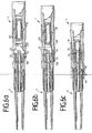
- FIG. 6 (a) - (c) show schematically different times during a plugging process.
- Fig. 6 (a) shows the beginning of the plugging process.
- the leaf spring 141 is unloaded at this time and covers the sleeve opening 121 from.
- the leaf spring 141 is formed with a curvature which is tangential to the side surface 136 at one end.
- the ferrule 23 of the connector 2 is highly precise and therefore very sensitive. Due to the plugging process, for this reason and due to a risk of contamination, for example due to metal abrasion, there may be no contact of the ferrule 23 with the leaf spring 141.
- the curvature of the leaf spring 141 is thus adapted according to the geometry of the connector 2.
- FIG. 6 (b) shows the displacement of the leaf spring 141 by a wider end face 24 of the connector 2. In this case, a sufficient distance of the ferrule 23 to the leaf spring 141 is ensured. A laser beam exit from the clutch housing 10 in the axial direction due to the release of the sleeve opening 121 is prevented by the connector 2.
- Fig. 6 (c) shows the end of the plugging operation.
- the connector 2 is received by locking means in the coupling 1.
- the leaf spring 141 is displaced by the connector 2 in the recess of the housing wall. Due to the very thin design of the leaf spring 141 is a good Anschmiegung given in the recess of the housing wall.
- the attachment of the cover 14 for protection against escaping Laser radiation therefore requires neither a change given connector 2 or an enlargement of the coupling housing 10th
- the protective device described only provides protection against leakage of harmful laser radiation. A given by this device protection against entry of dust and other impurities in the sleeve 12 is not sufficient in most cases. For additional dust protection when the connector 2 is pulled, for example, a dust cap is used.
Landscapes
- Physics & Mathematics (AREA)
- General Physics & Mathematics (AREA)
- Optics & Photonics (AREA)
- Mechanical Coupling Of Light Guides (AREA)
- Endoscopes (AREA)
- Connector Housings Or Holding Contact Members (AREA)
- Optical Couplings Of Light Guides (AREA)
- Details Of Connecting Devices For Male And Female Coupling (AREA)
Applications Claiming Priority (3)
| Application Number | Priority Date | Filing Date | Title |
|---|---|---|---|
| DE10219892 | 2002-05-03 | ||
| DE10219892A DE10219892A1 (de) | 2002-05-03 | 2002-05-03 | Kupplung für Glasfaserverbinder |
| PCT/EP2003/004293 WO2003093889A1 (de) | 2002-05-03 | 2003-04-25 | Kupplung für glasfaserverbinder mit nachrüstbarer sicherheitsklappe |
Publications (2)
| Publication Number | Publication Date |
|---|---|
| EP1502143A1 EP1502143A1 (de) | 2005-02-02 |
| EP1502143B1 true EP1502143B1 (de) | 2006-08-30 |
Family
ID=29285085
Family Applications (1)
| Application Number | Title | Priority Date | Filing Date |
|---|---|---|---|
| EP03747356A Expired - Lifetime EP1502143B1 (de) | 2002-05-03 | 2003-04-25 | Kupplung für glasfaserverbinder mit nachrüstbarer sicherheitsklappe |
Country Status (13)
| Country | Link |
|---|---|
| US (2) | US7470068B2 (da) |
| EP (1) | EP1502143B1 (da) |
| KR (1) | KR20040104699A (da) |
| CN (1) | CN100397126C (da) |
| AT (1) | ATE338287T1 (da) |
| AU (1) | AU2003232509A1 (da) |
| DE (2) | DE10219892A1 (da) |
| DK (1) | DK1502143T3 (da) |
| ES (1) | ES2271625T3 (da) |
| PL (1) | PL371590A1 (da) |
| PT (1) | PT1502143E (da) |
| RU (1) | RU2318227C2 (da) |
| WO (1) | WO2003093889A1 (da) |
Families Citing this family (59)
| Publication number | Priority date | Publication date | Assignee | Title |
|---|---|---|---|---|
| US5883995A (en) | 1997-05-20 | 1999-03-16 | Adc Telecommunications, Inc. | Fiber connector and adapter |
| US6885798B2 (en) | 2003-09-08 | 2005-04-26 | Adc Telecommunications, Inc. | Fiber optic cable and furcation module |
| TWI240095B (en) * | 2003-10-14 | 2005-09-21 | Lite On Technology Corp | Fiber optical connector |
| US7376322B2 (en) | 2004-11-03 | 2008-05-20 | Adc Telecommunications, Inc. | Fiber optic module and system including rear connectors |
| DE102005015268A1 (de) | 2005-04-04 | 2006-10-12 | Adc Gmbh | Steckverbindung |
| US7376323B2 (en) | 2005-05-25 | 2008-05-20 | Adc Telecommunications, Inc. | Fiber optic adapter module |
| US7400813B2 (en) | 2005-05-25 | 2008-07-15 | Adc Telecommunications, Inc. | Fiber optic splitter module |
| US7636507B2 (en) * | 2005-06-17 | 2009-12-22 | Adc Telecommunications, Inc. | Compact blind mateable optical splitter |
| US7346254B2 (en) | 2005-08-29 | 2008-03-18 | Adc Telecommunications, Inc. | Fiber optic splitter module with connector access |
| US7418181B2 (en) | 2006-02-13 | 2008-08-26 | Adc Telecommunications, Inc. | Fiber optic splitter module |
| US7570860B2 (en) | 2007-01-19 | 2009-08-04 | Adc Telecommunications, Inc. | Adapter panel with lateral sliding adapter arrays |
| US7570861B2 (en) | 2007-01-19 | 2009-08-04 | Adc Telecommunications, Inc. | Adapter panel with lateral sliding adapter arrays |
| US7391954B1 (en) | 2007-05-30 | 2008-06-24 | Corning Cable Systems Llc | Attenuated optical splitter module |
| US20080298748A1 (en) | 2007-05-31 | 2008-12-04 | Terry Dean Cox | Direct-connect optical splitter module |
| US20080298743A1 (en) * | 2007-05-31 | 2008-12-04 | Konstantinos Saravanos | Microsplitter module for optical connectivity |
| US8798427B2 (en) | 2007-09-05 | 2014-08-05 | Corning Cable Systems Llc | Fiber optic terminal assembly |
| US7536075B2 (en) | 2007-10-22 | 2009-05-19 | Adc Telecommunications, Inc. | Wavelength division multiplexing module |
| US7885505B2 (en) * | 2007-10-22 | 2011-02-08 | Adc Telecommunications, Inc. | Wavelength division multiplexing module |
| US8107816B2 (en) | 2008-01-29 | 2012-01-31 | Adc Telecommunications, Inc. | Wavelength division multiplexing module |
| US7903922B2 (en) * | 2008-08-07 | 2011-03-08 | Fujikura Ltd. | Optical connector holder and optical termination cabinet, and method of optical fiber wiring in optical termination cabinet |
| EP2344915A4 (en) | 2008-10-09 | 2015-01-21 | Corning Cable Sys Llc | FIBER OPTICAL CONNECTION TO ADAPTER PANEL SUPPORTING BOTH INPUT AND OUTPUT FIBERS FROM ONE OPTICAL PARTNER |
| US8879882B2 (en) | 2008-10-27 | 2014-11-04 | Corning Cable Systems Llc | Variably configurable and modular local convergence point |
| CH700064A1 (de) * | 2008-12-01 | 2010-06-15 | Reichle & De Massari Fa | Duplex-adapter und sicherungsvorrichtung für eine optische steckverbindung. |
| WO2010083369A1 (en) | 2009-01-15 | 2010-07-22 | Adc Telecommunications, Inc. | Fiber optic module, chassis and adapter |
| EP2237091A1 (en) | 2009-03-31 | 2010-10-06 | Corning Cable Systems LLC | Removably mountable fiber optic terminal |
| CN101854007B (zh) * | 2009-04-02 | 2012-08-29 | 富士康(昆山)电脑接插件有限公司 | 电连接器 |
| US8467651B2 (en) * | 2009-09-30 | 2013-06-18 | Ccs Technology Inc. | Fiber optic terminals configured to dispose a fiber optic connection panel(s) within an optical fiber perimeter and related methods |
| US8337094B2 (en) * | 2009-10-01 | 2012-12-25 | Acrolite, Inc. | Fiber optic light source adapter |
| US9547144B2 (en) | 2010-03-16 | 2017-01-17 | Corning Optical Communications LLC | Fiber optic distribution network for multiple dwelling units |
| US8727636B2 (en) * | 2010-03-19 | 2014-05-20 | Corning Incorporated | Fiber optic interface device with positionable cleaning cover |
| US8792767B2 (en) | 2010-04-16 | 2014-07-29 | Ccs Technology, Inc. | Distribution device |
| US9239442B2 (en) | 2010-04-27 | 2016-01-19 | Adc Communications (Shanghai) Co., Ltd. | Fiber optic module and chassis |
| AU2011317244A1 (en) | 2010-10-19 | 2013-05-23 | Corning Cable Systems Llc | Transition box for multiple dwelling unit fiber optic distribution network |
| US9182563B2 (en) | 2011-03-31 | 2015-11-10 | Adc Telecommunications, Inc. | Adapter plate for fiber optic module |
| US9417401B2 (en) | 2011-09-06 | 2016-08-16 | Commscope Technologies Llc | Adapter for fiber optic module |
| DE102011085840B3 (de) * | 2011-11-07 | 2013-03-28 | Trumpf Laser Gmbh + Co. Kg | Vorrichtung zum Einstellen eines Strahlprofils, Laserbearbeitungsmaschine und Verfahren zur Herstellung der Vorrichtung |
| US9219546B2 (en) | 2011-12-12 | 2015-12-22 | Corning Optical Communications LLC | Extremely high frequency (EHF) distributed antenna systems, and related components and methods |
| US10110307B2 (en) | 2012-03-02 | 2018-10-23 | Corning Optical Communications LLC | Optical network units (ONUs) for high bandwidth connectivity, and related components and methods |
| US9004778B2 (en) | 2012-06-29 | 2015-04-14 | Corning Cable Systems Llc | Indexable optical fiber connectors and optical fiber connector arrays |
| US9049500B2 (en) | 2012-08-31 | 2015-06-02 | Corning Cable Systems Llc | Fiber optic terminals, systems, and methods for network service management |
| US8909019B2 (en) | 2012-10-11 | 2014-12-09 | Ccs Technology, Inc. | System comprising a plurality of distribution devices and distribution device |
| US10031305B2 (en) | 2012-12-19 | 2018-07-24 | CommScope Connectivity Belgium BVBA | Distribution device with incrementally added splitters |
| CN105705976A (zh) | 2013-09-23 | 2016-06-22 | 泰科电子英国有限公司 | 通信底盘 |
| US9301030B2 (en) | 2013-11-11 | 2016-03-29 | Commscope Technologies Llc | Telecommunications module |
| AU2013406228B2 (en) * | 2013-11-27 | 2017-05-25 | Halliburton Energy Services, Inc. | Bottom hole assembly fiber optic shape sensing |
| CN106687841B (zh) | 2014-06-17 | 2020-08-14 | 康普连通比利时私人有限公司 | 线缆配线系统 |
| WO2015200321A1 (en) | 2014-06-23 | 2015-12-30 | Adc Telecommunications, Inc. | Fiber cable fan-out assembly and method |
| US10054753B2 (en) | 2014-10-27 | 2018-08-21 | Commscope Technologies Llc | Fiber optic cable with flexible conduit |
| FR3034208B1 (fr) * | 2015-03-24 | 2017-03-24 | Folan | Connecteur de fibre optique |
| AU2015207954C1 (en) | 2015-07-31 | 2022-05-05 | Adc Communications (Australia) Pty Limited | Cable breakout assembly |
| EP3338125A4 (en) | 2015-08-21 | 2019-04-17 | Commscope Technologies LLC | TELECOMMUNICATIONS MODULE |
| US10606009B2 (en) | 2015-12-01 | 2020-03-31 | CommScope Connectivity Belgium BVBA | Cable distribution system with fan out devices |
| WO2017129815A1 (en) | 2016-01-28 | 2017-08-03 | CommScope Connectivity Belgium BVBA | Modular hybrid closure |
| CN108780200B (zh) | 2016-03-18 | 2021-05-07 | 康普技术有限责任公司 | 光纤电缆扇出管道结构、部件和方法 |
| US10222571B2 (en) | 2016-04-07 | 2019-03-05 | Commscope Technologies Llc | Telecommunications module and frame |
| US10890730B2 (en) | 2016-08-31 | 2021-01-12 | Commscope Technologies Llc | Fiber optic cable clamp and clamp assembly |
| US10914909B2 (en) | 2016-10-13 | 2021-02-09 | Commscope Technologies Llc | Fiber optic breakout transition assembly incorporating epoxy plug and cable strain relief |
| EP3622336A4 (en) | 2017-05-08 | 2021-01-20 | Commscope Technologies LLC | Fiber-optic breakout transition assembly |
| US10281668B2 (en) * | 2017-07-14 | 2019-05-07 | Senko Advanced Components, Inc. | Ultra-small form factor optical connectors |
Family Cites Families (20)
| Publication number | Priority date | Publication date | Assignee | Title |
|---|---|---|---|---|
| DE2845420C2 (de) * | 1978-10-18 | 1984-11-08 | Bunker Ramo Corp., Oak Brook, Ill. | Lichtleiter-Steckverbindung |
| US4767179A (en) * | 1982-12-20 | 1988-08-30 | Molex Incorporated | Fiber optic connector assembly |
| JPH07104457B2 (ja) * | 1989-10-19 | 1995-11-13 | 日本板硝子株式会社 | 光コネクタ |
| AU660859B2 (en) | 1992-11-26 | 1995-07-06 | Diamond S.A. | Sleeve portion for an optical fibre plug connector |
| DE4303780C1 (de) | 1993-02-05 | 1994-08-04 | Siemens Ag | Elektro-optischer Modul |
| US5329604A (en) | 1993-02-11 | 1994-07-12 | International Business Machines Corporation | Optical fiber coupling device and optoelectronic system utilizing same |
| DE4330212C2 (de) | 1993-08-30 | 1996-02-08 | Edmond Graesser | Kupplungsteil zum Aufnehmen eines Steckerteils für Lichtwellenleiter |
| JPH08125615A (ja) * | 1994-10-20 | 1996-05-17 | Fujitsu Ltd | レーザ光漏洩防止装置 |
| JPH09211264A (ja) | 1996-02-01 | 1997-08-15 | Molex Inc | 光ファイバコネクタ用アダプタ |
| DE19653148A1 (de) * | 1996-12-19 | 1998-06-25 | Bayerische Motoren Werke Ag | Teleskopisch einfederbare Radführung |
| US6039585A (en) * | 1997-03-10 | 2000-03-21 | Reynolds Industries Incorporated | Connector assembly with self activating environmental seal |
| US5923805A (en) * | 1997-12-22 | 1999-07-13 | Lucent Technologies Inc. | Connector for plastic optical fiber |
| WO1999040466A1 (en) | 1998-02-05 | 1999-08-12 | Alcoa Fujikura Ltd. | Fiber optic adapter shutter door assembly |
| JP3644884B2 (ja) * | 1999-10-25 | 2005-05-11 | 古河電気工業株式会社 | 遮光シャッター付きアダプタおよび遮光シャッター付き光モジュールレセプタクル |
| US6375363B1 (en) * | 2000-06-02 | 2002-04-23 | Cisco Technology, Inc. | Multi-part optical safety clip |
| JP2002016350A (ja) | 2000-06-28 | 2002-01-18 | Canon Inc | はんだ付け方法 |
| DE10139670C2 (de) | 2000-09-26 | 2003-07-24 | Krone Gmbh | Kupplung für Glasfaserverbindung |
| JP2002116350A (ja) * | 2000-10-05 | 2002-04-19 | Hirose Electric Co Ltd | 光ケーブル用アダプタ又はレセプタクル |
| DE50105690D1 (de) | 2001-06-29 | 2005-04-28 | Diamond Sa | Buchsenteil und Steckerteil für eine optische Steckverbindung |
| US6688780B2 (en) * | 2002-02-07 | 2004-02-10 | Amphenol Corporation | Cantilevered shutter for optical adapter |
-
2002
- 2002-05-03 DE DE10219892A patent/DE10219892A1/de not_active Withdrawn
-
2003
- 2003-04-25 US US10/513,243 patent/US7470068B2/en not_active Expired - Fee Related
- 2003-04-25 WO PCT/EP2003/004293 patent/WO2003093889A1/de not_active Ceased
- 2003-04-25 CN CNB038099403A patent/CN100397126C/zh not_active Expired - Fee Related
- 2003-04-25 PL PL03371590A patent/PL371590A1/xx not_active Application Discontinuation
- 2003-04-25 PT PT03747356T patent/PT1502143E/pt unknown
- 2003-04-25 DE DE50304861T patent/DE50304861D1/de not_active Expired - Fee Related
- 2003-04-25 AU AU2003232509A patent/AU2003232509A1/en not_active Abandoned
- 2003-04-25 ES ES03747356T patent/ES2271625T3/es not_active Expired - Lifetime
- 2003-04-25 EP EP03747356A patent/EP1502143B1/de not_active Expired - Lifetime
- 2003-04-25 RU RU2004135316/28A patent/RU2318227C2/ru not_active IP Right Cessation
- 2003-04-25 AT AT03747356T patent/ATE338287T1/de not_active IP Right Cessation
- 2003-04-25 DK DK03747356T patent/DK1502143T3/da active
- 2003-04-25 KR KR10-2004-7017688A patent/KR20040104699A/ko not_active Ceased
-
2008
- 2008-11-21 US US12/276,076 patent/US7611291B2/en not_active Expired - Lifetime
Also Published As
| Publication number | Publication date |
|---|---|
| US7470068B2 (en) | 2008-12-30 |
| DE10219892A1 (de) | 2004-02-05 |
| HK1079853A1 (zh) | 2006-04-13 |
| CN1659462A (zh) | 2005-08-24 |
| CN100397126C (zh) | 2008-06-25 |
| DE50304861D1 (de) | 2006-10-12 |
| US7611291B2 (en) | 2009-11-03 |
| KR20040104699A (ko) | 2004-12-10 |
| US20090136183A1 (en) | 2009-05-28 |
| PT1502143E (pt) | 2006-12-29 |
| WO2003093889A1 (de) | 2003-11-13 |
| RU2318227C2 (ru) | 2008-02-27 |
| EP1502143A1 (de) | 2005-02-02 |
| PL371590A1 (en) | 2005-06-27 |
| ATE338287T1 (de) | 2006-09-15 |
| ES2271625T3 (es) | 2007-04-16 |
| US20060083468A1 (en) | 2006-04-20 |
| AU2003232509A1 (en) | 2003-11-17 |
| RU2004135316A (ru) | 2005-09-10 |
| DK1502143T3 (da) | 2006-12-11 |
Similar Documents
| Publication | Publication Date | Title |
|---|---|---|
| EP1502143B1 (de) | Kupplung für glasfaserverbinder mit nachrüstbarer sicherheitsklappe | |
| EP1419408B1 (de) | Universaladapter | |
| DE60221169T2 (de) | Faseroptisches Steckermodul | |
| DE102009011388B3 (de) | Steckverbinder für Lichtwellenleiter | |
| DE60038089T2 (de) | Faseroptisches Stecker-Modul | |
| DE60027847T2 (de) | Montierungssystem für eine Steckverbinderanordnung auf einem Substrat | |
| EP2104190B1 (de) | Adapter zur Aufnahme eines Steckerteiles | |
| DE69317832T2 (de) | Leiterplattenmontierter faseroptischer Stecker | |
| EP2452220A1 (de) | Steckervorrichtung für optisches kabel | |
| EP2624033A1 (de) | Sicherheitssystem für optischen Steckverbinder | |
| CH703904A2 (de) | Steckverbinder. | |
| DE19857622C2 (de) | Optische Steckverbindung | |
| EP0855046B1 (de) | Optischer steckverbinder | |
| EP1680697A1 (de) | Faseroptischer stecker sowie einfach- und doppelkupplung zur aufnahme eines derartigen steckers | |
| EP1598685A1 (de) | Einrichtung für eine optische Steckverbindung | |
| DE10146702B4 (de) | Steckverbinder mit einem Verriegelungssicherungsmechanismus | |
| EP1202093B1 (de) | Anschlussklemme für mindestens einen Lichtwellenleiter | |
| EP1674907B1 (de) | Stecker für Lichtwellenleiter | |
| EP0847541B1 (de) | Optischer steckverbinder | |
| DE102005043787B4 (de) | Kontaktierungseinrichtung | |
| DE4425821C1 (de) | Schutzsystem für einen Lichtwellenleiterstecker und eine korrespondierende ankoppelbare Kopplungsbuchse | |
| DE20317751U1 (de) | Stecker zur Herstellung einer Lichtwellenleitersteckverbindung sowie Doppelkupplung und Receptacle zur Aufnahme eines derartigen Steckers | |
| DE19934727B4 (de) | Optische Steckverbindungsvorrichtung | |
| EP0994526B1 (de) | Stecker und Klemmbuchse zum Anschluss eines Lautsprechers | |
| DE102012112746A1 (de) | Spleißvorrichtung |
Legal Events
| Date | Code | Title | Description |
|---|---|---|---|
| PUAI | Public reference made under article 153(3) epc to a published international application that has entered the european phase |
Free format text: ORIGINAL CODE: 0009012 |
|
| 17P | Request for examination filed |
Effective date: 20041101 |
|
| AK | Designated contracting states |
Kind code of ref document: A1 Designated state(s): AT BE BG CH CY CZ DE DK EE ES FI FR GB GR HU IE IT LI LU MC NL PT RO SE SI SK TR |
|
| AX | Request for extension of the european patent |
Extension state: AL LT LV MK |
|
| RAP1 | Party data changed (applicant data changed or rights of an application transferred) |
Owner name: KRONE GMBH |
|
| 17Q | First examination report despatched |
Effective date: 20050207 |
|
| DAX | Request for extension of the european patent (deleted) | ||
| RAP1 | Party data changed (applicant data changed or rights of an application transferred) |
Owner name: ADC GMBH |
|
| GRAP | Despatch of communication of intention to grant a patent |
Free format text: ORIGINAL CODE: EPIDOSNIGR1 |
|
| GRAS | Grant fee paid |
Free format text: ORIGINAL CODE: EPIDOSNIGR3 |
|
| GRAA | (expected) grant |
Free format text: ORIGINAL CODE: 0009210 |
|
| AK | Designated contracting states |
Kind code of ref document: B1 Designated state(s): AT BE BG CH CY CZ DE DK EE ES FI FR GB GR HU IE IT LI LU MC NL PT RO SE SI SK TR |
|
| PG25 | Lapsed in a contracting state [announced via postgrant information from national office to epo] |
Ref country code: IT Free format text: LAPSE BECAUSE OF FAILURE TO SUBMIT A TRANSLATION OF THE DESCRIPTION OR TO PAY THE FEE WITHIN THE PRESCRIBED TIME-LIMIT;WARNING: LAPSES OF ITALIAN PATENTS WITH EFFECTIVE DATE BEFORE 2007 MAY HAVE OCCURRED AT ANY TIME BEFORE 2007. THE CORRECT EFFECTIVE DATE MAY BE DIFFERENT FROM THE ONE RECORDED. Effective date: 20060830 Ref country code: RO Free format text: LAPSE BECAUSE OF FAILURE TO SUBMIT A TRANSLATION OF THE DESCRIPTION OR TO PAY THE FEE WITHIN THE PRESCRIBED TIME-LIMIT Effective date: 20060830 Ref country code: SI Free format text: LAPSE BECAUSE OF FAILURE TO SUBMIT A TRANSLATION OF THE DESCRIPTION OR TO PAY THE FEE WITHIN THE PRESCRIBED TIME-LIMIT Effective date: 20060830 Ref country code: SK Free format text: LAPSE BECAUSE OF FAILURE TO SUBMIT A TRANSLATION OF THE DESCRIPTION OR TO PAY THE FEE WITHIN THE PRESCRIBED TIME-LIMIT Effective date: 20060830 |
|
| REG | Reference to a national code |
Ref country code: GB Ref legal event code: FG4D Free format text: NOT ENGLISH |
|
| REG | Reference to a national code |
Ref country code: CH Ref legal event code: EP |
|
| REG | Reference to a national code |
Ref country code: IE Ref legal event code: FG4D Free format text: LANGUAGE OF EP DOCUMENT: GERMAN |
|
| REF | Corresponds to: |
Ref document number: 50304861 Country of ref document: DE Date of ref document: 20061012 Kind code of ref document: P |
|
| REG | Reference to a national code |
Ref country code: CH Ref legal event code: NV Representative=s name: MICHELI & CIE INGENIEURS-CONSEILS |
|
| REG | Reference to a national code |
Ref country code: SE Ref legal event code: TRGR |
|
| REG | Reference to a national code |
Ref country code: DK Ref legal event code: T3 |
|
| REG | Reference to a national code |
Ref country code: GR Ref legal event code: EP Ref document number: 20060404112 Country of ref document: GR |
|
| REG | Reference to a national code |
Ref country code: PT Ref legal event code: SC4A Free format text: AVAILABILITY OF NATIONAL TRANSLATION Effective date: 20061108 |
|
| REG | Reference to a national code |
Ref country code: HU Ref legal event code: AG4A Ref document number: E000907 Country of ref document: HU |
|
| ET | Fr: translation filed | ||
| REG | Reference to a national code |
Ref country code: ES Ref legal event code: FG2A Ref document number: 2271625 Country of ref document: ES Kind code of ref document: T3 |
|
| PLBE | No opposition filed within time limit |
Free format text: ORIGINAL CODE: 0009261 |
|
| STAA | Information on the status of an ep patent application or granted ep patent |
Free format text: STATUS: NO OPPOSITION FILED WITHIN TIME LIMIT |
|
| 26N | No opposition filed |
Effective date: 20070531 |
|
| PG25 | Lapsed in a contracting state [announced via postgrant information from national office to epo] |
Ref country code: EE Free format text: LAPSE BECAUSE OF FAILURE TO SUBMIT A TRANSLATION OF THE DESCRIPTION OR TO PAY THE FEE WITHIN THE PRESCRIBED TIME-LIMIT Effective date: 20060830 |
|
| PG25 | Lapsed in a contracting state [announced via postgrant information from national office to epo] |
Ref country code: MC Free format text: LAPSE BECAUSE OF NON-PAYMENT OF DUE FEES Effective date: 20070430 |
|
| PGFP | Annual fee paid to national office [announced via postgrant information from national office to epo] |
Ref country code: BG Payment date: 20090423 Year of fee payment: 7 Ref country code: DK Payment date: 20090423 Year of fee payment: 7 Ref country code: ES Payment date: 20090424 Year of fee payment: 7 Ref country code: IE Payment date: 20090430 Year of fee payment: 7 |
|
| PG25 | Lapsed in a contracting state [announced via postgrant information from national office to epo] |
Ref country code: LU Free format text: LAPSE BECAUSE OF NON-PAYMENT OF DUE FEES Effective date: 20070425 Ref country code: CY Free format text: LAPSE BECAUSE OF FAILURE TO SUBMIT A TRANSLATION OF THE DESCRIPTION OR TO PAY THE FEE WITHIN THE PRESCRIBED TIME-LIMIT Effective date: 20060830 |
|
| PGFP | Annual fee paid to national office [announced via postgrant information from national office to epo] |
Ref country code: AT Payment date: 20090423 Year of fee payment: 7 Ref country code: CZ Payment date: 20090416 Year of fee payment: 7 Ref country code: DE Payment date: 20090427 Year of fee payment: 7 Ref country code: FI Payment date: 20090427 Year of fee payment: 7 Ref country code: FR Payment date: 20090420 Year of fee payment: 7 Ref country code: IT Payment date: 20090429 Year of fee payment: 7 Ref country code: NL Payment date: 20090427 Year of fee payment: 7 Ref country code: PT Payment date: 20090422 Year of fee payment: 7 Ref country code: SE Payment date: 20090427 Year of fee payment: 7 Ref country code: TR Payment date: 20090420 Year of fee payment: 7 |
|
| PGFP | Annual fee paid to national office [announced via postgrant information from national office to epo] |
Ref country code: BE Payment date: 20090429 Year of fee payment: 7 |
|
| PGFP | Annual fee paid to national office [announced via postgrant information from national office to epo] |
Ref country code: CH Payment date: 20090427 Year of fee payment: 7 |
|
| PGFP | Annual fee paid to national office [announced via postgrant information from national office to epo] |
Ref country code: GB Payment date: 20090424 Year of fee payment: 7 Ref country code: GR Payment date: 20090428 Year of fee payment: 7 Ref country code: HU Payment date: 20090427 Year of fee payment: 7 |
|
| BERE | Be: lapsed |
Owner name: *ADC G.M.B.H. Effective date: 20100430 |
|
| REG | Reference to a national code |
Ref country code: PT Ref legal event code: MM4A Free format text: LAPSE DUE TO NON-PAYMENT OF FEES Effective date: 20101025 |
|
| REG | Reference to a national code |
Ref country code: NL Ref legal event code: V1 Effective date: 20101101 |
|
| EUG | Se: european patent has lapsed | ||
| REG | Reference to a national code |
Ref country code: CH Ref legal event code: PL |
|
| REG | Reference to a national code |
Ref country code: DK Ref legal event code: EBP |
|
| GBPC | Gb: european patent ceased through non-payment of renewal fee |
Effective date: 20100425 |
|
| REG | Reference to a national code |
Ref country code: FR Ref legal event code: ST Effective date: 20101230 |
|
| PG25 | Lapsed in a contracting state [announced via postgrant information from national office to epo] |
Ref country code: AT Free format text: LAPSE BECAUSE OF NON-PAYMENT OF DUE FEES Effective date: 20100425 Ref country code: FI Free format text: LAPSE BECAUSE OF NON-PAYMENT OF DUE FEES Effective date: 20100425 Ref country code: NL Free format text: LAPSE BECAUSE OF NON-PAYMENT OF DUE FEES Effective date: 20101101 Ref country code: IE Free format text: LAPSE BECAUSE OF NON-PAYMENT OF DUE FEES Effective date: 20100426 |
|
| PG25 | Lapsed in a contracting state [announced via postgrant information from national office to epo] |
Ref country code: PT Free format text: LAPSE BECAUSE OF NON-PAYMENT OF DUE FEES Effective date: 20101025 Ref country code: DE Free format text: LAPSE BECAUSE OF NON-PAYMENT OF DUE FEES Effective date: 20101103 Ref country code: CZ Free format text: LAPSE BECAUSE OF NON-PAYMENT OF DUE FEES Effective date: 20100425 Ref country code: CH Free format text: LAPSE BECAUSE OF NON-PAYMENT OF DUE FEES Effective date: 20100430 Ref country code: BG Free format text: LAPSE BECAUSE OF NON-PAYMENT OF DUE FEES Effective date: 20101130 Ref country code: HU Free format text: LAPSE BECAUSE OF NON-PAYMENT OF DUE FEES Effective date: 20100426 Ref country code: LI Free format text: LAPSE BECAUSE OF NON-PAYMENT OF DUE FEES Effective date: 20100430 |
|
| PG25 | Lapsed in a contracting state [announced via postgrant information from national office to epo] |
Ref country code: IT Free format text: LAPSE BECAUSE OF NON-PAYMENT OF DUE FEES Effective date: 20100425 Ref country code: BE Free format text: LAPSE BECAUSE OF NON-PAYMENT OF DUE FEES Effective date: 20100430 Ref country code: GR Free format text: LAPSE BECAUSE OF NON-PAYMENT OF DUE FEES Effective date: 20101103 Ref country code: GB Free format text: LAPSE BECAUSE OF NON-PAYMENT OF DUE FEES Effective date: 20100425 |
|
| PG25 | Lapsed in a contracting state [announced via postgrant information from national office to epo] |
Ref country code: DK Free format text: LAPSE BECAUSE OF NON-PAYMENT OF DUE FEES Effective date: 20100503 |
|
| REG | Reference to a national code |
Ref country code: ES Ref legal event code: FD2A Effective date: 20110712 |
|
| PG25 | Lapsed in a contracting state [announced via postgrant information from national office to epo] |
Ref country code: ES Free format text: LAPSE BECAUSE OF NON-PAYMENT OF DUE FEES Effective date: 20110630 |
|
| PG25 | Lapsed in a contracting state [announced via postgrant information from national office to epo] |
Ref country code: ES Free format text: LAPSE BECAUSE OF NON-PAYMENT OF DUE FEES Effective date: 20100426 |
|
| PG25 | Lapsed in a contracting state [announced via postgrant information from national office to epo] |
Ref country code: FR Free format text: LAPSE BECAUSE OF NON-PAYMENT OF DUE FEES Effective date: 20100430 |
|
| PG25 | Lapsed in a contracting state [announced via postgrant information from national office to epo] |
Ref country code: SE Free format text: LAPSE BECAUSE OF NON-PAYMENT OF DUE FEES Effective date: 20100426 |
|
| PG25 | Lapsed in a contracting state [announced via postgrant information from national office to epo] |
Ref country code: TR Free format text: LAPSE BECAUSE OF NON-PAYMENT OF DUE FEES Effective date: 20100425 |