EP1502560A2 - Intraokulare Linse zur Befestigung an der Iris - Google Patents
Intraokulare Linse zur Befestigung an der Iris Download PDFInfo
- Publication number
- EP1502560A2 EP1502560A2 EP04077622A EP04077622A EP1502560A2 EP 1502560 A2 EP1502560 A2 EP 1502560A2 EP 04077622 A EP04077622 A EP 04077622A EP 04077622 A EP04077622 A EP 04077622A EP 1502560 A2 EP1502560 A2 EP 1502560A2
- Authority
- EP
- European Patent Office
- Prior art keywords
- iris
- distal end
- forceps
- loop
- intraocular lens
- Prior art date
- Legal status (The legal status is an assumption and is not a legal conclusion. Google has not performed a legal analysis and makes no representation as to the accuracy of the status listed.)
- Granted
Links
Images







Classifications
-
- A—HUMAN NECESSITIES
- A61—MEDICAL OR VETERINARY SCIENCE; HYGIENE
- A61F—FILTERS IMPLANTABLE INTO BLOOD VESSELS; PROSTHESES; DEVICES PROVIDING PATENCY TO, OR PREVENTING COLLAPSING OF, TUBULAR STRUCTURES OF THE BODY, e.g. STENTS; ORTHOPAEDIC, NURSING OR CONTRACEPTIVE DEVICES; FOMENTATION; TREATMENT OR PROTECTION OF EYES OR EARS; BANDAGES, DRESSINGS OR ABSORBENT PADS; FIRST-AID KITS
- A61F2/00—Filters implantable into blood vessels; Prostheses, i.e. artificial substitutes or replacements for parts of the body; Appliances for connecting them with the body; Devices providing patency to, or preventing collapsing of, tubular structures of the body, e.g. stents
- A61F2/02—Prostheses implantable into the body
- A61F2/14—Eye parts, e.g. lenses or corneal implants; Artificial eyes
- A61F2/16—Intraocular lenses
- A61F2/1602—Corrective lenses for use in addition to the natural lenses of the eyes or for pseudo-phakic eyes
-
- A—HUMAN NECESSITIES
- A61—MEDICAL OR VETERINARY SCIENCE; HYGIENE
- A61F—FILTERS IMPLANTABLE INTO BLOOD VESSELS; PROSTHESES; DEVICES PROVIDING PATENCY TO, OR PREVENTING COLLAPSING OF, TUBULAR STRUCTURES OF THE BODY, e.g. STENTS; ORTHOPAEDIC, NURSING OR CONTRACEPTIVE DEVICES; FOMENTATION; TREATMENT OR PROTECTION OF EYES OR EARS; BANDAGES, DRESSINGS OR ABSORBENT PADS; FIRST-AID KITS
- A61F2/00—Filters implantable into blood vessels; Prostheses, i.e. artificial substitutes or replacements for parts of the body; Appliances for connecting them with the body; Devices providing patency to, or preventing collapsing of, tubular structures of the body, e.g. stents
- A61F2/02—Prostheses implantable into the body
- A61F2/14—Eye parts, e.g. lenses or corneal implants; Artificial eyes
- A61F2/16—Intraocular lenses
- A61F2/1602—Corrective lenses for use in addition to the natural lenses of the eyes or for pseudo-phakic eyes
- A61F2/1605—Anterior chamber lenses for use in addition to the natural lenses of the eyes, e.g. iris fixated, iris floating
- A61F2/1608—Iris fixated, e.g. by clamping iris tissue, by suturing to the iris
-
- A—HUMAN NECESSITIES
- A61—MEDICAL OR VETERINARY SCIENCE; HYGIENE
- A61F—FILTERS IMPLANTABLE INTO BLOOD VESSELS; PROSTHESES; DEVICES PROVIDING PATENCY TO, OR PREVENTING COLLAPSING OF, TUBULAR STRUCTURES OF THE BODY, e.g. STENTS; ORTHOPAEDIC, NURSING OR CONTRACEPTIVE DEVICES; FOMENTATION; TREATMENT OR PROTECTION OF EYES OR EARS; BANDAGES, DRESSINGS OR ABSORBENT PADS; FIRST-AID KITS
- A61F2/00—Filters implantable into blood vessels; Prostheses, i.e. artificial substitutes or replacements for parts of the body; Appliances for connecting them with the body; Devices providing patency to, or preventing collapsing of, tubular structures of the body, e.g. stents
- A61F2/02—Prostheses implantable into the body
- A61F2/14—Eye parts, e.g. lenses or corneal implants; Artificial eyes
- A61F2/16—Intraocular lenses
- A61F2/1662—Instruments for inserting intraocular lenses into the eye
- A61F2/1664—Instruments for inserting intraocular lenses into the eye for manual insertion during surgery, e.g. forceps-like instruments
-
- A—HUMAN NECESSITIES
- A61—MEDICAL OR VETERINARY SCIENCE; HYGIENE
- A61F—FILTERS IMPLANTABLE INTO BLOOD VESSELS; PROSTHESES; DEVICES PROVIDING PATENCY TO, OR PREVENTING COLLAPSING OF, TUBULAR STRUCTURES OF THE BODY, e.g. STENTS; ORTHOPAEDIC, NURSING OR CONTRACEPTIVE DEVICES; FOMENTATION; TREATMENT OR PROTECTION OF EYES OR EARS; BANDAGES, DRESSINGS OR ABSORBENT PADS; FIRST-AID KITS
- A61F9/00—Methods or devices for treatment of the eyes; Devices for putting in contact-lenses; Devices to correct squinting; Apparatus to guide the blind; Protective devices for the eyes, carried on the body or in the hand
- A61F9/007—Methods or devices for eye surgery
-
- A—HUMAN NECESSITIES
- A61—MEDICAL OR VETERINARY SCIENCE; HYGIENE
- A61F—FILTERS IMPLANTABLE INTO BLOOD VESSELS; PROSTHESES; DEVICES PROVIDING PATENCY TO, OR PREVENTING COLLAPSING OF, TUBULAR STRUCTURES OF THE BODY, e.g. STENTS; ORTHOPAEDIC, NURSING OR CONTRACEPTIVE DEVICES; FOMENTATION; TREATMENT OR PROTECTION OF EYES OR EARS; BANDAGES, DRESSINGS OR ABSORBENT PADS; FIRST-AID KITS
- A61F2/00—Filters implantable into blood vessels; Prostheses, i.e. artificial substitutes or replacements for parts of the body; Appliances for connecting them with the body; Devices providing patency to, or preventing collapsing of, tubular structures of the body, e.g. stents
- A61F2/02—Prostheses implantable into the body
- A61F2/14—Eye parts, e.g. lenses or corneal implants; Artificial eyes
- A61F2/16—Intraocular lenses
- A61F2002/1681—Intraocular lenses having supporting structure for lens, e.g. haptics
- A61F2002/1683—Intraocular lenses having supporting structure for lens, e.g. haptics having filiform haptics
-
- A—HUMAN NECESSITIES
- A61—MEDICAL OR VETERINARY SCIENCE; HYGIENE
- A61F—FILTERS IMPLANTABLE INTO BLOOD VESSELS; PROSTHESES; DEVICES PROVIDING PATENCY TO, OR PREVENTING COLLAPSING OF, TUBULAR STRUCTURES OF THE BODY, e.g. STENTS; ORTHOPAEDIC, NURSING OR CONTRACEPTIVE DEVICES; FOMENTATION; TREATMENT OR PROTECTION OF EYES OR EARS; BANDAGES, DRESSINGS OR ABSORBENT PADS; FIRST-AID KITS
- A61F2/00—Filters implantable into blood vessels; Prostheses, i.e. artificial substitutes or replacements for parts of the body; Appliances for connecting them with the body; Devices providing patency to, or preventing collapsing of, tubular structures of the body, e.g. stents
- A61F2/02—Prostheses implantable into the body
- A61F2/14—Eye parts, e.g. lenses or corneal implants; Artificial eyes
- A61F2/16—Intraocular lenses
- A61F2002/1681—Intraocular lenses having supporting structure for lens, e.g. haptics
- A61F2002/1683—Intraocular lenses having supporting structure for lens, e.g. haptics having filiform haptics
- A61F2002/1686—Securing a filiform haptic to a lens body
Definitions
- the present invention relates generally to the field of ophthalmics, more particularly to ophthalmic devices, and still more particularly to ophthalmic devices known as intraocular lenses (IOLs).
- IOLs intraocular lenses
- phakic is applied to an eye in which the natural ocular lens is still present. This is in contrast to an aphakic eye from which the natural ocular lens has for any reason been removed.
- a phakic eye is considered a dynamic or active eye because the living natural lens is subject to change over time, while an aphakic eye is considered a static eye because the natural lens has been removed.
- Vision in an eye is enabled by light from a viewed image being refracted to the retina by the cornea and the natural lens (and/or any implanted intraocular lens)located posterior of the cornea.
- cataracts One relatively common ocular problem is impaired or complete loss of vision due to the natural ocular lens becoming cloudy or opaque, a condition known as cataract.
- the formation of cataracts is typically associated with natural bodily ageing, and most individuals over the age of about 60 years suffer from cataracts at least to some extent.
- Cataracts cannot currently be cured, reversed, or even significantly arrested. Accordingly, the corrective action involves surgically removing the natural lens when impaired, the results being that a phakic eye becomes an aphakic eye.
- IOL intraocular lens
- Implantable IOLs were initially constructed from rigid polymethyl methacrylate (PMMA), a hard, biocompatable plastic material. More recently, IOLs have been constructed from a soft, elastically deformable, silicone or acrylate material that enables insertion of the IOLs through small ocular incisions.
- PMMA polymethyl methacrylate
- IOLs have been constructed from a soft, elastically deformable, silicone or acrylate material that enables insertion of the IOLs through small ocular incisions.
- IOLs in phakic eyes In addition to the implanting of IOLs in aphakic eyes to restore vision after removal of the natural lens, considerable interest has recently arisen in implanting IOLs in phakic eyes to correct myopia, hyperopia, presbyopia or astigmatism problems associated with non-cataract natural lenses.
- This implanting of corrective IOLs in phakic eyes is an often-attractive alternative to the wearing of corrective spectacles or contact lenses, which limit certain activities and even certain professions, or having performed such surgical procedures on the cornea as radial keratomy (RK) or photo-radial keratectomy (PRK), which may not be desired by many individuals for various reasons.
- the implanting of refractive IOLs in phakic eyes to correct vision problems is considered to constitute one of the remaining frontiers of vision correction.
- a replacement IOL is now typically implanted in the posterior chamber of the eye from which the natural lens has been removed.
- a corrective IOL for a phakic eye is most desirably implanted in the anterior chamber of the eye, forwardly of the intact natural lens in the posterior chamber of the eye.
- the former is called a posterior chamber IOL and the latter is called an anterior chamber IOL, and there are significant construction differences between the two types of IOLs.
- anterior chamber IOLs With regard to anterior chamber IOLs, there has been renewed interest in IOLs constructed for fixation to the iris (some of the earliest IOLs were iris fixated, anterior chamber IOLs). By fixing the optic supporting structure to the iris itself, contact with the sensitive filtration angle of the eye is avoided.
- Iris fixated IOLs are disclosed in United States patents 4,215,440 and 5,192,319 to Jan Worst. Both of such patents disclose IOLs employing one or more optic fixation members formed having a pair of pincer arms which, acting together, pinch an anterior surface region of the iris. This pinching action detachably attaches the IOL to the iris so that the IOL optic is ideally fixated in the region of the iris opening (i.e., the pupil of the eye).
- the present inventor considers that improvements to the iris fixated IOL designs disclosed in the two above-cited Worst patents are desirable and it is a principal objective of the present invention to provide such improvements, particularly in the areas of improving optic centration and enabling small incision implanting.
- an iris fixated intraocular lens which comprises an optic having an optical axis and anterior and posterior sides and at least two fixation members, and which may have an overall diameter of between about 7.5 mm and about 10 mm.
- Each of the fixation members have a proximal end region and a distal end region, the proximal end region comprising a flexible strand, preferably, a single flexible strand, fixed to an edge region of the optic so as to extend generally tangentially outwardly therefrom.
- the distal end region is formed into a loop having defined therein at least one narrow iris pincher gap.
- the at least one pincher gap is located on a line generally perpendicular to the optical axis, but may alternatively be formed at an angle to the perpendicular line.
- the at least two fixation members include first and second fixation members that are substantially identical to one another and are attached to the optic on opposite sides of the optical axis.
- the first and second fixation members are constructed separately from the optic, the intraocular lens being thereby a three-piece intraocular lens.
- the optic is constructed from an elastically deformable material, which may be a silicone material or an acrylic material.
- the at least two fixation members lie in an at least substantially common plane located posterior of the optic.
- each of the distal end loop of each of the at least two fixation members may be elongated into a curved shape, and in some embodiments of the invention, each of the distal end loop includes means dividing the loops into first and second segments; in which case, a first pincher gap is defined in the first loop segment and a second pincher gap is defined in the second loop segment.
- the loop dividing means lies generally perpendicular to the optical axis of the optic.
- the at least one pincher gap preferably has a width of between about 0.05 mm and about 0.25 mm, and preferably has a length between about 0.2 mm and about 0.5 mm.
- the pincher gap in the distal end loop of each of the first and second fixation members may be located in a region of the loop closest to said optical axis, or in a region of the loop furthest from said optical axis. In either case, the pincher gaps are spaced a preferred distance, D, between about 8.0 mm and about 9.0 mm, away from the optical axis of the optic.
- the fixation members are constructed as a flexible strand and the optic is constructed from an elastically deformable material, the resulting three-piece iris fixated IOL of the invention can be folded, rolled or otherwise deformed for insertion through a small, sutureless incision in the eye, as is highly desirable for such reasons as minimal patient trauma and the reduced possibility of surgical complications.
- the flexible strand fixation members enable accurate centration of the associated optic in the patient's eye upon fixation of the IOL to the iris.
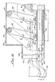
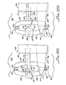
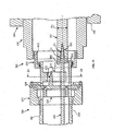
- the invention provides a combination forceps and enclavation needle instrument for use in attaching a fixation loop of an anterior chamber intraocular lens (IOL) to the anterior surface of a human ocular iris, said fixation loop having a narrow iris tissue pincher gap defined therein, said instrument comprising:
- Preferred features of the second aspect of the invention include the following:
- the invention provides a combination forceps and enclavation needle instrument for use in attaching a fixation loop of an anterior chamber intraocular lens (IOL) to the anterior surface of a human ocular iris, said fixation loop having a narrow iris tissue pincher gap defined therein, said instrument comprising:
- Preferred features of the third aspect of the invention include the following:
- Preferred features of the fourth aspect of the invention include:
- the present invention provides a hand held instrument for use in attaching a fixation loop of an anterior chamber intraocular lens (IOL) to the anterior surface of a human ocular iris, said fixation loop having a narrow iris tissue pincher gap defined therein, said instrument comprising:
- Preferred features of the fifth aspect of the invention include the following:
- the present invention provides a hand held instrument for use in attaching a fixation loop of an anterior chamber intraocular lens (IOL) to the anterior surface of a human ocular iris, said fixation loop having a narrow iris tissue pincher gap defined therein, said instrument comprising:
- FIG. 1 There is shown in FIG. 1, in vertical cross section, a forward region 10 of a representation human eye having an optical axis 11 (Axis of symmetry). Depicted in the FIG. are a cornea 12, an iris 14 and an intact, natural crystalline lens 16. A (posterior) corneal endothelium surface 18 is identified on cornea 12.
- IOL intraocular lens
- annular pupiliary spincter region 28 of iris 14 that surrounds and controls a pupil or pupiliary opening 30 having a diameter, D 1 , that typically no greater than about 8 mm for normal vision.
- annular iris collarette region 32 and an annular pupiliary dilator muscle region 34 of iris 14.
- An annular chamber angle 36 is identified at a peripheral edge region of iris 14, as is an annular trabecular meshwork 38.
- An annular ciliary processes 40 is indicated at the peripheral attachment of natural lens 16.
- iris fixated IOL 20 is fixated to iris anterior surface 24 in the general region of iris collarette 32 (the thickest region of iris 14), radially outwardly from pupillary sphincter 28.
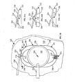
- FIGS 2 and 3 Shown in FIGS 2 and 3, comprising iris fixated IOL 20 are an optic 50 and a pair of opposing, similar and preferably identical, fixation members or haptics 52. Projecting sidewardly (radially) from opposite sides of a peripheral edge 56 of optic 50, and preferably formed in one piece with the optic, are similar structural haptic attachment abutments or bosses 58.
- Optic 50 which has respective anterior and posterior surfaces 60 and 62 (FIGS. 1 and 3), may be constructed as convex-convex (as depicted in FIG. 1), convex-concave, convex-planar, or concave-planar or concave-concave, all such and other configurations being within the scope of the present invention. Optic 50 may advantageously be provided in the diopter range between about -15 and about +15.
- optic 50 be constructed from an elastically deformable material, such as a silicone or acrylic material, enabling the optic to be folded, rolled or otherwise deformed so that IOL 20 can be implanted through an ocular incision no larger than about 3.5 mm. It is therefore preferably that the material from which optic 50 is contructed have an index of refraction of at least about 1.46 and that the optic have a diameter, D 2 , of between about 5.5 mm and about 7.0 mm (FIG. 3) and a center thickness, t 1 , no greater than about 0.8 mm (FIG. 1).
- an elastically deformable material such as a silicone or acrylic material
- Each of haptics 52 which are preferably constructed (as by micro-machining) from polymethyl methacrylate' (PMMA), is formed having an arcuate, flexible proximal end region 70 and a generally flat, loop-shaped distal end region 72.
- a proximal end 74 of each haptic 52 is fixed into an associated one of bosses 58 (FIG. 2) so that haptic proximal end region 70 extends in a direction tangential to optic edge 56.
- Such haptic-to-optic fixation can be of any type used by IOL manufacturers for the secure attachment of haptics to soft, flexible optics.
- Haptic proximal end region 70 is arcuate in plan view and arches away from optic 50 (FIG. 2). Further, proximal end region 70 is made flexible, particularly in a plane parallel to the plane of optic 50, by preferably having a width, w 1 , of about 0.25 mm and a thickness, t 2 (FIG. 3) of about 0.35 mm. Preferably portions of haptic 52 defining distal end region loop 72 have about the same thickness as set forth for haptic proximal end region 70, and may be somewhat wider, as set forth below.
- the loop into which haptic distal end region 72 is formed may be of a variety of shapes.
- the end region loop is shown in FIG. 2 as being elongated into a curved shaped having a length, l 1 and flattened into a width, w 2 .
- loop length, l 1 may be about 3.0 mm and such loop width, w 2 , may be about 1.0 mm.
- a side region 76 of distal end region loop 72 that is closest to and directly faces optic 50 is formed defining an iris pincher gap 78 (FIG. 2) having a width, w 3 , of about 0.1 mm and a length, l 2 , of about 0.4 mm.
- Iris pincher gap 78 is shown oriented in a radial direction relative to a center 80 of optic 50, but may alternatively be oriented in another direction.
- both iris pincher gaps 78 of the two haptics 52 are centered on a diameter, D 3 , which is preferably about 8.5 mm.
- Pincher gaps 78 of both haptics 52 also lie generally on a common plane 82 (FIG 3), the haptics being arched so that optic 50 is vaulted forwardly into anterior chamber 22 (FIG. 1) with posterior surface 62 anterior of plane 82 by a distance, d 1 , that is preferably about 0.5 mm.
- Overall diameter, D 4 of IOL 20 (to ends of haptics 52) is preferably between about 7.5 mm and about 10 mm so that the IOL haptics engage iris 14 at iris collarette region 32, as noted above (FIG. 1).
- optic center 80 can be easily aligned with optical axis 11 by flexing of the second haptic 52 before the second haptic is attached to the iris.
- centration of optic 50 on optical axis 11 of the eye is easily achieved.
- IOL 20 can be implanted through a small ocular incision, as is important to minimise surgical trauma and possible complications, and reduce patient recovery time, all as compared to the surgical procedure required to implant a rigid iris fixation IOL. Further in this regard, the explanting of the flexible IOL 20, in the event explanting becomes necessary as the patient's vision changes with time, is also made easier.
- FIG. 4 One of such variations is shown in FIG. 4 in connection with a variation IOL 20a, which is identical for descriptive purposes to above-described IOL 20 except as otherwise particularly described below. Corresponding elements and features are given the same reference numbers set forth above followed by an "a”.
- a looped distal end region 72a of a haptic 52a (corresponding to haptic 52) is divided radially (relative to center 80 of optic 50) by a narrow wall 90 into respective first and second loop sectors 92 and 94.
- Each such sector 92 and 94 is constructed to define an iris pincher gap 78 directly facing optic 50.
- each haptic 52a (only a representative one of which is shown) incorporates in distal end region 72a a spaced-apart pair of iris pincher gaps 78. This described doubling of the number of iris pincher gaps 78 in haptic loops 72a may sometimes be advantageous in securely detachably fixing IOL 20a to iris 14.
- FIGS. 5 and 6 Another such variation is shown in FIGS. 5 and 6 in connection with a variation iris fixation IOL 20b, which is identical for descriptive purposes to above-described IOL 20 except as otherwise particularly described below. Corresponding elements and features are given the same reference numbers set forth above followed by a "b".
- IOL 20b A principal distinction between IOL 20b and above-described IOL 20 relates to pincher gaps 78 on haptic loops 72b facing away from optic 50 instead of directly facing the optic in the case of the above-described IOL 20. Because pincher gaps 78 are spaced apart the same distance, D 3 (before disclosed in connection with IOL 20), proximal regions 70b of haptics 52b curve more closely around optic 50. Haptics 52b, are generally spaced from optic edge 56 a distance, d 2 , that is at least about equal to a closest separation distance, d 3 (FIG. 1), between anterior surface 82 of natural lens 16 and posterior surface 84 of iris 14 (a distance typically of about 0.3 mm).
- haptics 52b are otherwise similar to above-described haptics 52, this increased, C-curvature of haptics 52b may provide somewhat increased haptic flexibility. Moreover, orienting pincher gaps 78 on haptic loops 72b away from optic 50 may, in some instances, facilitate fixation of the IOL to iris 14.
- the vaulting of optic 50 relative to haptic loops 72b is preferably the same as disclosed above relative to IOL 20.
- FIG. 7 depicts another variation iris fixated IOL 20c, which is identical for descriptive purposes to above-described IOL 20b except as otherwise particularly described below. Previously described features and elements are given the same reference number followed by a "c".
- IOL 20c combines the described double pincher gap features shown for IOL 20a in FIG. 4 with IOL 20b (FIGS 5 and 6.).
- representative haptic loop 72c is vertically divided by a narrow wall 90c into first and second loop sectors 92c and 94c, respectively.
- Each sector 92c and 94c has defined a pincher gap 78 that faces away from associated optic 50.
- Pincher gaps 78 on both haptic loops 72c are spaced a distance D 3 (defined above) apart.
- FIG. 8 depicts the manner in which a representative one of pincher gaps 78, on a representative haptic distal end region loop 72 pinches up a small surface segment 98 of iris tissue into the gap, thereby releasably or detachably fixing the associated haptic (e.g., haptic 52), and hence the associated IOL (e.g.; IOL 20), to iris 14.
- the associated haptic e.g., haptic 52
- IOL e.g.; IOL 20
- This pinching up of iris segment 98 is accomplished, for example, by deflecting haptic loop regions 100 and 102 on each side of gap 78, downwardly (direction of Arrows "A") into iris surface 24. When the loop regions are released, they return to their original shape, thereby trapping iris segment 98 in gap 78.
- iris pincher gap may be made within the scope of the present invention and used in place of above-described pincher gap(s) 78.
- An example of such a variation is depicted in FIG. 9, in which a slanted iris pincher gap 78d (corresponding to above-described pincer gap 78) is depicted formed or defined in a representative haptic distal end region loop 72d (corresponding to above-described distal end region loop 72).
- Pincher gap 78d is depicted in FIG. 9 as formed or defined along a line 112 that is at an angle, ⁇ , relative to a line 114 perpendicular to end region loop 72d.
- slant angle, ⁇ is between about 30 degrees and about 60 degrees, with a slant angle of about 45 degrees being most preferred.
- Distal end region loop 72d can be detached from iris by merely rotating the end region loop back in the direction indicated by Arrow "B".
Landscapes
- Health & Medical Sciences (AREA)
- Ophthalmology & Optometry (AREA)
- Engineering & Computer Science (AREA)
- Biomedical Technology (AREA)
- Life Sciences & Earth Sciences (AREA)
- Public Health (AREA)
- Heart & Thoracic Surgery (AREA)
- Vascular Medicine (AREA)
- Veterinary Medicine (AREA)
- Animal Behavior & Ethology (AREA)
- General Health & Medical Sciences (AREA)
- Oral & Maxillofacial Surgery (AREA)
- Cardiology (AREA)
- Transplantation (AREA)
- Nuclear Medicine, Radiotherapy & Molecular Imaging (AREA)
- Surgery (AREA)
- Prostheses (AREA)
- Materials For Medical Uses (AREA)
Applications Claiming Priority (5)
| Application Number | Priority Date | Filing Date | Title |
|---|---|---|---|
| US09/312,566 US6152959A (en) | 1999-05-14 | 1999-05-14 | Iris fixated intraocular lens |
| US312566 | 1999-05-14 | ||
| US489069 | 2000-01-21 | ||
| US09/489,069 US6342058B1 (en) | 1999-05-14 | 2000-01-21 | Iris fixated intraocular lens and instrument for attaching same to an iris |
| EP00930534A EP1189555A4 (de) | 1999-05-14 | 2000-05-10 | An der iris befestigte intraokulare linse und instrument zum anbringen der linse an die iris |
Related Parent Applications (1)
| Application Number | Title | Priority Date | Filing Date |
|---|---|---|---|
| EP00930534A Division EP1189555A4 (de) | 1999-05-14 | 2000-05-10 | An der iris befestigte intraokulare linse und instrument zum anbringen der linse an die iris |
Publications (3)
| Publication Number | Publication Date |
|---|---|
| EP1502560A2 true EP1502560A2 (de) | 2005-02-02 |
| EP1502560A3 EP1502560A3 (de) | 2005-02-09 |
| EP1502560B1 EP1502560B1 (de) | 2006-07-19 |
Family
ID=32993704
Family Applications (1)
| Application Number | Title | Priority Date | Filing Date |
|---|---|---|---|
| EP20040077622 Expired - Lifetime EP1502560B1 (de) | 1999-05-14 | 2000-05-10 | Intraokulare Linse zur Befestigung an der Iris |
Country Status (6)
| Country | Link |
|---|---|
| EP (1) | EP1502560B1 (de) |
| AT (1) | ATE333252T1 (de) |
| AU (1) | AU776491B2 (de) |
| DE (1) | DE60029494T2 (de) |
| ES (1) | ES2266982T3 (de) |
| PT (1) | PT1502560E (de) |
Cited By (1)
| Publication number | Priority date | Publication date | Assignee | Title |
|---|---|---|---|---|
| CN117137679A (zh) * | 2023-10-30 | 2023-12-01 | 深圳市新产业眼科新技术有限公司 | 可治疗散光的人工晶状体 |
Family Cites Families (8)
| Publication number | Priority date | Publication date | Assignee | Title |
|---|---|---|---|---|
| US4198714A (en) * | 1977-05-06 | 1980-04-22 | Jensen Ronald P | Intraocular lens for implantation into the posterior chamber of a human eye |
| GB2085731A (en) * | 1980-10-28 | 1982-05-06 | Tennant Jerald Lee | Implant lens with biarcuate fixation |
| US4542541A (en) * | 1981-12-11 | 1985-09-24 | Pannu Jaswant S | Universal intraocular lens |
| US4666444A (en) * | 1985-09-13 | 1987-05-19 | Pannu Jaswant S | Easily insertable intraocular lens |
| US5893863A (en) * | 1989-12-05 | 1999-04-13 | Yoon; Inbae | Surgical instrument with jaws and movable internal hook member for use thereof |
| US5226908A (en) * | 1989-12-05 | 1993-07-13 | Inbae Yoon | Multi-functional instruments and stretchable ligating and occluding devices |
| US5192319A (en) * | 1991-05-20 | 1993-03-09 | Worst Jan G F | Intraocular refractive lens |
| US5584304A (en) * | 1993-11-18 | 1996-12-17 | Allergan, Inc. | Method of inserting an IOL using a forceps inside a folding tube |
-
2000
- 2000-05-10 EP EP20040077622 patent/EP1502560B1/de not_active Expired - Lifetime
- 2000-05-10 ES ES04077622T patent/ES2266982T3/es not_active Expired - Lifetime
- 2000-05-10 AT AT04077622T patent/ATE333252T1/de not_active IP Right Cessation
- 2000-05-10 PT PT04077622T patent/PT1502560E/pt unknown
- 2000-05-10 DE DE2000629494 patent/DE60029494T2/de not_active Expired - Fee Related
-
2001
- 2001-11-16 AU AU91382/01A patent/AU776491B2/en not_active Ceased
Cited By (2)
| Publication number | Priority date | Publication date | Assignee | Title |
|---|---|---|---|---|
| CN117137679A (zh) * | 2023-10-30 | 2023-12-01 | 深圳市新产业眼科新技术有限公司 | 可治疗散光的人工晶状体 |
| CN117137679B (zh) * | 2023-10-30 | 2024-03-05 | 深圳市新产业眼科新技术有限公司 | 可治疗散光的人工晶状体 |
Also Published As
| Publication number | Publication date |
|---|---|
| PT1502560E (pt) | 2006-10-31 |
| EP1502560A3 (de) | 2005-02-09 |
| AU9138201A (en) | 2002-06-06 |
| DE60029494T2 (de) | 2007-01-04 |
| EP1502560B1 (de) | 2006-07-19 |
| ES2266982T3 (es) | 2007-03-01 |
| ATE333252T1 (de) | 2006-08-15 |
| AU776491B2 (en) | 2004-09-09 |
| DE60029494D1 (de) | 2006-08-31 |
Similar Documents
| Publication | Publication Date | Title |
|---|---|---|
| US6152959A (en) | Iris fixated intraocular lens | |
| US6342058B1 (en) | Iris fixated intraocular lens and instrument for attaching same to an iris | |
| AU2003214937B2 (en) | Iris fixated intraocular lens suitable for use with attaching instrument | |
| US6755859B2 (en) | Iris fixated intraocular lenses | |
| US4494254A (en) | Intraocular lens | |
| JP4023829B2 (ja) | 自己センタリングファキック眼内レンズ | |
| EP1289452B1 (de) | Faltbare, an der iris befestigte intraokularlinse | |
| AU660688B2 (en) | Intraocular refractive lens | |
| US6537281B1 (en) | Corrective intraocular lens system, intraocular lenses, and lens handling and installation devices for use therewith | |
| US20040006387A1 (en) | Intraocular lens | |
| AU2003214937A1 (en) | Iris fixated intraocular lens suitable for use with attaching instrument | |
| MX2011005583A (es) | Dispositivos hapticos para lentes oculares. | |
| US6409763B1 (en) | Iris-supported intraocular lenses optics and rigid fixation members | |
| WO2002060346A9 (en) | Two part 'l'- or 's'-shaped phakic iol | |
| US6562070B2 (en) | Anterior chamber phakic lens | |
| CA2407629A1 (en) | Injectable iris fixated intraocular lenses | |
| AU776491B2 (en) | Iris fixated intraocular lens and instrument for attaching same to an iris |
Legal Events
| Date | Code | Title | Description |
|---|---|---|---|
| PUAI | Public reference made under article 153(3) epc to a published international application that has entered the european phase |
Free format text: ORIGINAL CODE: 0009012 |
|
| PUAL | Search report despatched |
Free format text: ORIGINAL CODE: 0009013 |
|
| 17P | Request for examination filed |
Effective date: 20040923 |
|
| AC | Divisional application: reference to earlier application |
Ref document number: 1189555 Country of ref document: EP Kind code of ref document: P |
|
| AK | Designated contracting states |
Kind code of ref document: A2 Designated state(s): AT BE CH CY DE DK ES FI FR GB GR IE IT LI LU MC NL PT SE |
|
| AK | Designated contracting states |
Kind code of ref document: A3 Designated state(s): AT BE CH CY DE DK ES FI FR GB GR IE IT LI LU MC NL PT SE |
|
| 17Q | First examination report despatched |
Effective date: 20050512 |
|
| AKX | Designation fees paid |
Designated state(s): AT BE CH CY DE DK ES FI FR GB GR IE IT LI LU MC NL PT SE |
|
| GRAP | Despatch of communication of intention to grant a patent |
Free format text: ORIGINAL CODE: EPIDOSNIGR1 |
|
| GRAS | Grant fee paid |
Free format text: ORIGINAL CODE: EPIDOSNIGR3 |
|
| GRAA | (expected) grant |
Free format text: ORIGINAL CODE: 0009210 |
|
| AC | Divisional application: reference to earlier application |
Ref document number: 1189555 Country of ref document: EP Kind code of ref document: P |
|
| AK | Designated contracting states |
Kind code of ref document: B1 Designated state(s): AT BE CH CY DE DK ES FI FR GB GR IE IT LI LU MC NL PT SE |
|
| PG25 | Lapsed in a contracting state [announced via postgrant information from national office to epo] |
Ref country code: IT Free format text: LAPSE BECAUSE OF FAILURE TO SUBMIT A TRANSLATION OF THE DESCRIPTION OR TO PAY THE FEE WITHIN THE PRESCRIBED TIME-LIMIT;WARNING: LAPSES OF ITALIAN PATENTS WITH EFFECTIVE DATE BEFORE 2007 MAY HAVE OCCURRED AT ANY TIME BEFORE 2007. THE CORRECT EFFECTIVE DATE MAY BE DIFFERENT FROM THE ONE RECORDED. Effective date: 20060719 Ref country code: FI Free format text: LAPSE BECAUSE OF FAILURE TO SUBMIT A TRANSLATION OF THE DESCRIPTION OR TO PAY THE FEE WITHIN THE PRESCRIBED TIME-LIMIT Effective date: 20060719 Ref country code: BE Free format text: LAPSE BECAUSE OF FAILURE TO SUBMIT A TRANSLATION OF THE DESCRIPTION OR TO PAY THE FEE WITHIN THE PRESCRIBED TIME-LIMIT Effective date: 20060719 Ref country code: AT Free format text: LAPSE BECAUSE OF FAILURE TO SUBMIT A TRANSLATION OF THE DESCRIPTION OR TO PAY THE FEE WITHIN THE PRESCRIBED TIME-LIMIT Effective date: 20060719 Ref country code: NL Free format text: LAPSE BECAUSE OF FAILURE TO SUBMIT A TRANSLATION OF THE DESCRIPTION OR TO PAY THE FEE WITHIN THE PRESCRIBED TIME-LIMIT Effective date: 20060719 |
|
| REG | Reference to a national code |
Ref country code: GB Ref legal event code: FG4D |
|
| REG | Reference to a national code |
Ref country code: CH Ref legal event code: EP |
|
| REG | Reference to a national code |
Ref country code: IE Ref legal event code: FG4D |
|
| REF | Corresponds to: |
Ref document number: 60029494 Country of ref document: DE Date of ref document: 20060831 Kind code of ref document: P |
|
| REG | Reference to a national code |
Ref country code: CH Ref legal event code: NV Representative=s name: TROESCH SCHEIDEGGER WERNER AG |
|
| PG25 | Lapsed in a contracting state [announced via postgrant information from national office to epo] |
Ref country code: SE Free format text: LAPSE BECAUSE OF FAILURE TO SUBMIT A TRANSLATION OF THE DESCRIPTION OR TO PAY THE FEE WITHIN THE PRESCRIBED TIME-LIMIT Effective date: 20061019 Ref country code: DK Free format text: LAPSE BECAUSE OF FAILURE TO SUBMIT A TRANSLATION OF THE DESCRIPTION OR TO PAY THE FEE WITHIN THE PRESCRIBED TIME-LIMIT Effective date: 20061019 |
|
| REG | Reference to a national code |
Ref country code: PT Ref legal event code: SC4A Effective date: 20060830 |
|
| REG | Reference to a national code |
Ref country code: GR Ref legal event code: EP Ref document number: 20060403425 Country of ref document: GR |
|
| NLV1 | Nl: lapsed or annulled due to failure to fulfill the requirements of art. 29p and 29m of the patents act | ||
| REG | Reference to a national code |
Ref country code: ES Ref legal event code: FG2A Ref document number: 2266982 Country of ref document: ES Kind code of ref document: T3 |
|
| ET | Fr: translation filed | ||
| PGFP | Annual fee paid to national office [announced via postgrant information from national office to epo] |
Ref country code: PT Payment date: 20070420 Year of fee payment: 8 |
|
| PLBE | No opposition filed within time limit |
Free format text: ORIGINAL CODE: 0009261 |
|
| STAA | Information on the status of an ep patent application or granted ep patent |
Free format text: STATUS: NO OPPOSITION FILED WITHIN TIME LIMIT |
|
| PGFP | Annual fee paid to national office [announced via postgrant information from national office to epo] |
Ref country code: CH Payment date: 20070530 Year of fee payment: 8 |
|
| 26N | No opposition filed |
Effective date: 20070420 |
|
| PG25 | Lapsed in a contracting state [announced via postgrant information from national office to epo] |
Ref country code: MC Free format text: LAPSE BECAUSE OF NON-PAYMENT OF DUE FEES Effective date: 20070531 |
|
| PG25 | Lapsed in a contracting state [announced via postgrant information from national office to epo] |
Ref country code: IE Free format text: LAPSE BECAUSE OF NON-PAYMENT OF DUE FEES Effective date: 20070510 |
|
| PGFP | Annual fee paid to national office [announced via postgrant information from national office to epo] |
Ref country code: GR Payment date: 20070531 Year of fee payment: 8 |
|
| REG | Reference to a national code |
Ref country code: PT Ref legal event code: MM4A Free format text: LAPSE DUE TO NON-PAYMENT OF FEES Effective date: 20081110 |
|
| REG | Reference to a national code |
Ref country code: CH Ref legal event code: PL |
|
| PG25 | Lapsed in a contracting state [announced via postgrant information from national office to epo] |
Ref country code: LI Free format text: LAPSE BECAUSE OF NON-PAYMENT OF DUE FEES Effective date: 20080531 Ref country code: PT Free format text: LAPSE BECAUSE OF NON-PAYMENT OF DUE FEES Effective date: 20081110 Ref country code: CH Free format text: LAPSE BECAUSE OF NON-PAYMENT OF DUE FEES Effective date: 20080531 |
|
| PG25 | Lapsed in a contracting state [announced via postgrant information from national office to epo] |
Ref country code: GR Free format text: LAPSE BECAUSE OF NON-PAYMENT OF DUE FEES Effective date: 20081204 |
|
| PGFP | Annual fee paid to national office [announced via postgrant information from national office to epo] |
Ref country code: ES Payment date: 20090526 Year of fee payment: 10 |
|
| PG25 | Lapsed in a contracting state [announced via postgrant information from national office to epo] |
Ref country code: CY Free format text: LAPSE BECAUSE OF FAILURE TO SUBMIT A TRANSLATION OF THE DESCRIPTION OR TO PAY THE FEE WITHIN THE PRESCRIBED TIME-LIMIT Effective date: 20060719 Ref country code: LU Free format text: LAPSE BECAUSE OF NON-PAYMENT OF DUE FEES Effective date: 20070510 |
|
| PGFP | Annual fee paid to national office [announced via postgrant information from national office to epo] |
Ref country code: DE Payment date: 20090528 Year of fee payment: 10 Ref country code: IT Payment date: 20090526 Year of fee payment: 10 Ref country code: FR Payment date: 20090518 Year of fee payment: 10 |
|
| PGFP | Annual fee paid to national office [announced via postgrant information from national office to epo] |
Ref country code: GB Payment date: 20090528 Year of fee payment: 10 |
|
| GBPC | Gb: european patent ceased through non-payment of renewal fee |
Effective date: 20100510 |
|
| REG | Reference to a national code |
Ref country code: FR Ref legal event code: ST Effective date: 20110131 |
|
| PG25 | Lapsed in a contracting state [announced via postgrant information from national office to epo] |
Ref country code: IT Free format text: LAPSE BECAUSE OF NON-PAYMENT OF DUE FEES Effective date: 20100510 |
|
| PG25 | Lapsed in a contracting state [announced via postgrant information from national office to epo] |
Ref country code: DE Free format text: LAPSE BECAUSE OF NON-PAYMENT OF DUE FEES Effective date: 20101201 |
|
| PG25 | Lapsed in a contracting state [announced via postgrant information from national office to epo] |
Ref country code: FR Free format text: LAPSE BECAUSE OF NON-PAYMENT OF DUE FEES Effective date: 20100531 |
|
| REG | Reference to a national code |
Ref country code: ES Ref legal event code: FD2A Effective date: 20110714 |
|
| PG25 | Lapsed in a contracting state [announced via postgrant information from national office to epo] |
Ref country code: GB Free format text: LAPSE BECAUSE OF NON-PAYMENT OF DUE FEES Effective date: 20100510 Ref country code: ES Free format text: LAPSE BECAUSE OF NON-PAYMENT OF DUE FEES Effective date: 20110704 |
|
| PG25 | Lapsed in a contracting state [announced via postgrant information from national office to epo] |
Ref country code: ES Free format text: LAPSE BECAUSE OF NON-PAYMENT OF DUE FEES Effective date: 20100511 |