EP1502654A2 - Verfahren und Vorrichtung zur Erzeugung von Tröpfchen aus einer kohärenten Flüssigkeits- oder Schmelzeschicht von gleichmässiger Dicke auf einer rotierenden Scheibe - Google Patents
Verfahren und Vorrichtung zur Erzeugung von Tröpfchen aus einer kohärenten Flüssigkeits- oder Schmelzeschicht von gleichmässiger Dicke auf einer rotierenden Scheibe Download PDFInfo
- Publication number
- EP1502654A2 EP1502654A2 EP04025910A EP04025910A EP1502654A2 EP 1502654 A2 EP1502654 A2 EP 1502654A2 EP 04025910 A EP04025910 A EP 04025910A EP 04025910 A EP04025910 A EP 04025910A EP 1502654 A2 EP1502654 A2 EP 1502654A2
- Authority
- EP
- European Patent Office
- Prior art keywords
- disk
- liquid
- melt
- droplets
- distribution means
- Prior art date
- Legal status (The legal status is an assumption and is not a legal conclusion. Google has not performed a legal analysis and makes no representation as to the accuracy of the status listed.)
- Granted
Links
Images

Classifications
-
- B—PERFORMING OPERATIONS; TRANSPORTING
- B01—PHYSICAL OR CHEMICAL PROCESSES OR APPARATUS IN GENERAL
- B01J—CHEMICAL OR PHYSICAL PROCESSES, e.g. CATALYSIS OR COLLOID CHEMISTRY; THEIR RELEVANT APPARATUS
- B01J2/00—Processes or devices for granulating materials, e.g. fertilisers in general; Rendering particulate materials free flowing in general, e.g. making them hydrophobic
- B01J2/02—Processes or devices for granulating materials, e.g. fertilisers in general; Rendering particulate materials free flowing in general, e.g. making them hydrophobic by dividing the liquid material into drops, e.g. by spraying, and solidifying the drops
-
- B—PERFORMING OPERATIONS; TRANSPORTING
- B05—SPRAYING OR ATOMISING IN GENERAL; APPLYING FLUENT MATERIALS TO SURFACES, IN GENERAL
- B05B—SPRAYING APPARATUS; ATOMISING APPARATUS; NOZZLES
- B05B3/00—Spraying or sprinkling apparatus with moving outlet elements or moving deflecting elements
- B05B3/02—Spraying or sprinkling apparatus with moving outlet elements or moving deflecting elements with rotating elements
- B05B3/10—Spraying or sprinkling apparatus with moving outlet elements or moving deflecting elements with rotating elements discharging over substantially the whole periphery of the rotating member
- B05B3/1007—Spraying or sprinkling apparatus with moving outlet elements or moving deflecting elements with rotating elements discharging over substantially the whole periphery of the rotating member characterised by the rotating member
Definitions
- the present invention refers to a method for producing droplets from a coherent layer of a liquid or melt of even thickness by means of centrifugal action along the entire periphery of a rotating disk, the liquid or melt leaving the disk as individual droplets.
- Liquid material can mechanically be finely divided into droplets (particles) in several ways. Recently, centrifugal techniques have been used for the purpose of achieving a smallest possible variation in diameter and of increasing the production capacity when droplets are formed. Originally, these types of device for droplet formation used a perforated wall in a rotating centrifuge in order to generate the actual droplets - see for example US-A-2515665. A further development of this method has been to let the manufacturing of particles take place from a rotating disk by means of a centrifugal technique. An example of this is the production of spherical particles, where droplets of liquid material by means of centrifugal action are thrown out from the disk and in a subsequent solidifying process are brought to solidify into particles.
- WO8807414 a droplet formation method and apparatus is shown, a liquid being distributed onto disks.
- a distributing means is adapted to distribute the liquid uniformly and circumferentially on the disks.
- This distributing means comprises a dosing container which is rotationally independent of the disks and from which the liquid is dosed though one or several dosing openings onto the disks. The liquid then spreads radially outwards towards cusps and is divided into particles.
- Still another problem is to obtain a layer of even thickness at the site of droplet formation at the periphery of the rapidly rotating disk.
- liquid material is supplied evenly and continuously.
- Such an even dosage is especially required when solidifying or gelling spherical particles are produced from a liquid material, for example a melt or a liquid containing suspended or dispersed particles by means of a rotating disk.
- An even and controlled supply of liquid or melt is required on the disk in order to obtain a smallest possible variation in diameter.
- melt refers to all types of substances in liquid or semiliquid form which optionally contain suspended or dispersed particles and which can be caused to solidify for example by changing the temperature, by desiccation or by chemical reactions.
- liquid refers to all materials in liquid or semiliquid form which allow droplet formation in a device as described above.
- liquid shall specifically also be considered to comprise melts as defined above.
- the feeding of liquid or melt mainly takes place according to two principles.
- the feeding takes place by means of fixed nozzles which spray the liquid directly onto a disk which is rotating at a high velocity and is provided with grooves at its peripheral edge.
- the feeding is accomplished by means of a rotating distribution means which uniformly distributes the liquid onto the disk having an angular velocity which differs from that of the distribution means. Therewith the outer disk rotates rapidly and the inner distribution means rotates slowly.
- the purpose of the invention is to produce a method and a device for controlled droplet formation, the above-mentioned problems being avoided.
- FIG 1 shows a device 10 for droplet formation or rotor which is attached to a geometrical axis 11.
- the device 10 for droplet formation comprises a distribution means 12 and a disk 13, the disk 13 first being perpendicularly screwed on the threaded axis 11 and the distribution means 12 in a corresponding way then being axially threaded on the disk 13.
- a cavity 14 is provided around the entire axis, the cavity in that way obtaining a circumferential annular aperture upwards.
- the inner wall of the cavity is provided with a conical surface 15 which can be designed in different ways.
- Spokes 16 are also substantially vertically arranged on the inner wall at equal spacing from each other. These are radially connected with the outer wall 17 of the cavity, which extends downwards and out towards the disk.
- a notch 18 in the form of a rounded edge down towards the disk 13 is circumferentially provided below the spokes along the outside of the cavity.
- the distribution means 12 and the disk 13 are circumferentially provided with a cocoperating notched deviation 21 in the form of a labyrinth which for example can be designed as opposite ring-shaped ridges and grooves in the underside of a lower projecting part of the distribution means 12 and the upper side of the disk 13 in such a way that when the distribution means and the disk are fastened a space 19 is formed between them.
- the size of this space is determined by means of a washer which is exchangeable and arranged below the distribution means 12 at the threaded part of the disk 13.
- edges 23 of the ring-shaped notched deviations which are formed in the counter sinking, are not right angled but beveled with an angle ⁇ outwards the periphery of the disk as well as inwards the axis of the device for droplet formation.
- the purpose of the notch 18 is to achieve a film which is retained on the disk, the circumferential supply of material being completely even.
- the distribution means 12 of the device 10 for droplet formation is supplied in the cavity 14 with that liquid or melt which is used for the production of particles (droplets).
- the liquid or melt is homogenous with reference to its contents and is continuously supplied by means of for example one or several stationary nozzles (not shown) while the device for droplet formation is rotated.
- the speed of rotation depends on the size of the disk 13 as well as the properties of the material supplied and preferably amounts to less than 10000 rpm.
- All surfaces which are supposed to come into contact with a liquid or melt are adapted to its properties in order to achieve an effective wetting by the liquid or melt.
- the contact surfaces of the device for droplet formation also are hydrophobic.
- the liquid or melt is transported from the conical notch 15 towards the outer wall 17 of the cavity 14.
- the conical notch on the inner wall of the cavity promotes an increased velocity and stirring of the liquid or melt, which is important especially when the liquid or melt consists of different components with different rheological properties.
- the outer wall 17 being angled outwards/downwards the liquid or melt is transported by means of the centrifugal force along the wall towards the disk 13 and past the spokes 16 which also can be aligned in such a way that the best possible adjustment of the flow is achieved during the rotation.
- the circumferentially arranged notch 18 assists in retaining an even flow of the liquid or melt during its motion from the spokes 16 down towards the upper side of the disk 13 to be spread out thereon around the entire axis of rotation.
- the liquid or melt reaches the upper side of the disk 13 around its entire periphery under the notch 18 and inwardly of the deviation notch 21 at a straight part of the space 19 at 22.
- the liquid or melt is allowed to spread outwardly towards the periphery of the disk and is during this transfer forced to pass the "arresting" notched deviation 21 with its space of equal thickness, a circumferential adjustment in the distribution of material being obtained.
- the liquid or melt After the passage through the circumferential notched deviation in the disk the liquid or melt consists of a layer of even thickness which circumferentially spreads to the periphery of the disk, from which the actual droplets are generated.
- the liquid or melt is formed into a continuous layer of even thickness by passing the same through the circumferential notched deviation.
- the function of the notched deviation is to counterbalance the variable distribution of liquid or melt fed to the disk by providing velocity changes of spreading both radially and tangentially. In this way a liquid or melt of even and continuously decreasing film thickness is obtained circumferentially, which is thus forced to be retained on the disk during its radial spreading towards the periphery of the disk without any further control and/or restriction from above.
- a layer of even thickness of liquid or melt is thus according to the invention achieved by means of the reduced influence of shear forces, viscosity changes and other dispensing properties in connection with the feeding onto the disk.
- the layer spreads radially on the rotating disk in contact with the same all the time and with a continuously decreasing thickness out towards its periphery and up to the site where droplets are formed circumferentially.
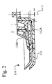
- the device for droplet formation is according to the invention constructed with several "stories". Such a construction of a second embodiment is shown in FIG 2. Also in this embodiment of the invention a device 110 for droplet formation is attached to an axis 111.
- the device 110 for droplet formation comprises distribution means 112A and 112B as well as a disk 113, the disk 113 first being perpendicularly screwed on the threaded axis 11 and successively the distribution means 112A then being axially threaded on the disk 113 and the distribution means 112B being threaded on the distribution means 112A.
- the distribution means 12 corresponds to the distribution means 112A.
- the lower projecting part of this distribution means is, however, extended in such a way that its upper side corresponds to the upper side of the disk 13.
- a further distribution means 112B is screwed on the upper part of the distribution means 112A.
- the remaining components of the device 110 for droplet formation correspond to those in FIG 1, and this embodiment of the invention thus includes for example cavities, spokes, notches, spaces, washers, and edges. Additional “stories” can in the corresponding way be arranged on a device for droplet formation according to the invention.
- the device 10 according to the invention for droplet formation being provided with a distribution means, by which the liquid or melt is supplied to the disk 13, an adjustment of the liquid or melt is achieved circumferentially. At the same time the liquid or melt is enforced a continuous and controlled spreading and change in velocity across the disk.
- This velocity can be varied in dependence of the specific application in which the liquid or melt shall be used.
- the velocity of spreading across the disk can of course be varied by changing the speed of rotation, which normally occurs when the droplet diameter is changed.
- the flow of liquid or melt, and thus its velocity of spreading across the disk, can be adjusted by changing the thickness of the washer 20.
- the distance between the distribution means 12 and the disk 13 in the notched deviation 21 - and thus the size of the space 19 also - will be changed correspondingly, a throttling of the flow of the liquid or melt being obtained.
- a distance in the notched deviation of 0.01-10 mm, preferably 0.1-2 mm, has turned out to be suitable for most applications.
- the design of the edges 23 has turned out to be of utmost importance in order to achieve a circumferentially continuous even distribution of the liquid or melt by controlling its velocity of spreading across the disk.
- the angle ⁇ of the edges should be chosen to be between 0 and 60°, preferably between 1 and 5°.
- the device for droplet formation according to the invention can be adapted to different liquids/melts in such a way that a spreading in all instances results in a film with an evenly decreasing thickness towards the periphery of the disk, droplets of minimal variation in diameter being formed.
- the film of the liquid or melt is under controlled conditions transported to a specific site, from which discrete and individual drops (particles) are formed.
- the velocity of the film across the disk is reduced in comparison with centrifugal techniques according to the state of the art, which work at corresponding angular velocities.
- the size of the droplets which can be produced by means of a device for droplet formation according to the invention can be varied within such a large interval as 1-3000 ⁇ m. However, the size normally lies within the range of 10-500 ⁇ m. A number of experiments with different liquids/melts has shown that a more uniform particle diameter is achieved with a lesser dependence on variations in feeding capacity.
- the dispersion in particle diameter is much larger when particles are produced according to the state of the art (WO8807414) than when produced according to the present invention.
- the difference in the method used is also reflected by the significantly smaller standard deviation of the inventive particles.
Landscapes
- Chemical & Material Sciences (AREA)
- Organic Chemistry (AREA)
- Chemical Kinetics & Catalysis (AREA)
- Manufacturing Of Micro-Capsules (AREA)
- Physical Or Chemical Processes And Apparatus (AREA)
- Application Of Or Painting With Fluid Materials (AREA)
- Liquid Deposition Of Substances Of Which Semiconductor Devices Are Composed (AREA)
- Processing And Handling Of Plastics And Other Materials For Molding In General (AREA)
- Extrusion Moulding Of Plastics Or The Like (AREA)
- Nozzles (AREA)
- Feeding, Discharge, Calcimining, Fusing, And Gas-Generation Devices (AREA)
Applications Claiming Priority (3)
| Application Number | Priority Date | Filing Date | Title |
|---|---|---|---|
| SE9904345A SE9904345D0 (sv) | 1999-12-01 | 1999-12-01 | method and device for producing a coherent layer of even thickness of liquid or melt on a rotating disk |
| SE9904345 | 1999-12-01 | ||
| EP00982022A EP1233833B1 (de) | 1999-12-01 | 2000-11-29 | Verfahren und vorrichtung zur erzeugung von einer, von gleichmässiger dicke, zusammenhängende flüssigkeits- oder schmelzenschicht auf einer rotierenden scheibe |
Related Parent Applications (1)
| Application Number | Title | Priority Date | Filing Date |
|---|---|---|---|
| EP00982022A Division EP1233833B1 (de) | 1999-12-01 | 2000-11-29 | Verfahren und vorrichtung zur erzeugung von einer, von gleichmässiger dicke, zusammenhängende flüssigkeits- oder schmelzenschicht auf einer rotierenden scheibe |
Publications (3)
| Publication Number | Publication Date |
|---|---|
| EP1502654A2 true EP1502654A2 (de) | 2005-02-02 |
| EP1502654A3 EP1502654A3 (de) | 2005-04-27 |
| EP1502654B1 EP1502654B1 (de) | 2009-07-01 |
Family
ID=20417914
Family Applications (2)
| Application Number | Title | Priority Date | Filing Date |
|---|---|---|---|
| EP00982022A Expired - Lifetime EP1233833B1 (de) | 1999-12-01 | 2000-11-29 | Verfahren und vorrichtung zur erzeugung von einer, von gleichmässiger dicke, zusammenhängende flüssigkeits- oder schmelzenschicht auf einer rotierenden scheibe |
| EP04025910A Expired - Lifetime EP1502654B1 (de) | 1999-12-01 | 2000-11-29 | Verfahren und Vorrichtung zur Erzeugung von Tröpfchen aus einer kohärenten Flüssigkeits- oder Schmelzeschicht von gleichmässiger Dicke auf einer rotierenden Scheibe |
Family Applications Before (1)
| Application Number | Title | Priority Date | Filing Date |
|---|---|---|---|
| EP00982022A Expired - Lifetime EP1233833B1 (de) | 1999-12-01 | 2000-11-29 | Verfahren und vorrichtung zur erzeugung von einer, von gleichmässiger dicke, zusammenhängende flüssigkeits- oder schmelzenschicht auf einer rotierenden scheibe |
Country Status (10)
| Country | Link |
|---|---|
| US (2) | US6843427B2 (de) |
| EP (2) | EP1233833B1 (de) |
| JP (1) | JP4993154B2 (de) |
| AT (2) | ATE435072T1 (de) |
| AU (1) | AU1909801A (de) |
| CA (1) | CA2394369C (de) |
| DE (2) | DE60015597T2 (de) |
| DK (1) | DK1233833T3 (de) |
| SE (1) | SE9904345D0 (de) |
| WO (1) | WO2001039890A1 (de) |
Cited By (2)
| Publication number | Priority date | Publication date | Assignee | Title |
|---|---|---|---|---|
| WO2010105329A1 (en) * | 2009-03-16 | 2010-09-23 | Gabae Techlologies, Llc | Apparatus, systems and methods for producing particles using rotating capillaries |
| WO2010105352A1 (en) * | 2009-03-16 | 2010-09-23 | Gabae Technologies, Llc | Apparatus, systems and methods for producing particles using rotating capillaries |
Families Citing this family (6)
| Publication number | Priority date | Publication date | Assignee | Title |
|---|---|---|---|---|
| SE0102369D0 (sv) * | 2001-07-03 | 2001-07-03 | Monocell Ab | New method |
| US8407083B2 (en) | 2003-09-30 | 2013-03-26 | Visa U.S.A., Inc. | Method and system for managing reward reversal after posting |
| DE102004017891B3 (de) * | 2004-04-13 | 2005-11-10 | Daimlerchrysler Ag | Glockenteller für Rotationszerstäuber von Lacken |
| JP4606065B2 (ja) * | 2004-05-24 | 2011-01-05 | トリニティ工業株式会社 | 塗装機とその回転霧化頭 |
| DE102004044595A1 (de) * | 2004-09-13 | 2006-03-30 | Basf Ag | Verfahren zur Herstellung von Verbundelementen auf der Basis von Schaumstoffen auf Isocyanatbasis |
| JP5191239B2 (ja) * | 2008-01-07 | 2013-05-08 | 旭サナック株式会社 | 噴霧装置 |
Citations (3)
| Publication number | Priority date | Publication date | Assignee | Title |
|---|---|---|---|---|
| US2515665A (en) | 1946-09-11 | 1950-07-18 | American Dyewood Company | Spray drying device |
| EP0109224A2 (de) | 1982-11-02 | 1984-05-23 | Ransburg Japan Limited | Spritzvorrichtung mit Drehglocke |
| WO1988007414A1 (en) | 1987-03-27 | 1988-10-06 | Ralf Andersson | Method and apparatus for the formation of droplets |
Family Cites Families (16)
| Publication number | Priority date | Publication date | Assignee | Title |
|---|---|---|---|---|
| US1266501A (en) * | 1915-06-14 | 1918-05-14 | Laval Separator Co De | Emulsifier. |
| US1506226A (en) * | 1919-12-08 | 1924-08-26 | Samuel M Dick | Centrifugal atomizer |
| US1870099A (en) | 1930-09-01 | 1932-08-02 | Walter B Croan | Atomizer |
| US1994239A (en) * | 1931-05-02 | 1935-03-12 | Atmospheric Nitrogen Corp | Liquid dispersing device |
| GB666341A (en) * | 1948-07-10 | 1952-02-13 | Hauser & Cie Ag Neumuehle Toes | Improved centrifugal liquid-atomiser |
| US3103311A (en) * | 1960-09-02 | 1963-09-10 | Foremost Dairies Inc | Centrifugal atomizer and method |
| JPS5445455U (de) * | 1977-09-05 | 1979-03-29 | ||
| IL55501A0 (en) * | 1977-09-14 | 1978-12-17 | Bals Edward Julius | Ratary atomiser |
| SE430370B (sv) * | 1982-07-27 | 1983-11-14 | Ingf Alf Andersson Hb | Sett och anordning for spridning och fordelning av ett partikelformigt fast eller flytande material |
| JPS60179129A (ja) * | 1984-02-24 | 1985-09-13 | Murata Mfg Co Ltd | セラミツクスラリ−の造粒乾燥装置およびその製造方法 |
| DK151198B (da) * | 1984-10-26 | 1987-11-09 | Niro Atomizer As | Forstoeverhjul til brug i et forstoevningstoerringsanlaeg |
| EP0618504B1 (de) * | 1993-03-25 | 2001-09-26 | Tokyo Electron Limited | Verfahren und Vorrichtung zur Beschichtung eines Filmes |
| US5452853A (en) * | 1994-05-04 | 1995-09-26 | Action Products Marketing Corporation | Method and apparatus for spraying grout onto the interior surface of an enclosed elongated cavity |
| JP3516358B2 (ja) * | 1994-09-08 | 2004-04-05 | 第一工業製薬株式会社 | カルボキシメチルセルロースエーテルアルカリ塩の造粒乾燥方法 |
| SE514437C2 (sv) * | 1998-09-25 | 2001-02-26 | Sandvik Ab | Sätt att spraytorka pulver för hårdmetall och liknande |
| CA2314921A1 (en) | 2000-08-03 | 2002-02-03 | Barry Partington | Apparatus and method for producing porous polymer particles |
-
1999
- 1999-12-01 SE SE9904345A patent/SE9904345D0/xx unknown
-
2000
- 2000-11-29 JP JP2001547936A patent/JP4993154B2/ja not_active Expired - Lifetime
- 2000-11-29 DE DE60015597T patent/DE60015597T2/de not_active Expired - Lifetime
- 2000-11-29 AT AT04025910T patent/ATE435072T1/de not_active IP Right Cessation
- 2000-11-29 CA CA002394369A patent/CA2394369C/en not_active Expired - Lifetime
- 2000-11-29 EP EP00982022A patent/EP1233833B1/de not_active Expired - Lifetime
- 2000-11-29 AT AT00982022T patent/ATE281244T1/de not_active IP Right Cessation
- 2000-11-29 DE DE60042502T patent/DE60042502D1/de not_active Expired - Lifetime
- 2000-11-29 DK DK00982022T patent/DK1233833T3/da active
- 2000-11-29 WO PCT/SE2000/002357 patent/WO2001039890A1/en not_active Ceased
- 2000-11-29 AU AU19098/01A patent/AU1909801A/en not_active Abandoned
- 2000-11-29 EP EP04025910A patent/EP1502654B1/de not_active Expired - Lifetime
- 2000-11-29 US US10/148,719 patent/US6843427B2/en not_active Expired - Lifetime
-
2004
- 2004-12-15 US US11/013,065 patent/US7341202B2/en not_active Expired - Lifetime
Patent Citations (4)
| Publication number | Priority date | Publication date | Assignee | Title |
|---|---|---|---|---|
| US2515665A (en) | 1946-09-11 | 1950-07-18 | American Dyewood Company | Spray drying device |
| EP0109224A2 (de) | 1982-11-02 | 1984-05-23 | Ransburg Japan Limited | Spritzvorrichtung mit Drehglocke |
| WO1988007414A1 (en) | 1987-03-27 | 1988-10-06 | Ralf Andersson | Method and apparatus for the formation of droplets |
| EP0368851A1 (de) | 1987-03-27 | 1990-05-23 | Ralf Andersson | Verfahren und vorrichtung zur bildung von tropfen. |
Cited By (3)
| Publication number | Priority date | Publication date | Assignee | Title |
|---|---|---|---|---|
| WO2010105329A1 (en) * | 2009-03-16 | 2010-09-23 | Gabae Techlologies, Llc | Apparatus, systems and methods for producing particles using rotating capillaries |
| WO2010105352A1 (en) * | 2009-03-16 | 2010-09-23 | Gabae Technologies, Llc | Apparatus, systems and methods for producing particles using rotating capillaries |
| US8597552B2 (en) | 2009-03-16 | 2013-12-03 | Evan Koslow | Apparatus, systems and methods for producing particles using rotating capillaries |
Also Published As
| Publication number | Publication date |
|---|---|
| DE60042502D1 (de) | 2009-08-13 |
| SE9904345D0 (sv) | 1999-12-01 |
| US20030029928A1 (en) | 2003-02-13 |
| AU1909801A (en) | 2001-06-12 |
| CA2394369A1 (en) | 2001-06-07 |
| EP1233833A1 (de) | 2002-08-28 |
| US20050112280A1 (en) | 2005-05-26 |
| JP2003518431A (ja) | 2003-06-10 |
| ATE281244T1 (de) | 2004-11-15 |
| WO2001039890A1 (en) | 2001-06-07 |
| EP1502654A3 (de) | 2005-04-27 |
| DE60015597D1 (de) | 2004-12-09 |
| US6843427B2 (en) | 2005-01-18 |
| EP1233833B1 (de) | 2004-11-03 |
| DE60015597T2 (de) | 2005-11-10 |
| US7341202B2 (en) | 2008-03-11 |
| EP1502654B1 (de) | 2009-07-01 |
| ATE435072T1 (de) | 2009-07-15 |
| CA2394369C (en) | 2005-07-05 |
| JP4993154B2 (ja) | 2012-08-08 |
| DK1233833T3 (da) | 2005-02-07 |
Similar Documents
| Publication | Publication Date | Title |
|---|---|---|
| KR920006865B1 (ko) | 입자나 액적을 피복하는 방법과 장치 | |
| US6338438B1 (en) | Process and a device for atomizing liquids | |
| US4407217A (en) | Distribution and treatment means | |
| US6354728B1 (en) | Device for producing a pourable product with a guide vane therein | |
| EP0185046B1 (de) | Verfahren zur einkapselung von teilchen oder von tropfen | |
| US3986706A (en) | Mixing method | |
| DK170712B1 (da) | Fremgangsmåde og apparat til opdeling af en væske i dråber | |
| EP1233833B1 (de) | Verfahren und vorrichtung zur erzeugung von einer, von gleichmässiger dicke, zusammenhängende flüssigkeits- oder schmelzenschicht auf einer rotierenden scheibe | |
| US3346192A (en) | Atomizing apparatus | |
| US3250473A (en) | Atomizing method and apparatus | |
| JPS61111161A (ja) | 噴霧輪 | |
| JPH02115032A (ja) | 粉体と液体とを混合する方法及び装置 | |
| DE60133191T2 (de) | Zerstäubungsvorrichtung für einen beschichtungsapparat | |
| JPH05285361A (ja) | 粉末状態における固体粒子を室温にて固体又は高粘度の材料により被覆する方法 | |
| JPS61230730A (ja) | 粉粒体処理装置 | |
| Hilborn | Monodisperse spherical polymer particles prepared by atomization | |
| JPS61164635A (ja) | 造粒並びにコ−テイング装置 |
Legal Events
| Date | Code | Title | Description |
|---|---|---|---|
| PUAI | Public reference made under article 153(3) epc to a published international application that has entered the european phase |
Free format text: ORIGINAL CODE: 0009012 |
|
| 17P | Request for examination filed |
Effective date: 20041102 |
|
| AC | Divisional application: reference to earlier application |
Ref document number: 1233833 Country of ref document: EP Kind code of ref document: P |
|
| AK | Designated contracting states |
Kind code of ref document: A2 Designated state(s): AT BE CH CY DE DK ES FI FR GB GR IE IT LI LU MC NL PT SE TR |
|
| PUAL | Search report despatched |
Free format text: ORIGINAL CODE: 0009013 |
|
| AK | Designated contracting states |
Kind code of ref document: A3 Designated state(s): AT BE CH CY DE DK ES FI FR GB GR IE IT LI LU MC NL PT SE TR |
|
| AKX | Designation fees paid |
Designated state(s): AT BE CH CY DE DK ES FI FR GB GR IE IT LI LU MC NL PT SE TR |
|
| RAP1 | Party data changed (applicant data changed or rights of an application transferred) |
Owner name: GE HEALTHCARE BIO-SCIENCES AB |
|
| GRAP | Despatch of communication of intention to grant a patent |
Free format text: ORIGINAL CODE: EPIDOSNIGR1 |
|
| GRAS | Grant fee paid |
Free format text: ORIGINAL CODE: EPIDOSNIGR3 |
|
| GRAA | (expected) grant |
Free format text: ORIGINAL CODE: 0009210 |
|
| AC | Divisional application: reference to earlier application |
Ref document number: 1233833 Country of ref document: EP Kind code of ref document: P |
|
| AK | Designated contracting states |
Kind code of ref document: B1 Designated state(s): AT BE CH CY DE DK ES FI FR GB GR IE IT LI LU MC NL PT SE TR |
|
| REG | Reference to a national code |
Ref country code: GB Ref legal event code: FG4D |
|
| REG | Reference to a national code |
Ref country code: CH Ref legal event code: EP |
|
| REG | Reference to a national code |
Ref country code: IE Ref legal event code: FG4D |
|
| REF | Corresponds to: |
Ref document number: 60042502 Country of ref document: DE Date of ref document: 20090813 Kind code of ref document: P |
|
| REG | Reference to a national code |
Ref country code: SE Ref legal event code: TRGR |
|
| NLV1 | Nl: lapsed or annulled due to failure to fulfill the requirements of art. 29p and 29m of the patents act | ||
| PG25 | Lapsed in a contracting state [announced via postgrant information from national office to epo] |
Ref country code: AT Free format text: LAPSE BECAUSE OF FAILURE TO SUBMIT A TRANSLATION OF THE DESCRIPTION OR TO PAY THE FEE WITHIN THE PRESCRIBED TIME-LIMIT Effective date: 20090701 Ref country code: FI Free format text: LAPSE BECAUSE OF FAILURE TO SUBMIT A TRANSLATION OF THE DESCRIPTION OR TO PAY THE FEE WITHIN THE PRESCRIBED TIME-LIMIT Effective date: 20090701 Ref country code: ES Free format text: LAPSE BECAUSE OF FAILURE TO SUBMIT A TRANSLATION OF THE DESCRIPTION OR TO PAY THE FEE WITHIN THE PRESCRIBED TIME-LIMIT Effective date: 20091012 |
|
| PG25 | Lapsed in a contracting state [announced via postgrant information from national office to epo] |
Ref country code: NL Free format text: LAPSE BECAUSE OF FAILURE TO SUBMIT A TRANSLATION OF THE DESCRIPTION OR TO PAY THE FEE WITHIN THE PRESCRIBED TIME-LIMIT Effective date: 20090701 |
|
| PG25 | Lapsed in a contracting state [announced via postgrant information from national office to epo] |
Ref country code: PT Free format text: LAPSE BECAUSE OF FAILURE TO SUBMIT A TRANSLATION OF THE DESCRIPTION OR TO PAY THE FEE WITHIN THE PRESCRIBED TIME-LIMIT Effective date: 20091102 |
|
| PG25 | Lapsed in a contracting state [announced via postgrant information from national office to epo] |
Ref country code: DK Free format text: LAPSE BECAUSE OF FAILURE TO SUBMIT A TRANSLATION OF THE DESCRIPTION OR TO PAY THE FEE WITHIN THE PRESCRIBED TIME-LIMIT Effective date: 20090701 |
|
| PLBE | No opposition filed within time limit |
Free format text: ORIGINAL CODE: 0009261 |
|
| STAA | Information on the status of an ep patent application or granted ep patent |
Free format text: STATUS: NO OPPOSITION FILED WITHIN TIME LIMIT |
|
| PG25 | Lapsed in a contracting state [announced via postgrant information from national office to epo] |
Ref country code: BE Free format text: LAPSE BECAUSE OF FAILURE TO SUBMIT A TRANSLATION OF THE DESCRIPTION OR TO PAY THE FEE WITHIN THE PRESCRIBED TIME-LIMIT Effective date: 20090701 |
|
| 26N | No opposition filed |
Effective date: 20100406 |
|
| PG25 | Lapsed in a contracting state [announced via postgrant information from national office to epo] |
Ref country code: MC Free format text: LAPSE BECAUSE OF NON-PAYMENT OF DUE FEES Effective date: 20091130 |
|
| REG | Reference to a national code |
Ref country code: CH Ref legal event code: PL |
|
| PG25 | Lapsed in a contracting state [announced via postgrant information from national office to epo] |
Ref country code: LI Free format text: LAPSE BECAUSE OF NON-PAYMENT OF DUE FEES Effective date: 20091130 Ref country code: IE Free format text: LAPSE BECAUSE OF NON-PAYMENT OF DUE FEES Effective date: 20091129 Ref country code: GR Free format text: LAPSE BECAUSE OF FAILURE TO SUBMIT A TRANSLATION OF THE DESCRIPTION OR TO PAY THE FEE WITHIN THE PRESCRIBED TIME-LIMIT Effective date: 20091002 Ref country code: CH Free format text: LAPSE BECAUSE OF NON-PAYMENT OF DUE FEES Effective date: 20091130 |
|
| PG25 | Lapsed in a contracting state [announced via postgrant information from national office to epo] |
Ref country code: LU Free format text: LAPSE BECAUSE OF NON-PAYMENT OF DUE FEES Effective date: 20091129 |
|
| PG25 | Lapsed in a contracting state [announced via postgrant information from national office to epo] |
Ref country code: TR Free format text: LAPSE BECAUSE OF FAILURE TO SUBMIT A TRANSLATION OF THE DESCRIPTION OR TO PAY THE FEE WITHIN THE PRESCRIBED TIME-LIMIT Effective date: 20090701 |
|
| PG25 | Lapsed in a contracting state [announced via postgrant information from national office to epo] |
Ref country code: CY Free format text: LAPSE BECAUSE OF FAILURE TO SUBMIT A TRANSLATION OF THE DESCRIPTION OR TO PAY THE FEE WITHIN THE PRESCRIBED TIME-LIMIT Effective date: 20090701 |
|
| REG | Reference to a national code |
Ref country code: DE Ref legal event code: R082 Ref document number: 60042502 Country of ref document: DE Representative=s name: J D REYNOLDS & CO., GB |
|
| REG | Reference to a national code |
Ref country code: FR Ref legal event code: PLFP Year of fee payment: 16 |
|
| REG | Reference to a national code |
Ref country code: DE Ref legal event code: R082 Ref document number: 60042502 Country of ref document: DE Representative=s name: J D REYNOLDS & CO., GB Ref country code: DE Ref legal event code: R081 Ref document number: 60042502 Country of ref document: DE Owner name: GE HEALTHCARE BIOPROCESS R&D AB, SE Free format text: FORMER OWNER: GE HEALTHCARE BIO-SCIENCES AB, UPPSALA, SE |
|
| REG | Reference to a national code |
Ref country code: FR Ref legal event code: TP Owner name: GE HEALTHCARE BIOPROCESS R&D AB, SE Effective date: 20160912 |
|
| REG | Reference to a national code |
Ref country code: GB Ref legal event code: 732E Free format text: REGISTERED BETWEEN 20160929 AND 20161004 |
|
| REG | Reference to a national code |
Ref country code: FR Ref legal event code: PLFP Year of fee payment: 17 |
|
| REG | Reference to a national code |
Ref country code: DE Ref legal event code: R082 Ref document number: 60042502 Country of ref document: DE |
|
| REG | Reference to a national code |
Ref country code: FR Ref legal event code: PLFP Year of fee payment: 18 |
|
| REG | Reference to a national code |
Ref country code: FR Ref legal event code: PLFP Year of fee payment: 19 |
|
| PGFP | Annual fee paid to national office [announced via postgrant information from national office to epo] |
Ref country code: SE Payment date: 20191025 Year of fee payment: 20 Ref country code: DE Payment date: 20191021 Year of fee payment: 20 |
|
| PGFP | Annual fee paid to national office [announced via postgrant information from national office to epo] |
Ref country code: FR Payment date: 20191022 Year of fee payment: 20 Ref country code: IT Payment date: 20191021 Year of fee payment: 20 |
|
| PGFP | Annual fee paid to national office [announced via postgrant information from national office to epo] |
Ref country code: GB Payment date: 20191022 Year of fee payment: 20 |
|
| REG | Reference to a national code |
Ref country code: DE Ref legal event code: R071 Ref document number: 60042502 Country of ref document: DE |
|
| REG | Reference to a national code |
Ref country code: GB Ref legal event code: PE20 Expiry date: 20201128 |
|
| PG25 | Lapsed in a contracting state [announced via postgrant information from national office to epo] |
Ref country code: GB Free format text: LAPSE BECAUSE OF EXPIRATION OF PROTECTION Effective date: 20201128 |