EP1502700B1 - Dispositif de mesure - Google Patents
Dispositif de mesure Download PDFInfo
- Publication number
- EP1502700B1 EP1502700B1 EP03017016A EP03017016A EP1502700B1 EP 1502700 B1 EP1502700 B1 EP 1502700B1 EP 03017016 A EP03017016 A EP 03017016A EP 03017016 A EP03017016 A EP 03017016A EP 1502700 B1 EP1502700 B1 EP 1502700B1
- Authority
- EP
- European Patent Office
- Prior art keywords
- carriage
- running surfaces
- linear
- motion guide
- measurement system
- Prior art date
- Legal status (The legal status is an assumption and is not a legal conclusion. Google has not performed a legal analysis and makes no representation as to the accuracy of the status listed.)
- Expired - Lifetime
Links
Images


Classifications
-
- G—PHYSICS
- G01—MEASURING; TESTING
- G01L—MEASURING FORCE, STRESS, TORQUE, WORK, MECHANICAL POWER, MECHANICAL EFFICIENCY, OR FLUID PRESSURE
- G01L5/00—Apparatus for, or methods of, measuring force, work, mechanical power, or torque, specially adapted for specific purposes
- G01L5/0009—Force sensors associated with a bearing
- G01L5/0019—Force sensors associated with a bearing by using strain gages, piezoelectric, piezo-resistive or other ohmic-resistance based sensors
-
- B—PERFORMING OPERATIONS; TRANSPORTING
- B23—MACHINE TOOLS; METAL-WORKING NOT OTHERWISE PROVIDED FOR
- B23Q—DETAILS, COMPONENTS, OR ACCESSORIES FOR MACHINE TOOLS, e.g. ARRANGEMENTS FOR COPYING OR CONTROLLING; MACHINE TOOLS IN GENERAL CHARACTERISED BY THE CONSTRUCTION OF PARTICULAR DETAILS OR COMPONENTS; COMBINATIONS OR ASSOCIATIONS OF METAL-WORKING MACHINES, NOT DIRECTED TO A PARTICULAR RESULT
- B23Q1/00—Members which are comprised in the general build-up of a form of machine, particularly relatively large fixed members
- B23Q1/25—Movable or adjustable work or tool supports
- B23Q1/44—Movable or adjustable work or tool supports using particular mechanisms
- B23Q1/56—Movable or adjustable work or tool supports using particular mechanisms with sliding pairs only, the sliding pairs being the first two elements of the mechanism
- B23Q1/58—Movable or adjustable work or tool supports using particular mechanisms with sliding pairs only, the sliding pairs being the first two elements of the mechanism a single sliding pair
-
- B—PERFORMING OPERATIONS; TRANSPORTING
- B23—MACHINE TOOLS; METAL-WORKING NOT OTHERWISE PROVIDED FOR
- B23Q—DETAILS, COMPONENTS, OR ACCESSORIES FOR MACHINE TOOLS, e.g. ARRANGEMENTS FOR COPYING OR CONTROLLING; MACHINE TOOLS IN GENERAL CHARACTERISED BY THE CONSTRUCTION OF PARTICULAR DETAILS OR COMPONENTS; COMBINATIONS OR ASSOCIATIONS OF METAL-WORKING MACHINES, NOT DIRECTED TO A PARTICULAR RESULT
- B23Q17/00—Arrangements for observing, indicating or measuring on machine tools
- B23Q17/22—Arrangements for observing, indicating or measuring on machine tools for indicating or measuring existing or desired position of tool or work
-
- F—MECHANICAL ENGINEERING; LIGHTING; HEATING; WEAPONS; BLASTING
- F16—ENGINEERING ELEMENTS AND UNITS; GENERAL MEASURES FOR PRODUCING AND MAINTAINING EFFECTIVE FUNCTIONING OF MACHINES OR INSTALLATIONS; THERMAL INSULATION IN GENERAL
- F16C—SHAFTS; FLEXIBLE SHAFTS; ELEMENTS OR CRANKSHAFT MECHANISMS; ROTARY BODIES OTHER THAN GEARING ELEMENTS; BEARINGS
- F16C29/00—Bearings for parts moving only linearly
- F16C29/04—Ball or roller bearings
- F16C29/06—Ball or roller bearings in which the rolling bodies circulate partly without carrying load
- F16C29/0633—Ball or roller bearings in which the rolling bodies circulate partly without carrying load with a bearing body defining a U-shaped carriage, i.e. surrounding a guide rail or track on three sides
- F16C29/0635—Ball or roller bearings in which the rolling bodies circulate partly without carrying load with a bearing body defining a U-shaped carriage, i.e. surrounding a guide rail or track on three sides whereby the return paths are provided as bores in a main body of the U-shaped carriage, e.g. the main body of the U-shaped carriage is a single part with end caps provided at each end
- F16C29/065—Ball or roller bearings in which the rolling bodies circulate partly without carrying load with a bearing body defining a U-shaped carriage, i.e. surrounding a guide rail or track on three sides whereby the return paths are provided as bores in a main body of the U-shaped carriage, e.g. the main body of the U-shaped carriage is a single part with end caps provided at each end with rollers
-
- F—MECHANICAL ENGINEERING; LIGHTING; HEATING; WEAPONS; BLASTING
- F16—ENGINEERING ELEMENTS AND UNITS; GENERAL MEASURES FOR PRODUCING AND MAINTAINING EFFECTIVE FUNCTIONING OF MACHINES OR INSTALLATIONS; THERMAL INSULATION IN GENERAL
- F16C—SHAFTS; FLEXIBLE SHAFTS; ELEMENTS OR CRANKSHAFT MECHANISMS; ROTARY BODIES OTHER THAN GEARING ELEMENTS; BEARINGS
- F16C2233/00—Monitoring condition, e.g. temperature, load, vibration
-
- F—MECHANICAL ENGINEERING; LIGHTING; HEATING; WEAPONS; BLASTING
- F16—ENGINEERING ELEMENTS AND UNITS; GENERAL MEASURES FOR PRODUCING AND MAINTAINING EFFECTIVE FUNCTIONING OF MACHINES OR INSTALLATIONS; THERMAL INSULATION IN GENERAL
- F16C—SHAFTS; FLEXIBLE SHAFTS; ELEMENTS OR CRANKSHAFT MECHANISMS; ROTARY BODIES OTHER THAN GEARING ELEMENTS; BEARINGS
- F16C2322/00—Apparatus used in shaping articles
- F16C2322/39—General buildup of machine tools, e.g. spindles, slides, actuators
Definitions
- the invention relates to a measuring system for the determination and evaluation of forces acting on linear bearings.
- Roller bearing linear guides are used in many areas of technology in which a component is to be moved relative to another component in a straight line and as far as possible without frictional losses.
- Such guides have as a guide body on a carriage or carriage, which is guided over rolling elements, such as balls, rollers or needles on a rail.
- the rolling elements circulate here in self-contained WälzSystemumrisen the car.
- the guide bodies usually have a support region, in which the rolling elements rest on a support surface of the carriage and on the rail and thereby carry the load to be moved. Due to the linear movement of the carriage, the rolling elements pass from the support zone into a first deflection channel, in which the rolling elements are transferred from the support zone into the return channel. After passing through the return channel, the rolling elements reach the support zone again via a second deflection channel.
- the rolling elements are not arranged in circulations, but exclusively in one or more rows, which run parallel to the longitudinal movement axis.
- linear motion guides are used for high-precision linear processing of, for example, workpiece and tool in machine tools.
- act on the linear motion guides static and dynamic forces of different and usually not known size. This makes it difficult to comply with the sometimes extremely high accuracy requirements imposed on linear motion guides become.
- the sum of these forces can affect the life of the linear motion guides.
- linear motion guides can be designed using quantitatively high safety factors. But this has the disadvantage that the guides are often replaced or maintained well before reaching the actually achievable life or maintenance cycles.
- a linear motion guide which has a carriage which can be moved along a rail, wherein the carriage is mounted via rolling elements on running surfaces formed on the rail for the respective rolling bodies.
- the linear motion guide comprises a flexible structure that is integrated either in the carriage or in the rail and at least with a subset of the rolling elements in such Contact is that a load acting on the carriage causes a deflection of the flexible structure.
- a piezoelectric force sensor is provided to register a force acting on the flexible structure.
- an active actuator pressure transducer
- the linear expansion of the actuator can be controlled with a displacement sensor. Furthermore, it is provided to measure with the aid of a displacement sensor, the deflection of a fixed to the carriage of the linear motion guide machine table with respect to an external reference bar.
- the invention is therefore based on the object to provide a better way to check the condition of linear motion guides.
- the object is achieved according to the invention by a measuring system which has at least one sensor attached to one of the guide bodies for carrying out measurements as a result of each measurement a measurement signal can be generated, which is dependent on a force-induced load on the guide body, and wherein the measuring system is provided with an evaluation unit, the measurement signals can be fed to a treatment.
- linear motion guides for example, in the context of laboratory tests or prototypes, the loads occurring in the region of linear motion guides of a planned machine can be determined. It can thus be considered actual loads that occur due to unforeseen and unconceived in the design of the machine circumstances. The knowledge gained from this can then be incorporated into the further development of the machine. This can lead to a suitable adaptation of the machine and / or to a modified design of the linear motion guide.
- an evaluation unit may be sufficient, which has a display device.
- the preparation of the measurement signals in this case can essentially consist of a visually perceptible representation of information about the quantity of the loads.
- the information shown may be, for example, the measurement signals themselves.
- the evaluation unit can be used to determine the quantity of the loads or variables dependent thereon.
- One possibility here is to determine amplitudes or peaks of the acting forces.
- the determination of the occurring and thus measured forces can be determined, for example, by considering the individual signals multiplied by a specific for the respective guide body constants (scaling factor).
- the constant in turn can be determined by comparison measurements with known forces.
- the measurement system may also be used to respond to damage, for example due to an indicative early or unforeseen failure of the linear motion guide, before damage occurs.
- a failure of a linear motion guide in many cases based on progressive wear. Wear in turn usually means an increase in the loads in the area of the linear motion guide.
- the machine in which the linear guide is installed be shut down in good time.
- the evaluation unit which detects in a preferred embodiment by an appropriate evaluation of the signals in real time of at least one sensor an unacceptably large load, in particular force, can send to the control of the machine a corresponding warning signal. The controller then turns off the machine.
- the loads measured in an operating interval of the linear motion guide can be used to determine a force-related total load variable of the respective operating interval and / or the total operating time of the respective guide.
- the directions of the individual loads can be taken into account in addition to the amount.
- An impermissible state can be, for example, irreversible damage or deformation of the guide with which the required guidance accuracy is no longer complied with becomes.
- Advantages can therefore already be achieved if, with a comparator of the evaluation unit, only the signals of the at least one sensor are compared with one or more threshold values. If the threshold values are exceeded, then actions can be triggered by the evaluation unit, for example the output of acoustic or other warning signals. The warning signals can then lead to individually initiated measures, such as a shutdown of the respective machine.
- force-induced material stresses are determined in a guide body, in particular in a carriage of the guide.
- the physical law is used that forces introduced into a body cause deformations (for example strains or compressions) that are measurable. From the size of the deformations can be concluded on the size of the load.
- known strain gauges can be used. This method has the advantage that the respective maximum forces including the bias of the linear motion guide can be accurately detected.
- a particularly simple and safe procedure for taking into account the prestressing forces can be to carry out an initial measurement, at the beginning of which the carriage of the linear guide is not yet arranged on the rail. If the carriage is then mounted on the rail and preloads are applied, the magnitude of the preload forces can be determined by comparing the signals before and after assembly.
- the second force measuring system is based on a measurement of force-induced movements. It uses elastic properties of the rolling partners (rolling elements, carriage and rail) of the linear motion guides. Loads on one of the guide body lead inter alia by a resilient deformation, for example, the rolling elements, to relative movements relative to the other guide body, in particular to relative movements transverse to the guide axis.
- the size of the relative movements can be determined by suitable sensor elements, for example those based on the eddy current principle. Also in this case conclusions can be drawn from the quantity of the relative movements at least on the amount of the forces.
- This measuring system also has the advantage that all bearing forces and moments can be detected with the correct sign.
- sensors for both aforementioned measuring methods can be provided.
- the advantages of both measurement methods or sensor types can be used.
- this makes it possible to at least reduce or avoid disadvantages of the individual sensor types.
- preload forces can be detected, while this is very difficult with displacement sensors.
- the data can be written into the storage means immediately after their creation.
- the measurement signals may first be subjected to preprocessing by suitable means.
- preprocessing can consist, for example, in an analog-to-digital conversion.
- a caching of the measurement results before their evaluation can be particularly advantageous if the Evaluation unit is not permanently connected to the guide body. This makes it possible, for example, to evaluate the data of several guide bodies with only one evaluation unit. In addition, so that the evaluation can be withdrawn the often very harsh operating conditions of linear motion guides.
- the data can be read in certain cycles.
- the data read out are fed to the evaluation unit which, depending on the type of application, determines specific target variables from the data.
- a target size for example, the total load size or the occurred maximum force at one or more measuring points come into question.
- the already determined target variables can also be stored in memory for further processing.
- the evaluation unit may be permanently in communication with the at least one sensor.
- the measurement data generated by the sensor can thus be transmitted to the evaluation unit for determining the target variable (s) immediately after it has been generated.
- Such an embodiment according to the invention can be used, for example, for monitoring linear guides for impermissibly high loads. The evaluation can then take place with advantage in real time.
- a particularly preferred embodiment of the invention - which, however, also has independent significance - relates to a compensation device having one of the measuring systems described above.
- This compensation device can be supplied with the measurement signals and evaluated by their evaluation. Adjusting elements of the compensation device preferably generate strokes and thereby forces that counteract the effects of the loads.
- oscillations are compensated or damped, which can be produced by machining a machine between the machining point and the linear movement guide or the guide and the machine bed. Such vibrations can in particular adversely affect surfaces of workpieces to be machined.
- actuators are suitable whose control elements have only a few microns or fractions thereof actuator travel, such as piezo actuator.
- the force can be determined, which currently acts parallel to the direction of action or direction of movement of the respective actuator.
- the force-proportional measuring voltage is amplified and fed to the actuator.
- the supply can be made in real time so that the movement of the respective control element is in-phase with the measured force.
- the oscillatory system linear motion guidance and machine
- the frequency range is limited only by the limit frequency of the measuring system, which may typically be at 5 kHz, for example.
- machine vibrations from 0 Hz to about 500 Hz, including non-harmonic vibrations, can be damped. Calculations can be made in the arithmetic units, which are usually equipped with standard control elements.
- the compensation device can also manage without control elements.
- the machine control can be provided by the measuring system information about currently acting on the linear motion guide forces and / or moments available. Depending on the magnitude and effective direction of the respective deformation occurring due to a load, the control can compensate for this deformation in the determination of the travel paths by addition or subtraction of corresponding compensation paths of the same amount.
- the linear motion guide shown in Fig. 1 is provided with a along a guide axis 1 rectilinear profiled rail 2, which has at least one tread 5, 6 by a predetermined profiling on its two longitudinal sides 3, 4 respectively. In the illustrated embodiment, a total of four treads 5, 6 are provided. An upper side 7 of the rail 2 is substantially planar.
- the in cross-section U-shaped carriage 8 may be formed as a metallic body with attached to the two end faces and each not shown end caps.
- the main body and the two end caps together form two WälzSystemumrise in the form of annularly closed channels.
- the base body on an inner side of each leg of the U-shape in each case two parallel to the guide axis 1 extending wings 10, which are each opposite to one of the running surfaces 5, 6 of the rail 2.
- the wings 10 form a support region of the carriage, in which rolling elements abut both on the support surface 10 and on the running surfaces 5, 6 of the rail 2 and thus can transfer loads from the carriage 8 to the rail 2 or vice versa.
- a respectively parallel to the support surface 10 extending recess in the body serves as a return channel 11 of the respective WälzSystemumlaufs.
- each WälzSystemumlauf that connects the respective support area with the return channel.
- the rolling elements formed in the embodiment as cylindrical rollers 12 are thus in a closed circuit and can circulate between the support region and the return channel 11 of each WälzSystemumlaufs over the deflection channels.
- the car of Fig. 1 comprises an inventive measuring system with different sensor types.
- the measuring system has a plurality of measuring points on the carriage, which are shown purely schematically in FIG. 2 and denoted by 20.
- a total of four measuring points 20 are provided, of which two are attached to one of the two parallel to the longitudinal axis of movement extending side surfaces 21, 22 in the upper outer edges of the car (Fig. 3).
- Each measuring point 20 has a strain gauge, which is provided with four resistors connected in a full bridge.
- each measuring point 20 is each fed to a preamplifier 23, which generate an analog measuring signal from each of them. These four measurement signals are then available for further processing, for example digitization by an A / D converter 24 and / or storage in suitable storage means 25 such as RAM modules.
- the A / D converter can be used to summarize the measurement signals supplied via individual analog inputs.
- the respective instantaneous measuring force is determined.
- the measuring force results principally from the sum of the instantaneous individual signals. So that the determined values also correspond to the actual absolute values of the occurring forces, the respective summation value can be multiplied by a scaling factor that is dependent on the respective type of wagon.
- the scaling factor can be determined by comparative measurements in which the magnitude and direction of the forces are known.
- FIGS. 3 and 4 show further sensors of the measuring system according to the invention.
- These relative movements of the carriage 8 are detected transversely to the guide axis of the guide and thus to the rail 2.
- are on the carriage 8 in Region of the two end faces opposite each of the four treads 5, 6 of the rail 2 each have a displacement sensor 31, 32, 33, 34, 35, 36, 37, 38 attached.
- the displacement sensors 27 detect a change in their distance to the respective opposite running surface 5, 6 of the rail 2. Distance changes can be caused by loads acting on the car. As soon as the carriage 8 is loaded with a force or moment, the rolling elements are compressed, which then changes the distance of the support surface of the carriage and the track of the rail.
- the displacement sensors 31 - 38 may, for example, be accommodated in plate-shaped measuring housings 27, 28, which are fastened to each of the two end faces of the carriage 8.
- displacement sensors of any type can be used.
- displacement sensors 31-38 are used which operate according to the eddy current method. Their operating principle is based on the different damping of the current flow through a coil, if it is located at different distances to a metallic surface.
- the sensors not shown in detail have a small copper coil, which forms an electrical resonant circuit together with a capacitor. The damping of the resonant circuit is dependent on the distance of the coil to the surface of the respective tread 5, 6 .
- the measuring range can be adapted to the respective requirements.
- Eddy current sensors are u.a. also particularly advantageous because it can detect metallic dirt on the rail or rail breakages with them. Such phenomena produce in the path signal of the respective sensor extreme uncorrelated jumps. Bearing loads due to chips or bearing destruction due to pitting or other injuries to the running surfaces can thus be easily detected on the basis of such a signal curve.
- the measuring signals are supplied to the electronic evaluation device, which may also be arranged on the carriage.
- a frequency generator it also contains an evaluation unit for the vibration amplitude per measuring point.
- the frequency generator excites the resonant circuit each having a coil and a capacitor to oscillations of a constant frequency.
- the resulting eight analog signals are supplied to a digitization by an A / D converter and subsequent storage in memory means, which may also be arranged on the carriage.
- the sensor signals can be read from the storage means and fed to the evaluation device. There, the determination of the actual loads in absolute values by means of a computer unit of the evaluation done.
- S 31-38 mean the measured values of the sensors 31, 32, 33, 34, 35, 36, 37, 38 from FIG. 4:
- F z C * ( ( S 31 + S 32 + S 33 + S 34 ) - S 35 + S 36 S 37 + S 38
- n C * L * ( ( S 31 + S 32 + S 37 + S 38 ) - S 33 + S 34 + S 35 + S 36 M
- G C * L * ( ( S 31 + S 35 + S 34 + S 38 ) - S 32 + S 36 + S 33 + S 37
- the constant C is carriage-specific and must be determined individually for each type of wagon. This can be done by measurements with force and torque loads known size, for example, in the context of the design of linear motion guides.
- the constants B and L correspond to distances of the sensors from each other, where L represents the distance of the four front sensors to the four rear sensors.
- the constant B corresponds to the distance between two opposing sensors, that is, for example, the distance of the sensor 36 bottom right to the sensor 31 top left of Fig. 4.
- the distance B of the respective career centers of the two treads 5, 6 determines to which the two sensors relate.
- the measured data is not needed immediately, it may be useful to save it in the measuring electronics after preprocessing. If the measuring electronics provided with a mains-independent power supply, such as a battery, so any wiring can be omitted. This is particularly advantageous for short-term tests in the testing of machines, since subsequent cabling in a machine that is already used in production is very expensive.
- a mains-independent power supply such as a battery
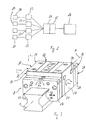
- FIGS. 5 and 6 show a compensation device according to the invention which has a measuring system according to FIGS. 2 to 4 as an integral component.
- a piezo-actuator 41 is provided between the carriage 8 and a machine frame 40 shown purely schematically.
- This is a fast response piezo actuator, as offered by the company Physik Instrumente (PI) GmbH & Co., Waldbronn, Germany, under the product name PI Piezo Actuator.
- This actuator can generate by contraction or expansion deflections A, which are in a range of ⁇ a few microns.
- the piezo actuator 41 is capable of changing the distance between the carriage surface 8a and the machine stand in proportion to the measuring force and thus compensates for the deformations of the carriage 8 and the adjacent machine parts generated by the force.
- a calculation of the control voltage or control signals of the piezoelectric actuator 41 on the basis of the measuring force takes place in an amplifier (not shown in detail in FIG. 5) of the piezoelectric positioner 41.
- these can then be controlled via analog or digital interfaces - preferably independent of the machine control.
- a force F z acting on the carriage 8 causes measurement signals of the sensors.
- the sensors of the carriage are not shown in FIG.
- the measurement signals are fed to a pre-amplifier 42 attached to the car and provided with up to 12 channels.
- the thus pre-amplified measurement signal subsequently reaches the evaluation device 26, in which the force F z is calculated. This can be done in principle in an analog or digital manner.
- the result - in the form of a further signal - the evaluation device 26 is processed by an amplifier 43 to a drive signal for the piezo-actuator 41.
- the drive signal causes a stroke movement of the piezo positioner 41 in the Z direction of a Cartesian coordinate system which is dependent on the force F z .
- Control signals for acting in other directions of space piezo positioner could be determined in principle the same way.
- vibrations of the machine stand are compensated or damped with the piezo actuator (s). Displacements of the piezoelectric positioners are used to extract energy from the vibrations of the machine measured by the measuring device and to dampen the vibrations. To optimize the damping properties of the gain and the phase angle of the drive signals is adjustable.
Landscapes
- Engineering & Computer Science (AREA)
- Mechanical Engineering (AREA)
- General Engineering & Computer Science (AREA)
- Chemical & Material Sciences (AREA)
- Analytical Chemistry (AREA)
- Physics & Mathematics (AREA)
- General Physics & Mathematics (AREA)
- Force Measurement Appropriate To Specific Purposes (AREA)
- Transition And Organic Metals Composition Catalysts For Addition Polymerization (AREA)
- Acyclic And Carbocyclic Compounds In Medicinal Compositions (AREA)
- Bearings For Parts Moving Linearly (AREA)
Claims (17)
- Système de mesure d'un guidage de déplacement linéaire, lequel guidage de déplacement linéaire présente un chariot (8) mobile le long d'un rail (2), le chariot étant logé par l'intermédiaire de corps de roulement sur plusieurs surfaces de roulement (5, 6) formées sur le rail (2) pour les différents corps de roulement,
ledit système de mesure comprenant :au moins un capteur (31 à 38) disposé sur le chariot (8) pour exécuter des mesures, avec lequel, en tant que résultat de chaque mesure, peut être généré un signal de mesure (S31, S32, S33, S34, S35, S36, S37, S38) qui dépend d'une charge conditionnée par la force (FY, FZ, MR, MN, MG) du guidage de déplacement linéaire, etun dispositif d'évaluation (26) auquel le signal de mesure peut être amené pour l'exécution d'un traitement ultérieur d'évaluation,caractérisé en ce que
le capteur correspondant est un capteur de déplacement (31 à 38) qui détecte un écart par rapport à une des surfaces de roulement (5, 6), et
le traitement ultérieur du signal de mesure comprend une détermination de la charge (FY, FZ, MR, MN, MG) en tant que fonction d'une variation de l'écart correspondant (S31, S32, S33, S34, S35, S36, S37, S38). - Système de mesure selon la revendication 1, caractérisé par plusieurs capteurs (31 à 38) disposés en des endroits différents du chariot (8), permettant chacun de déterminer des signaux de mesure (S31, S32, S33, S34, S35, S36, S37, S38) de manière essentiellement isochrone.
- Système de mesure selon la revendication 2, caractérisé en ce que, dans la zone des deux extrémités frontales du chariot (8), au moins un des capteurs (31 à 38) est disposé chaque fois vis-à-vis d'une des surfaces de roulement (5, 6).
- Système de mesure selon la revendication 3, caractérisé en ce que, dans la zone des deux extrémités frontales, quatre capteurs (31 à 38) sont disposés chaque fois vis-à-vis des surfaces de roulement (5, 6).
- Système de mesure selon la revendication 4, caractérisé en ce que la détermination de la charge comprend une détermination de forces (FY, FZ) s'exerçant sur le chariot (8) dans deux directions perpendiculaires à une direction de guidage (1) et de couples de rotation (MR, MN, MG) s'exerçant sur le chariot (8) dans trois directions.
- Système de mesure selon l'une des revendications 1 à 5, caractérisé en ce que chaque capteur (31 à 38) est logé dans un boîtier (27, 28) et le boîtier est fixé sur un côté du chariot (8).
- Système de mesure selon l'une des revendications 1 à 6, caractérisé par au moins un autre capteur (20) pour la détermination de contraintes de matériau du chariot (8).
- Système de mesure selon l'une des revendications 1 à 7, caractérisé par un dispositif d'évaluation (26) avec lequel une grandeur de charge totale conditionnée par la force peut être déterminée en incluant des mesures effectuées successivement dans le temps.
- Guidage de déplacement linéaire avec un chariot (8) mobile le long d'un rail (2), le chariot étant logé par l'intermédiaire de corps de roulement sur plusieurs surfaces de roulement (5, 6) formées sur le rail pour les différents corps de roulement, caractérisé par un système de mesure selon l'une des revendications 1 à 8.
- Guidage de déplacement linéaire selon la revendication 9, caractérisé en ce que le chariot (8) présente un corps de base à peu près en forme de U dans la section transversale, le chariot (8) étant muni d'au moins une circulation de corps de roulement dans laquelle des corps de roulement circulent d'une zone porteuse (10) dans un mouvement de retour (11).
- Procédé de détermination de l'état d'un guidage de déplacement linéaire, lequel guidage de déplacement linéaire présente un chariot (8) mobile le long d'un rail (2), le chariot étant logé par l'intermédiaire de corps de roulement sur plusieurs surfaces de roulement (5, 6) formées sur le rail (2) pour les différents corps de roulement,
caractérisé en ce que,
avec au moins un capteur de déplacement (31 à 38) fixé sur le chariot (8), un écart par rapport à une des surfaces de roulement (5, 6) est déterminé et des signaux de mesure de l'au moins un capteur de déplacement sont amenés à un dispositif d'évaluation (26) et une charge (FY, FZ, MR, MN, MG) du guidage de déplacement linéaire est déterminée à partir d'une variation de l'écart correspondant (S31, S32, S33, S34, S35, S36, S37, S38). - Procédé selon la revendication 11, dans lequel différents écarts par rapport aux surfaces de roulement (5, 6) sont mesurés avec plusieurs capteurs de déplacement (31 à 38).
- Procédé selon la revendication 12, dans lequel, dans la zone des deux extrémités frontales du chariot (8), au moins un des écarts est mesuré par rapport à une des surfaces de roulement (5, 6).
- Procédé selon la revendication 13, dans lequel, dans la zone des deux extrémités frontales, quatre écarts par rapport aux surfaces de roulement (5, 6) sont chaque fois mesurés avec quatre capteurs de déplacement (31 à 38).
- Procédé selon la revendication 14, dans lequel des variations des écarts sont déterminées et, à partir des variations, des forces (FY, FZ) s'exerçant sur le chariot dans deux directions perpendiculaires à une direction de guidage (1) et des couples de rotation (MR, MN, MG) s'exerçant sur le chariot dans trois directions sont déterminés.
- Procédé selon l'une des revendications 11 à 15, dans lequel, pendant un intervalle de fonctionnement, une charge est chaque fois mesurée à plusieurs instants successifs et une grandeur de charge totale est déterminée à partir des différentes charges.
- Procédé selon la revendication 16, dans lequel la fin de la durée de vie du guidage de déplacement linéaire et/ou l'atteinte de cycles d'entretien déterminés est obtenue par comparaison de la grandeur de charge totale avec des valeurs limites prédéterminées de manière correspondante.
Priority Applications (3)
| Application Number | Priority Date | Filing Date | Title |
|---|---|---|---|
| DE50307020T DE50307020D1 (de) | 2003-07-26 | 2003-07-26 | Messsystem |
| EP03017016A EP1502700B1 (fr) | 2003-07-26 | 2003-07-26 | Dispositif de mesure |
| AT03017016T ATE359151T1 (de) | 2003-07-26 | 2003-07-26 | Messsystem |
Applications Claiming Priority (1)
| Application Number | Priority Date | Filing Date | Title |
|---|---|---|---|
| EP03017016A EP1502700B1 (fr) | 2003-07-26 | 2003-07-26 | Dispositif de mesure |
Publications (2)
| Publication Number | Publication Date |
|---|---|
| EP1502700A1 EP1502700A1 (fr) | 2005-02-02 |
| EP1502700B1 true EP1502700B1 (fr) | 2007-04-11 |
Family
ID=33522283
Family Applications (1)
| Application Number | Title | Priority Date | Filing Date |
|---|---|---|---|
| EP03017016A Expired - Lifetime EP1502700B1 (fr) | 2003-07-26 | 2003-07-26 | Dispositif de mesure |
Country Status (3)
| Country | Link |
|---|---|
| EP (1) | EP1502700B1 (fr) |
| AT (1) | ATE359151T1 (fr) |
| DE (1) | DE50307020D1 (fr) |
Cited By (2)
| Publication number | Priority date | Publication date | Assignee | Title |
|---|---|---|---|---|
| DE102013226201A1 (de) | 2013-12-17 | 2015-06-18 | Robert Bosch Gmbh | Linearführung mit kombinierter Last- und Positionsmessung |
| DE202024102339U1 (de) | 2024-05-07 | 2024-05-16 | Franke Gmbh | Linearführungsvorrichtung |
Families Citing this family (17)
| Publication number | Priority date | Publication date | Assignee | Title |
|---|---|---|---|---|
| DE102005020811A1 (de) * | 2005-05-04 | 2006-11-09 | Schaeffler Kg | Linearwälzlager |
| DE102011121890A1 (de) * | 2011-12-14 | 2013-06-20 | Günther Zimmer | Brems- und/oder Klemmvorrichtung mit Betriebszustandsüberwachung |
| DE102014014509B3 (de) * | 2014-10-06 | 2016-02-25 | Günther Zimmer | Reibgehemme mit Kraftmesseinrichtung |
| DE102015100655A1 (de) * | 2015-01-19 | 2016-07-21 | Cord Winkelmann | Linearführungseinrichtung für eine Vorschubachse einer Werkzeugmaschine |
| JP6804800B2 (ja) * | 2016-01-18 | 2020-12-23 | Thk株式会社 | 転がり案内装置 |
| DE102016203952A1 (de) | 2016-03-10 | 2017-09-14 | Schaeffler Technologies AG & Co. KG | Linearführung |
| DE102016204314A1 (de) * | 2016-03-16 | 2017-09-21 | Robert Bosch Gmbh | Linearbewegungsvorrichtung mit flächigem Dehnungssensor |
| DE102016205575A1 (de) * | 2016-04-05 | 2017-10-05 | Robert Bosch Gmbh | Führungswagen mit Verformungssensor am Laufbahnelement |
| DE102016221610A1 (de) * | 2016-11-04 | 2018-05-09 | Schaeffler Technologies AG & Co. KG | Abstandsmessmodul zur Messung eines Abstandes in einem Lager sowie Sensorsatz und Lageranordnung |
| JP6585694B2 (ja) * | 2017-12-25 | 2019-10-02 | ファナック株式会社 | 歪みセンサ、多軸力センサおよびロボット |
| JP7012541B2 (ja) * | 2018-01-22 | 2022-01-28 | Thk株式会社 | 機械要素用のセンサシステム |
| DE102020117883A1 (de) | 2020-07-07 | 2022-01-13 | Ifm Electronic Gmbh | Wälzführung mit einem Sensorelement |
| DE102020117905A1 (de) | 2020-07-07 | 2022-01-13 | Ifm Electronic Gmbh | Verfahren zum Betreiben einer Wälzführung mit einem Schlitten und einer Führungsschiene |
| DE102020212135A1 (de) | 2020-09-28 | 2022-03-31 | Robert Bosch Gesellschaft mit beschränkter Haftung | Linearmodul mit Dehnungsmessvorrichtung und Bewegungsvorrichtung mit derartigen Linearmodulen |
| TWI889940B (zh) * | 2020-12-16 | 2025-07-11 | 日商發那科股份有限公司 | 破損處推定裝置及破損處推定方法 |
| DE102021205334A1 (de) | 2021-05-26 | 2022-12-01 | Robert Bosch Gesellschaft mit beschränkter Haftung | Linearmodul und Verfahren zum Betrieb eines Linearmoduls |
| DE102023202897A1 (de) | 2023-03-30 | 2024-10-02 | Robert Bosch Gesellschaft mit beschränkter Haftung | Führungswagen |
Family Cites Families (2)
| Publication number | Priority date | Publication date | Assignee | Title |
|---|---|---|---|---|
| US5584744A (en) * | 1994-03-14 | 1996-12-17 | Thk Co., Ltd. | Machine tool |
| US6174084B1 (en) * | 1999-09-10 | 2001-01-16 | Thomson Industries, Inc. | Linear motion bearing assembly with load compensation |
-
2003
- 2003-07-26 AT AT03017016T patent/ATE359151T1/de not_active IP Right Cessation
- 2003-07-26 DE DE50307020T patent/DE50307020D1/de not_active Expired - Lifetime
- 2003-07-26 EP EP03017016A patent/EP1502700B1/fr not_active Expired - Lifetime
Non-Patent Citations (1)
| Title |
|---|
| None * |
Cited By (3)
| Publication number | Priority date | Publication date | Assignee | Title |
|---|---|---|---|---|
| DE102013226201A1 (de) | 2013-12-17 | 2015-06-18 | Robert Bosch Gmbh | Linearführung mit kombinierter Last- und Positionsmessung |
| WO2015090847A1 (fr) | 2013-12-17 | 2015-06-25 | Robert Bosch Gmbh | Guidage linéaire à mesure de charge et de position combinée |
| DE202024102339U1 (de) | 2024-05-07 | 2024-05-16 | Franke Gmbh | Linearführungsvorrichtung |
Also Published As
| Publication number | Publication date |
|---|---|
| EP1502700A1 (fr) | 2005-02-02 |
| DE50307020D1 (de) | 2007-05-24 |
| ATE359151T1 (de) | 2007-05-15 |
Similar Documents
| Publication | Publication Date | Title |
|---|---|---|
| EP1502700B1 (fr) | Dispositif de mesure | |
| DE102017106425B4 (de) | Von einem Koordinatenmessgerät verfahrbare Vorrichtung zum Positionieren eines Messinstruments bezüglich eines Werkstücks | |
| EP2981796B1 (fr) | Dispositif de mesure de forces | |
| EP3426938B1 (fr) | Guidage lineaire | |
| EP2828018A1 (fr) | Elément de jonction à capteur et procédé de fabrication | |
| EP3283864A1 (fr) | Dispositif de guidage linéaire pour un axe d'avance d'une machine-outil | |
| DE102019112868A1 (de) | Transportsystem sowie Transportverfahren | |
| DE102014105667B4 (de) | Drehtisch mit Anzugsmoment-Messeinrichtung | |
| DE112018000495T5 (de) | Bearbeitungssteuerungssystem und bewegungsführungsvorrichtung | |
| EP0625651B1 (fr) | Méthode de contrÔle d'état de charge dynamique et/ou d'usure d'une transmission en opération et dispositif d'application | |
| WO2023139124A1 (fr) | Machine de meulage double face et procédé de meulage d'un disque de frein | |
| DE102007006061A1 (de) | Vorrichtung und Verfahren zur Schwingungsdämpfung für eine Lageranordnung | |
| EP3191236A1 (fr) | Presse plieuse | |
| AT500766A1 (de) | Verfahren und vorrichtung zur vermeidung von schwingungen | |
| DE102020116408A1 (de) | Verfahren zur Signalauswertung für eine Wälzführung | |
| DE102016210284A1 (de) | Kugelgewindetrieb | |
| EP2302242B1 (fr) | Procédé et dispositif de conditionnement de systèmes de palier pour arbres | |
| EP1277545B1 (fr) | Dispositif pour l'usinage de finition de pièces | |
| WO1997031749A2 (fr) | Procede et dispositif de compensation de decalages dynamiques sur des machines-outils d'usinage | |
| DE102018126885B4 (de) | Kugelgewindetrieb mit einstellbarer Vorspannung | |
| DE102007015800A1 (de) | Führungswagen für Linearführungen | |
| DE102018221788A1 (de) | System zur Erfassung von Verformungen an Bearbeitungsmaschinen, Anlagen oder Komponenten davon | |
| EP1583619B1 (fr) | Module de guidage plat destine notamment a une cage de laminoir | |
| DE102020116624A1 (de) | Überwachungseinrichtung für eine Wälzführung | |
| DE102004043055B4 (de) | Führungsvorrichtung zur Führung eines bewegbaren Maschinenelementes einer Maschine |
Legal Events
| Date | Code | Title | Description |
|---|---|---|---|
| PUAI | Public reference made under article 153(3) epc to a published international application that has entered the european phase |
Free format text: ORIGINAL CODE: 0009012 |
|
| AK | Designated contracting states |
Kind code of ref document: A1 Designated state(s): AT BE BG CH CY CZ DE DK EE ES FI FR GB GR HU IE IT LI LU MC NL PT RO SE SI SK TR |
|
| AX | Request for extension of the european patent |
Extension state: AL LT LV MK |
|
| 17P | Request for examination filed |
Effective date: 20050602 |
|
| AKX | Designation fees paid |
Designated state(s): AT BE BG CH CY CZ DE DK EE ES FI FR GB GR HU IE IT LI LU MC NL PT RO SE SI SK TR |
|
| GRAP | Despatch of communication of intention to grant a patent |
Free format text: ORIGINAL CODE: EPIDOSNIGR1 |
|
| 17Q | First examination report despatched |
Effective date: 20060202 |
|
| GRAS | Grant fee paid |
Free format text: ORIGINAL CODE: EPIDOSNIGR3 |
|
| GRAA | (expected) grant |
Free format text: ORIGINAL CODE: 0009210 |
|
| AK | Designated contracting states |
Kind code of ref document: B1 Designated state(s): AT BE BG CH CY CZ DE DK EE ES FI FR GB GR HU IE IT LI LU MC NL PT RO SE SI SK TR |
|
| PG25 | Lapsed in a contracting state [announced via postgrant information from national office to epo] |
Ref country code: SI Free format text: LAPSE BECAUSE OF FAILURE TO SUBMIT A TRANSLATION OF THE DESCRIPTION OR TO PAY THE FEE WITHIN THE PRESCRIBED TIME-LIMIT Effective date: 20070411 Ref country code: FI Free format text: LAPSE BECAUSE OF FAILURE TO SUBMIT A TRANSLATION OF THE DESCRIPTION OR TO PAY THE FEE WITHIN THE PRESCRIBED TIME-LIMIT Effective date: 20070411 |
|
| REG | Reference to a national code |
Ref country code: GB Ref legal event code: FG4D Free format text: NOT ENGLISH |
|
| REG | Reference to a national code |
Ref country code: CH Ref legal event code: EP |
|
| REG | Reference to a national code |
Ref country code: IE Ref legal event code: FG4D Free format text: LANGUAGE OF EP DOCUMENT: GERMAN |
|
| REF | Corresponds to: |
Ref document number: 50307020 Country of ref document: DE Date of ref document: 20070524 Kind code of ref document: P |
|
| REG | Reference to a national code |
Ref country code: CH Ref legal event code: NV Representative=s name: R. A. EGLI & CO. PATENTANWAELTE |
|
| PG25 | Lapsed in a contracting state [announced via postgrant information from national office to epo] |
Ref country code: SE Free format text: LAPSE BECAUSE OF FAILURE TO SUBMIT A TRANSLATION OF THE DESCRIPTION OR TO PAY THE FEE WITHIN THE PRESCRIBED TIME-LIMIT Effective date: 20070711 |
|
| PG25 | Lapsed in a contracting state [announced via postgrant information from national office to epo] |
Ref country code: ES Free format text: LAPSE BECAUSE OF FAILURE TO SUBMIT A TRANSLATION OF THE DESCRIPTION OR TO PAY THE FEE WITHIN THE PRESCRIBED TIME-LIMIT Effective date: 20070722 |
|
| PG25 | Lapsed in a contracting state [announced via postgrant information from national office to epo] |
Ref country code: PT Free format text: LAPSE BECAUSE OF FAILURE TO SUBMIT A TRANSLATION OF THE DESCRIPTION OR TO PAY THE FEE WITHIN THE PRESCRIBED TIME-LIMIT Effective date: 20070911 |
|
| NLV1 | Nl: lapsed or annulled due to failure to fulfill the requirements of art. 29p and 29m of the patents act | ||
| GBV | Gb: ep patent (uk) treated as always having been void in accordance with gb section 77(7)/1977 [no translation filed] |
Effective date: 20070411 |
|
| REG | Reference to a national code |
Ref country code: IE Ref legal event code: FD4D |
|
| EN | Fr: translation not filed | ||
| BERE | Be: lapsed |
Owner name: SCHNEEBERGER HOLDING A.G. Effective date: 20070731 |
|
| PG25 | Lapsed in a contracting state [announced via postgrant information from national office to epo] |
Ref country code: IE Free format text: LAPSE BECAUSE OF FAILURE TO SUBMIT A TRANSLATION OF THE DESCRIPTION OR TO PAY THE FEE WITHIN THE PRESCRIBED TIME-LIMIT Effective date: 20070411 Ref country code: BG Free format text: LAPSE BECAUSE OF FAILURE TO SUBMIT A TRANSLATION OF THE DESCRIPTION OR TO PAY THE FEE WITHIN THE PRESCRIBED TIME-LIMIT Effective date: 20070711 Ref country code: DK Free format text: LAPSE BECAUSE OF FAILURE TO SUBMIT A TRANSLATION OF THE DESCRIPTION OR TO PAY THE FEE WITHIN THE PRESCRIBED TIME-LIMIT Effective date: 20070411 Ref country code: NL Free format text: LAPSE BECAUSE OF FAILURE TO SUBMIT A TRANSLATION OF THE DESCRIPTION OR TO PAY THE FEE WITHIN THE PRESCRIBED TIME-LIMIT Effective date: 20070411 Ref country code: CZ Free format text: LAPSE BECAUSE OF FAILURE TO SUBMIT A TRANSLATION OF THE DESCRIPTION OR TO PAY THE FEE WITHIN THE PRESCRIBED TIME-LIMIT Effective date: 20070411 |
|
| PLBE | No opposition filed within time limit |
Free format text: ORIGINAL CODE: 0009261 |
|
| STAA | Information on the status of an ep patent application or granted ep patent |
Free format text: STATUS: NO OPPOSITION FILED WITHIN TIME LIMIT |
|
| PG25 | Lapsed in a contracting state [announced via postgrant information from national office to epo] |
Ref country code: SK Free format text: LAPSE BECAUSE OF FAILURE TO SUBMIT A TRANSLATION OF THE DESCRIPTION OR TO PAY THE FEE WITHIN THE PRESCRIBED TIME-LIMIT Effective date: 20070411 |
|
| 26N | No opposition filed |
Effective date: 20080114 |
|
| PG25 | Lapsed in a contracting state [announced via postgrant information from national office to epo] |
Ref country code: MC Free format text: LAPSE BECAUSE OF NON-PAYMENT OF DUE FEES Effective date: 20070731 Ref country code: IT Free format text: LAPSE BECAUSE OF FAILURE TO SUBMIT A TRANSLATION OF THE DESCRIPTION OR TO PAY THE FEE WITHIN THE PRESCRIBED TIME-LIMIT Effective date: 20070411 Ref country code: GR Free format text: LAPSE BECAUSE OF FAILURE TO SUBMIT A TRANSLATION OF THE DESCRIPTION OR TO PAY THE FEE WITHIN THE PRESCRIBED TIME-LIMIT Effective date: 20070712 Ref country code: GB Free format text: LAPSE BECAUSE OF FAILURE TO SUBMIT A TRANSLATION OF THE DESCRIPTION OR TO PAY THE FEE WITHIN THE PRESCRIBED TIME-LIMIT Effective date: 20070411 Ref country code: FR Free format text: LAPSE BECAUSE OF FAILURE TO SUBMIT A TRANSLATION OF THE DESCRIPTION OR TO PAY THE FEE WITHIN THE PRESCRIBED TIME-LIMIT Effective date: 20071207 |
|
| PG25 | Lapsed in a contracting state [announced via postgrant information from national office to epo] |
Ref country code: RO Free format text: LAPSE BECAUSE OF FAILURE TO SUBMIT A TRANSLATION OF THE DESCRIPTION OR TO PAY THE FEE WITHIN THE PRESCRIBED TIME-LIMIT Effective date: 20070411 |
|
| PG25 | Lapsed in a contracting state [announced via postgrant information from national office to epo] |
Ref country code: BE Free format text: LAPSE BECAUSE OF NON-PAYMENT OF DUE FEES Effective date: 20070731 |
|
| PG25 | Lapsed in a contracting state [announced via postgrant information from national office to epo] |
Ref country code: AT Free format text: LAPSE BECAUSE OF NON-PAYMENT OF DUE FEES Effective date: 20070726 Ref country code: FR Free format text: LAPSE BECAUSE OF FAILURE TO SUBMIT A TRANSLATION OF THE DESCRIPTION OR TO PAY THE FEE WITHIN THE PRESCRIBED TIME-LIMIT Effective date: 20070411 |
|
| PG25 | Lapsed in a contracting state [announced via postgrant information from national office to epo] |
Ref country code: EE Free format text: LAPSE BECAUSE OF FAILURE TO SUBMIT A TRANSLATION OF THE DESCRIPTION OR TO PAY THE FEE WITHIN THE PRESCRIBED TIME-LIMIT Effective date: 20070411 |
|
| PG25 | Lapsed in a contracting state [announced via postgrant information from national office to epo] |
Ref country code: CY Free format text: LAPSE BECAUSE OF FAILURE TO SUBMIT A TRANSLATION OF THE DESCRIPTION OR TO PAY THE FEE WITHIN THE PRESCRIBED TIME-LIMIT Effective date: 20070411 |
|
| PG25 | Lapsed in a contracting state [announced via postgrant information from national office to epo] |
Ref country code: LU Free format text: LAPSE BECAUSE OF NON-PAYMENT OF DUE FEES Effective date: 20070726 |
|
| PG25 | Lapsed in a contracting state [announced via postgrant information from national office to epo] |
Ref country code: TR Free format text: LAPSE BECAUSE OF FAILURE TO SUBMIT A TRANSLATION OF THE DESCRIPTION OR TO PAY THE FEE WITHIN THE PRESCRIBED TIME-LIMIT Effective date: 20070411 Ref country code: HU Free format text: LAPSE BECAUSE OF FAILURE TO SUBMIT A TRANSLATION OF THE DESCRIPTION OR TO PAY THE FEE WITHIN THE PRESCRIBED TIME-LIMIT Effective date: 20071012 |
|
| PGFP | Annual fee paid to national office [announced via postgrant information from national office to epo] |
Ref country code: DE Payment date: 20220720 Year of fee payment: 20 |
|
| PGFP | Annual fee paid to national office [announced via postgrant information from national office to epo] |
Ref country code: CH Payment date: 20221102 Year of fee payment: 20 |
|
| REG | Reference to a national code |
Ref country code: DE Ref legal event code: R071 Ref document number: 50307020 Country of ref document: DE |
|
| REG | Reference to a national code |
Ref country code: CH Ref legal event code: PL |