EP1502845A2 - Kindertretfahrzeug - Google Patents
Kindertretfahrzeug Download PDFInfo
- Publication number
- EP1502845A2 EP1502845A2 EP04016281A EP04016281A EP1502845A2 EP 1502845 A2 EP1502845 A2 EP 1502845A2 EP 04016281 A EP04016281 A EP 04016281A EP 04016281 A EP04016281 A EP 04016281A EP 1502845 A2 EP1502845 A2 EP 1502845A2
- Authority
- EP
- European Patent Office
- Prior art keywords
- child
- adapter
- pedal vehicle
- coupling element
- bracket
- Prior art date
- Legal status (The legal status is an assumption and is not a legal conclusion. Google has not performed a legal analysis and makes no representation as to the accuracy of the status listed.)
- Granted
Links
Images




Classifications
-
- B—PERFORMING OPERATIONS; TRANSPORTING
- B62—LAND VEHICLES FOR TRAVELLING OTHERWISE THAN ON RAILS
- B62K—CYCLES; CYCLE FRAMES; CYCLE STEERING DEVICES; RIDER-OPERATED TERMINAL CONTROLS SPECIALLY ADAPTED FOR CYCLES; CYCLE AXLE SUSPENSIONS; CYCLE SIDECARS, FORECARS, OR THE LIKE
- B62K9/00—Children's cycles
Definitions
- the invention relates to a child pedal vehicle according to the preamble of Patent claim 1.
- Such toy vehicles have an additional play value for children when they equipped with accessories, with the actual driving with the Trethus addition tasks or "work" in a fun way can be executed.
- An example of this is a child stroller with a loading shovel held on two arms, which in a lowered position for example, can be loaded with sand, then to the top pivoted and locked in the raised position, so that the Pedal vehicle now be driven with the cargo to its destination can, where pivoted by means of a tilting mechanism, the loading blade and the Sand charge can be distributed.
- the present invention is based on the object, a child trolley whose play value is increased by it for new ones Uses is applicable.
- the invention provides that the child pedal vehicle by means of a Adapter device is connected to a snow blade.
- the Adapter device is releasably connected to the child trolley, so that the snow blade when needed easily on the child pedal vehicle attachable and removable again.
- snow plow here refers to the preferred use for Clear snow, which of course should not be ruled out that with the clearing blade also clears other materials in the way can be.
- the snow blade in different Angular positions to the longitudinal direction of the child trolley at the Adapter device is fixable. Three positions are preferred here, namely one central, perpendicular to the longitudinal axis of the child pedal vehicle running position and an inclination to the left and to the right.
- the adjustability of Angled position allows the snow to be extended into different areas Directions and makes the pedal car even more interesting for children.
- the snow blade kept vertically movable is. This prevents the snow blade when driving forward of the Child pedal vehicle by unevenness on the ground, for example, protruding Stones or ice is blocked so that the vehicle can not continue. By the possible lifting of the snow blade will be such obstacles Taken effect.
- a coupling device for example, two in the Distance one above the other, essentially plate-shaped Clutch parts may exist, between which an adapter with a likewise a total plate-shaped section engages so that this section of the Adapter is recorded without vertical play.
- the two Lead coupling parts and the interposed portion of the adapter aligned through holes through which a coupling pin can be plugged so that the adapter attached to the child trolley is.
- a coupling pin By the two Lead coupling parts and the interposed portion of the adapter aligned through holes through which a coupling pin can be plugged so that the adapter attached to the child trolley is.
- a coupling pin can be plugged so that the adapter attached to the child trolley is.
- plate-shaped used above is not to be understood as meaning that It must be massive plates, but the im Plastic injection molding produced components are preferably made of many Wall and strut sections with intermediate cavities in one piece shaped.
- the adapter two laterally spaced guide means for a preferably made of metal existing bracket with a coupling element for a on the Snow blade attached shield adapter is connected to the bracket in the guide device over a predetermined range vertically liftable and in a raised position is pivotable so that the bracket in this position is fixed.
- the bracket has in a front view expediently a inverted U-shape, with the coupling element on the in the mounting position the lower free ends of the strap is attached.
- the two parallel spars of the bracket a rectilinear upper section and an angled lower section have, and that the spars above and below the kink in each case having an inwardly projecting pin, which in the guide device intervention.
- the guide devices are rails, the outside of two laterally spaced apart, upright portions of the adapter are molded or lateral grooves in these sections.
- the guide rails or grooves each have a long, have substantially vertical guideway at the top arcuate in a short, substantially vertically downwards pointing Guideway passes.
- the metal bracket, at the coupling element of the Snow blade is attached, with each two pins of the two parallel Spars in the working position of the snow blade in both vertical rails or grooves, wherein in this position, the upper portions of the two parallel spars are inclined forward and the lower, forward Angled sections of the spars on the corresponding angled The tops of two lateral extensions of the adapter rest.
- the End sections of the lower spar sections are once again upwards angled so that they are in the working position of the snow blade together with the pushed onto these ends coupling element are aligned horizontally.
- the snow blade is thus vertically movable by the fact that the pin of the bracket in the vertical rails or grooves are movable up until these rails or grooves after a predetermined distance arcuate in a go down blind hole. If the child is that It takes hold of a snow blade in a raised resting position the horizontally extending upper cross member of the bracket and lifts at this Handle the stirrup with the snow plow first up to the top arcuate transition of the guide rail and pivots the bracket so to the rear, that the upper pins enter the two blind holes. In this Position, the snow blade is automatically blocked.
- the coupling element which at the two horizontal ends of the parallel Holmes of the bracket attached by means of correspondingly shaped lateral projections is, contains two spaced in the longitudinal direction of the vehicle bore while attached to the back of the snow blade, for example screwed on Schildadapter one to the snow blade down Hole and lying to the coupling element preferably three more Holes, which lie on a circular arc whose radius with the Distance between the two holes of the coupling element coincides.
- the Shield adapter preferably contains at a distance parallel superimposed Sections between which the coupling element engages without vertical play. It aligns in the mounting position facing the snow blade Hole of the coupling element with the above and below arranged Holes in the shield adapter.
- the snow blade is at its lower edge conveniently with a Metal strip provided to wear out of the expediently Plastic to avoid existing snow blade or reduce. According to the invention it is further provided that at least the rear wheels of the Child pedal vehicle are provided with snow chains.
- the snow plow is on attached to a child trolley, the two laterally spaced, liftable Has arms, which can be attached as accessories and a loading shovel can.
- the invention provides that a provided with a coupling element adapter attachable to the two arms, via the coupling element and the Shield adapter described above is to be provided with the snow blade.
- the lifting of the snow blade is done in this embodiment by Swiveling the two arms of the child pedal vehicle.
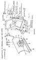
- Figure 1 is purely schematically a coupling 1 of a child trolley represented, for example, in the form of a tractor.
- the preferred at the Front of the pedal vehicle mounted clutch (but also at the rear can be provided) contains two spaced one above the other Coupling 2,3, which have such a distance from each other that a transverse wall portion 4 of a total with the reference numeral 5 designated, consisting of plastic adapter 5 substantially without vertical clearance between the coupling parts 2.3 fits.
- the adapter 5 on the front of the child trolley not shown, rests, are aligned Through holes 6.7 of the coupling 1 with a through hole 8 through the wall portion 4, so that a coupling pin 9 through the three holes can be plugged to the adapter 5 immovably on the Childrens vehicle to fix.
- the adapter 5 has two laterally spaced apart, upstanding Arms 9,10, on the outer sides of guide rails 11 are formed.
- the Guide rails 11, which are identical to the two arms 9, 10, have a long vertical section 12, which is arched in at the top end go over a short, down-going blind hole 13.
- the blind hole 13 goes up to the top 14 by the insertion of guide pins 15, 16th to allow a metal bracket 17.
- the bracket 17 has an inverted U-shape in an end view (Figure 3A) a in the installed position upper cross member 18 and two parallel side rails 19.
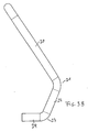
- the side rails 19 have in the side view ( Figure 3B) in the installed position an obliquely forwardly extending portion 20 at a kink 21st in a turn obliquely angled forward section 22, the at a further kink point 23 in a horizontal position in the installation position End section 24 passes.
- the bracket 17 engages each with a pin 15 of the Section 20 and a pin 16 of the section 22 in the lowered Working position of the snow blade 25 in the long vertical section 12 of the guide rail or a guide groove.
- the bracket 17 is raised and pivoted to the rear, that the two pins 15 in the associated Enter blind hole 13. From this position they can only by renewed Lifting and pivoting of the bracket 17 are released.
- the adapter 5 has two lateral lugs 26 with a support surface 27 for the associated portion 22 of the bracket 17 whose inclination coincides.
- a coupling element 28th plugged by the two ends 24 in tubular recesses laterally Lugs 29 of the coupling element 28 inserted and therein, for example are bolted.
- the coupling element 28 has a rotation axis in the Angle adjustment of the snow blade 25 serving hole 30 and a in Longitudinal direction of the child pedal vehicle hereby spaced second hole 31st
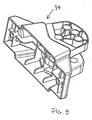
- the height of the coupling piece 28 is substantially consistent with the clear Distance between two projections 32 and 33 of a shield adapter 34 match.
- the Shield adapter 34 is attached to the back of the snow blade 25, preferably screwed.
- FIG. 6 shows, largely schematically, the front end section of two a child pedal vehicle not shown attached arms 40, which means a mechanism not shown can be raised and lowered.
- the two Arms 40 are connected together by means of a molding 41, the Contains recesses 42, in the protruding webs 43 of an adapter 44 used are bar.
- Bolts 45 are through aligned holes 46th and 47 in the recesses 42 delimiting walls and the webs 43rd guided, whereby the adapter 44 fixed to the two arms 40 of the Child pedal vehicle is attached.
Landscapes
- Engineering & Computer Science (AREA)
- Mechanical Engineering (AREA)
- Preparation Of Compounds By Using Micro-Organisms (AREA)
- Auxiliary Drives, Propulsion Controls, And Safety Devices (AREA)
- Motorcycle And Bicycle Frame (AREA)
- Handcart (AREA)
- Table Equipment (AREA)
- Body Structure For Vehicles (AREA)
- Pharmaceuticals Containing Other Organic And Inorganic Compounds (AREA)
- Transition And Organic Metals Composition Catalysts For Addition Polymerization (AREA)
- Vehicle Step Arrangements And Article Storage (AREA)
- Braking Elements And Transmission Devices (AREA)
- Acyclic And Carbocyclic Compounds In Medicinal Compositions (AREA)
- Compounds Of Unknown Constitution (AREA)
- Toys (AREA)
- Non-Portable Lighting Devices Or Systems Thereof (AREA)
- Lighting Device Outwards From Vehicle And Optical Signal (AREA)
- Vehicle Interior And Exterior Ornaments, Soundproofing, And Insulation (AREA)
- Carriages For Children, Sleds, And Other Hand-Operated Vehicles (AREA)
Abstract
Description
- Figur 1
- eine Ausführungsform einer Anordnung aus einer Adaptereinrichtung und einem Schneeräumschild in einer skizzenhaften auseinandergezogenen Darstellung;
- Figur 2
- den Adapter gemäß Figur 1 in vergrößerter Darstellung;
- Figuren 3a bis 3c
- eine Stirnansicht, Seitenansicht und eine Aufsicht des Bügels der Ausführungsform gemäß Figur 1;
- Figur 4
- das Kupplungselement der Ausführungsform der Figur 1;
- Figur 5
- den Schildadapter der gemäß Figur 1;
- Figur 6
- eine zweite Ausführungsform einer Anordnung aus einem Adapter und einem Schneeräumschild für ein Kindertretfahrzeug mit heb- und senkbaren Armen in einer skizzenhaften auseinandergezogenen Darstellung;
- Figur 7
- eine perspektivische Ansicht der beiden Arme gemäß Figur 6;
- Figur 8
- eine perspektivische Ansicht des Adapters gemäß Figur 6, und
- Figur 9
- den Schildadapter.
Claims (10)
- Kindertretfahrzeug,
gekennzeichnet durch
ein Schneeräumschild (25), das über eine Adaptereinrichtung (5,44) mit dem Kindertretfahrzeug verbindbar ist. - Kindertretfahrzeug nach Anspruch 1,
dadurch gekennzeichnet, daß das Schneeräumschild (25) in verschiedenen Winkelstellungen zur Längsrichtung des Kindertretfahrzeugs an der Adaptereinrichtung (5,44) fixierbar ist. - Kindertretfahrzeug nach Anspruch 1 oder 2,
dadurch gekennzeichnet, daß das Schneeräumschild (25) vertikal bewegbar gehalten ist. - Kindertretfahrzeug nach einem der Ansprüche 1 bis 3, wobei das Kindertretfahrzeug mit einer Kupplungseinrichtung versehen ist,
dadurch gekennzeichnet, daß ein Adapter (5) an der Kupplungseinrichtung (1) befestigbar ist, der zwei seitlich voneinander beabstandete Führungseinrichtungen (11) für einen Bügel (17) aufweist, der mit einem Kupplungselement (28) für einen an dem Schneeräumschild (25) befestigten Schildadapter (34) verbunden ist, wobei der Bügel (17) in der Führungseinrichtung (11) über einen vorgegebenen Bereich vertikal anhebbar und in einer angehobenen Lage so verschwenkbar ist, daß der Bügel (17) in dieser Lage fixiert ist. - Kindertretfahrzeug nach Anspruch 4,
dadurch gekennzeichnet, daß der Bügel (17) in einer Vorderansicht eine umgekehrte U-Form hat und daß das Kupplungselement (28) auf die freien Enden (24) des Bügels (17) aufgesteckt ist. - Kindertretfahrzeug nach Anspruch 4 oder 5,
dadurch gekennzeichnet, daß die beiden parallelen Holme (19) des Bügels (17) einen geradlinigen oberen Abschnitt (20) und einen davon abgewinkelten unteren Abschnitt (22) aufweisen, und daß die Holme (19) oberhalb und unterhalb der Knickstelle (21) jeweils einen nach innen vorstehenden Zapfen (15, 16) aufweisen, die in die Führungseinrichtung (11) eingreifen. - Kindertretfahrzeug nach einem der Ansprüche 4 bis 6,
dadurch gekennzeichnet, daß die Führungseinrichtungen (11) jeweils eine lange vertikale Führungsbahn (12) aufweisen, die am oberen Ende bogenförmig in eine kurze, im wesentlichen vertikal nach unten verlaufende Führungsbahn (13) übergeht. - Kindertretfahrzeug nach einem der Ansprüche 4 bis 7,
dadurch gekennzeichnet, daß das Kupplungselement (28) zwei in Längsrichtung des Tretfahrzeugs beabstandete Bohrungen (30,31) aufweist, und daß der Schildadapter (34) eine zur Seite des Schneeräumschildes (25) liegende Bohrung (35) und bevorzugt drei weitere Bohrungen (36, 37, 38) enthält, die auf einem Kreisbogen liegen, dessen Radius mit dem Abstand der zwei Bohrungen (30,31) des Kupplungselementes (28) übereinstimmt. - Kindertretfahrzeug nach einem der Ansprüche 4 bis 8,
dadurch gekennzeichnet, daß der Schildadapter (34) zwei übereinanderliegende Abschnitte (32,33) aufweist, zwischen die das Kupplungselement (28) im wesentlichen ohne vertikales Spiel paßt. - Kindertretfahrzeug nach einem der Ansprüche 1 bis 3, wobei das Kindertretfahrzeug zwei seitlich beabstandete, anhebbare und absenkbare aufweist,
dadurch gekennzeichnet, daß ein mit einem Kupplungselement (48) versehender Adapter (44) an den beiden Armen anbringbar ist und
daß das Kupplungselement (48) mit einem an dem Schneeräumschild (25) befestigten Schildadapter (34) koppelbar ist.
Priority Applications (1)
| Application Number | Priority Date | Filing Date | Title |
|---|---|---|---|
| PL04016281T PL1502845T3 (pl) | 2003-07-30 | 2004-07-10 | Pojazd dla dzieci |
Applications Claiming Priority (2)
| Application Number | Priority Date | Filing Date | Title |
|---|---|---|---|
| DE10334749A DE10334749B4 (de) | 2003-07-30 | 2003-07-30 | Kindertretfahrzeug |
| DE10334749 | 2003-07-30 |
Publications (3)
| Publication Number | Publication Date |
|---|---|
| EP1502845A2 true EP1502845A2 (de) | 2005-02-02 |
| EP1502845A3 EP1502845A3 (de) | 2006-04-12 |
| EP1502845B1 EP1502845B1 (de) | 2007-09-12 |
Family
ID=33521482
Family Applications (1)
| Application Number | Title | Priority Date | Filing Date |
|---|---|---|---|
| EP04016281A Expired - Lifetime EP1502845B1 (de) | 2003-07-30 | 2004-07-10 | Kindertretfahrzeug |
Country Status (7)
| Country | Link |
|---|---|
| EP (1) | EP1502845B1 (de) |
| AT (1) | ATE372919T1 (de) |
| DE (2) | DE10334749B4 (de) |
| DK (1) | DK1502845T3 (de) |
| ES (1) | ES2294403T3 (de) |
| NO (1) | NO324186B1 (de) |
| PL (1) | PL1502845T3 (de) |
Family Cites Families (8)
| Publication number | Priority date | Publication date | Assignee | Title |
|---|---|---|---|---|
| US2455692A (en) * | 1947-03-27 | 1948-12-07 | Frederick A Mcdunnah | Velocipede toy shovel attachment |
| US2776767A (en) * | 1954-01-28 | 1957-01-08 | Verne H Stover | Dozer and loading attachment for tricycles |
| US2816772A (en) * | 1955-06-07 | 1957-12-17 | Lapointe Alfred | Child's wagon with obstacle clearing guard |
| DE1975663U (de) * | 1967-08-08 | 1967-12-21 | Karlmann Kutschka Spielwarenfa | Spielfahrzeug. |
| DE2000038A1 (de) * | 1970-01-02 | 1971-07-08 | Basf Ag | Verfahren zum Faerben von Celluloseestern |
| DE8901489U1 (de) * | 1989-02-09 | 1989-04-06 | BIG-Spielwarenfabrik Dipl.-Ing. Ernst A. Bettag, 8510 Fürth | Fahrbares Kinderspielzeug |
| DE19600440C1 (de) * | 1996-01-09 | 1997-04-03 | Schneider Gmbh & Co Kg Franz | Kinderspielzeug |
| DE20000385U1 (de) * | 2000-01-11 | 2001-06-07 | Preis, Erwin, 88178 Heimenkirch | Schneepflug für Kindertretmobile u.dgl. |
-
2003
- 2003-07-30 DE DE10334749A patent/DE10334749B4/de not_active Expired - Lifetime
-
2004
- 2004-07-10 ES ES04016281T patent/ES2294403T3/es not_active Expired - Lifetime
- 2004-07-10 DE DE502004004925T patent/DE502004004925D1/de not_active Expired - Lifetime
- 2004-07-10 PL PL04016281T patent/PL1502845T3/pl unknown
- 2004-07-10 DK DK04016281T patent/DK1502845T3/da active
- 2004-07-10 AT AT04016281T patent/ATE372919T1/de active
- 2004-07-10 EP EP04016281A patent/EP1502845B1/de not_active Expired - Lifetime
- 2004-07-27 NO NO20043194A patent/NO324186B1/no unknown
Also Published As
| Publication number | Publication date |
|---|---|
| DE10334749B4 (de) | 2007-01-25 |
| DE502004004925D1 (de) | 2007-10-25 |
| NO20043194L (no) | 2005-01-31 |
| NO324186B1 (no) | 2007-09-03 |
| DE10334749A1 (de) | 2005-02-24 |
| ES2294403T3 (es) | 2008-04-01 |
| EP1502845A3 (de) | 2006-04-12 |
| EP1502845B1 (de) | 2007-09-12 |
| DK1502845T3 (da) | 2008-01-21 |
| PL1502845T3 (pl) | 2008-04-30 |
| ATE372919T1 (de) | 2007-09-15 |
Similar Documents
| Publication | Publication Date | Title |
|---|---|---|
| DE60211493T2 (de) | Rollbare gehhilfe mit einer vorrichtung zur erleichterung des fahrens | |
| EP1925754B1 (de) | Zweiwegebagger | |
| DE4403715A1 (de) | Anhängervorrichtung für den rückseitigen Anbau an ein Fahrzeug, insbesondere einen PKW | |
| DE29911652U1 (de) | Fahrzeug-Lenkkopf | |
| EP1632275B1 (de) | Kinderspielfahrzeug | |
| EP1502845B1 (de) | Kindertretfahrzeug | |
| EP2213347B1 (de) | Anhänger für ein Kinderfahrzeug | |
| DE10137802A1 (de) | Vorrichtung zur selbstfahrenden Bearbeitung einer Reitbahn | |
| DE20313069U1 (de) | Kindertretfahrzeug | |
| EP1362772B1 (de) | Fahrzeug zum Umsetzen von Kompostmieten | |
| DE2322504B2 (de) | Fahrzeug mit knicklenkung | |
| DE2327982C2 (de) | Einspuriger lenkbarer Kufenschlitten | |
| DE3541769C2 (de) | ||
| DE29715943U1 (de) | Kunststoff-Kinderauto und Kinderfahrmobil | |
| DE8603784U1 (de) | Kinderwagen | |
| DE1655081C2 (de) | Abschleppgerät für Kraftfahrzeuge | |
| DE2203660C3 (de) | Reserveradhalter | |
| DE1986932U (de) | Motorfahrzeug, insbesondere Ackerschlepper, mit Uberschlagschutzbugel | |
| DE202014000039U1 (de) | Tragwagen für Gokarts | |
| DE3922205A1 (de) | Trittstufe fuer nutzfahrzeuge | |
| DE1605873A1 (de) | Sport- und Spielfahrzeug | |
| DE7013285U (de) | Frontlader. | |
| EP1086877A2 (de) | Bevorzugt Personen tragend verwendbare Vorrichtung zur Fortbewegung auf einer Bodenoberfläche | |
| DE3022219A1 (de) | Kinder-ski | |
| DE8533274U1 (de) | Pferdetransport-Anhänger |
Legal Events
| Date | Code | Title | Description |
|---|---|---|---|
| PUAI | Public reference made under article 153(3) epc to a published international application that has entered the european phase |
Free format text: ORIGINAL CODE: 0009012 |
|
| AK | Designated contracting states |
Kind code of ref document: A2 Designated state(s): AT BE BG CH CY CZ DE DK EE ES FI FR GB GR HU IE IT LI LU MC NL PL PT RO SE SI SK TR |
|
| AX | Request for extension of the european patent |
Extension state: AL HR LT LV MK |
|
| PUAL | Search report despatched |
Free format text: ORIGINAL CODE: 0009013 |
|
| AK | Designated contracting states |
Kind code of ref document: A3 Designated state(s): AT BE BG CH CY CZ DE DK EE ES FI FR GB GR HU IE IT LI LU MC NL PL PT RO SE SI SK TR |
|
| AX | Request for extension of the european patent |
Extension state: AL HR LT LV MK |
|
| 17P | Request for examination filed |
Effective date: 20061006 |
|
| 17Q | First examination report despatched |
Effective date: 20061107 |
|
| AKX | Designation fees paid |
Designated state(s): AT BE BG CH CY CZ DE DK EE ES FI FR GB GR HU IE IT LI LU MC NL PL PT RO SE SI SK TR |
|
| GRAP | Despatch of communication of intention to grant a patent |
Free format text: ORIGINAL CODE: EPIDOSNIGR1 |
|
| GRAS | Grant fee paid |
Free format text: ORIGINAL CODE: EPIDOSNIGR3 |
|
| GRAA | (expected) grant |
Free format text: ORIGINAL CODE: 0009210 |
|
| AK | Designated contracting states |
Kind code of ref document: B1 Designated state(s): AT BE BG CH CY CZ DE DK EE ES FI FR GB GR HU IE IT LI LU MC NL PL PT RO SE SI SK TR |
|
| REG | Reference to a national code |
Ref country code: GB Ref legal event code: FG4D Free format text: NOT ENGLISH |
|
| REG | Reference to a national code |
Ref country code: CH Ref legal event code: EP |
|
| REF | Corresponds to: |
Ref document number: 502004004925 Country of ref document: DE Date of ref document: 20071025 Kind code of ref document: P |
|
| REG | Reference to a national code |
Ref country code: IE Ref legal event code: FG4D Free format text: LANGUAGE OF EP DOCUMENT: GERMAN |
|
| GBT | Gb: translation of ep patent filed (gb section 77(6)(a)/1977) |
Effective date: 20071121 |
|
| REG | Reference to a national code |
Ref country code: SE Ref legal event code: TRGR |
|
| REG | Reference to a national code |
Ref country code: CH Ref legal event code: NV Representative=s name: KIRKER & CIE S.A. |
|
| REG | Reference to a national code |
Ref country code: DK Ref legal event code: T3 |
|
| NLV1 | Nl: lapsed or annulled due to failure to fulfill the requirements of art. 29p and 29m of the patents act | ||
| REG | Reference to a national code |
Ref country code: ES Ref legal event code: FG2A Ref document number: 2294403 Country of ref document: ES Kind code of ref document: T3 |
|
| PG25 | Lapsed in a contracting state [announced via postgrant information from national office to epo] |
Ref country code: GR Free format text: LAPSE BECAUSE OF FAILURE TO SUBMIT A TRANSLATION OF THE DESCRIPTION OR TO PAY THE FEE WITHIN THE PRESCRIBED TIME-LIMIT Effective date: 20071213 Ref country code: NL Free format text: LAPSE BECAUSE OF FAILURE TO SUBMIT A TRANSLATION OF THE DESCRIPTION OR TO PAY THE FEE WITHIN THE PRESCRIBED TIME-LIMIT Effective date: 20070912 |
|
| REG | Reference to a national code |
Ref country code: IE Ref legal event code: FD4D Ref country code: PL Ref legal event code: T3 |
|
| ET | Fr: translation filed | ||
| PG25 | Lapsed in a contracting state [announced via postgrant information from national office to epo] |
Ref country code: PT Free format text: LAPSE BECAUSE OF FAILURE TO SUBMIT A TRANSLATION OF THE DESCRIPTION OR TO PAY THE FEE WITHIN THE PRESCRIBED TIME-LIMIT Effective date: 20080212 Ref country code: SK Free format text: LAPSE BECAUSE OF FAILURE TO SUBMIT A TRANSLATION OF THE DESCRIPTION OR TO PAY THE FEE WITHIN THE PRESCRIBED TIME-LIMIT Effective date: 20070912 |
|
| PG25 | Lapsed in a contracting state [announced via postgrant information from national office to epo] |
Ref country code: RO Free format text: LAPSE BECAUSE OF FAILURE TO SUBMIT A TRANSLATION OF THE DESCRIPTION OR TO PAY THE FEE WITHIN THE PRESCRIBED TIME-LIMIT Effective date: 20070912 |
|
| PLBE | No opposition filed within time limit |
Free format text: ORIGINAL CODE: 0009261 |
|
| STAA | Information on the status of an ep patent application or granted ep patent |
Free format text: STATUS: NO OPPOSITION FILED WITHIN TIME LIMIT |
|
| 26N | No opposition filed |
Effective date: 20080613 |
|
| PG25 | Lapsed in a contracting state [announced via postgrant information from national office to epo] |
Ref country code: IE Free format text: LAPSE BECAUSE OF FAILURE TO SUBMIT A TRANSLATION OF THE DESCRIPTION OR TO PAY THE FEE WITHIN THE PRESCRIBED TIME-LIMIT Effective date: 20070912 |
|
| PGFP | Annual fee paid to national office [announced via postgrant information from national office to epo] |
Ref country code: CZ Payment date: 20080704 Year of fee payment: 5 Ref country code: FI Payment date: 20080702 Year of fee payment: 5 Ref country code: PL Payment date: 20080703 Year of fee payment: 5 |
|
| PGFP | Annual fee paid to national office [announced via postgrant information from national office to epo] |
Ref country code: GB Payment date: 20080716 Year of fee payment: 5 |
|
| PGFP | Annual fee paid to national office [announced via postgrant information from national office to epo] |
Ref country code: TR Payment date: 20080707 Year of fee payment: 5 |
|
| REG | Reference to a national code |
Ref country code: DK Ref legal event code: EBP |
|
| PG25 | Lapsed in a contracting state [announced via postgrant information from national office to epo] |
Ref country code: MC Free format text: LAPSE BECAUSE OF NON-PAYMENT OF DUE FEES Effective date: 20080731 |
|
| PG25 | Lapsed in a contracting state [announced via postgrant information from national office to epo] |
Ref country code: EE Free format text: LAPSE BECAUSE OF FAILURE TO SUBMIT A TRANSLATION OF THE DESCRIPTION OR TO PAY THE FEE WITHIN THE PRESCRIBED TIME-LIMIT Effective date: 20070912 |
|
| PG25 | Lapsed in a contracting state [announced via postgrant information from national office to epo] |
Ref country code: SI Free format text: LAPSE BECAUSE OF FAILURE TO SUBMIT A TRANSLATION OF THE DESCRIPTION OR TO PAY THE FEE WITHIN THE PRESCRIBED TIME-LIMIT Effective date: 20070912 |
|
| PG25 | Lapsed in a contracting state [announced via postgrant information from national office to epo] |
Ref country code: CY Free format text: LAPSE BECAUSE OF FAILURE TO SUBMIT A TRANSLATION OF THE DESCRIPTION OR TO PAY THE FEE WITHIN THE PRESCRIBED TIME-LIMIT Effective date: 20070912 Ref country code: DK Free format text: LAPSE BECAUSE OF NON-PAYMENT OF DUE FEES Effective date: 20080731 |
|
| PG25 | Lapsed in a contracting state [announced via postgrant information from national office to epo] |
Ref country code: BG Free format text: LAPSE BECAUSE OF FAILURE TO SUBMIT A TRANSLATION OF THE DESCRIPTION OR TO PAY THE FEE WITHIN THE PRESCRIBED TIME-LIMIT Effective date: 20071212 |
|
| REG | Reference to a national code |
Ref country code: ES Ref legal event code: FD2A Effective date: 20080711 |
|
| PG25 | Lapsed in a contracting state [announced via postgrant information from national office to epo] |
Ref country code: ES Free format text: LAPSE BECAUSE OF NON-PAYMENT OF DUE FEES Effective date: 20080711 |
|
| GBPC | Gb: european patent ceased through non-payment of renewal fee |
Effective date: 20090710 |
|
| PG25 | Lapsed in a contracting state [announced via postgrant information from national office to epo] |
Ref country code: FI Free format text: LAPSE BECAUSE OF NON-PAYMENT OF DUE FEES Effective date: 20090710 Ref country code: CZ Free format text: LAPSE BECAUSE OF NON-PAYMENT OF DUE FEES Effective date: 20090710 |
|
| PG25 | Lapsed in a contracting state [announced via postgrant information from national office to epo] |
Ref country code: GB Free format text: LAPSE BECAUSE OF NON-PAYMENT OF DUE FEES Effective date: 20090710 |
|
| PG25 | Lapsed in a contracting state [announced via postgrant information from national office to epo] |
Ref country code: LU Free format text: LAPSE BECAUSE OF NON-PAYMENT OF DUE FEES Effective date: 20080710 Ref country code: HU Free format text: LAPSE BECAUSE OF FAILURE TO SUBMIT A TRANSLATION OF THE DESCRIPTION OR TO PAY THE FEE WITHIN THE PRESCRIBED TIME-LIMIT Effective date: 20080313 Ref country code: BE Free format text: LAPSE BECAUSE OF NON-PAYMENT OF DUE FEES Effective date: 20080731 |
|
| PG25 | Lapsed in a contracting state [announced via postgrant information from national office to epo] |
Ref country code: PL Free format text: LAPSE BECAUSE OF NON-PAYMENT OF DUE FEES Effective date: 20090710 |
|
| REG | Reference to a national code |
Ref country code: PL Ref legal event code: LAPE |
|
| PG25 | Lapsed in a contracting state [announced via postgrant information from national office to epo] |
Ref country code: TR Free format text: LAPSE BECAUSE OF NON-PAYMENT OF DUE FEES Effective date: 20090710 |
|
| REG | Reference to a national code |
Ref country code: FR Ref legal event code: PLFP Year of fee payment: 13 |
|
| REG | Reference to a national code |
Ref country code: FR Ref legal event code: PLFP Year of fee payment: 14 |
|
| REG | Reference to a national code |
Ref country code: FR Ref legal event code: PLFP Year of fee payment: 15 |
|
| P01 | Opt-out of the competence of the unified patent court (upc) registered |
Effective date: 20230519 |
|
| PGFP | Annual fee paid to national office [announced via postgrant information from national office to epo] |
Ref country code: IT Payment date: 20230731 Year of fee payment: 20 Ref country code: CH Payment date: 20230802 Year of fee payment: 20 Ref country code: AT Payment date: 20230726 Year of fee payment: 20 |
|
| PGFP | Annual fee paid to national office [announced via postgrant information from national office to epo] |
Ref country code: SE Payment date: 20230720 Year of fee payment: 20 Ref country code: FR Payment date: 20230720 Year of fee payment: 20 Ref country code: DE Payment date: 20230829 Year of fee payment: 20 |
|
| REG | Reference to a national code |
Ref country code: DE Ref legal event code: R071 Ref document number: 502004004925 Country of ref document: DE |
|
| REG | Reference to a national code |
Ref country code: CH Ref legal event code: PL |
|
| REG | Reference to a national code |
Ref country code: AT Ref legal event code: MK07 Ref document number: 372919 Country of ref document: AT Kind code of ref document: T Effective date: 20240710 |
|
| REG | Reference to a national code |
Ref country code: SE Ref legal event code: EUG |