EP1502894B1 - Appareil de manutention de charge - Google Patents
Appareil de manutention de charge Download PDFInfo
- Publication number
- EP1502894B1 EP1502894B1 EP04014729A EP04014729A EP1502894B1 EP 1502894 B1 EP1502894 B1 EP 1502894B1 EP 04014729 A EP04014729 A EP 04014729A EP 04014729 A EP04014729 A EP 04014729A EP 1502894 B1 EP1502894 B1 EP 1502894B1
- Authority
- EP
- European Patent Office
- Prior art keywords
- actuator
- lifting arm
- cylinder
- fluid
- displacement device
- Prior art date
- Legal status (The legal status is an assumption and is not a legal conclusion. Google has not performed a legal analysis and makes no representation as to the accuracy of the status listed.)
- Expired - Lifetime
Links
- 239000012530 fluid Substances 0.000 claims abstract description 102
- 238000006073 displacement reaction Methods 0.000 claims abstract description 68
- 238000000034 method Methods 0.000 claims description 6
- 238000010586 diagram Methods 0.000 description 1
- 239000000463 material Substances 0.000 description 1
- 238000012986 modification Methods 0.000 description 1
- 230000004048 modification Effects 0.000 description 1
- 230000000717 retained effect Effects 0.000 description 1
Images

Classifications
-
- B—PERFORMING OPERATIONS; TRANSPORTING
- B66—HOISTING; LIFTING; HAULING
- B66F—HOISTING, LIFTING, HAULING OR PUSHING, NOT OTHERWISE PROVIDED FOR, e.g. DEVICES WHICH APPLY A LIFTING OR PUSHING FORCE DIRECTLY TO THE SURFACE OF A LOAD
- B66F9/00—Devices for lifting or lowering bulky or heavy goods for loading or unloading purposes
- B66F9/06—Devices for lifting or lowering bulky or heavy goods for loading or unloading purposes movable, with their loads, on wheels or the like, e.g. fork-lift trucks
- B66F9/065—Devices for lifting or lowering bulky or heavy goods for loading or unloading purposes movable, with their loads, on wheels or the like, e.g. fork-lift trucks non-masted
- B66F9/0655—Devices for lifting or lowering bulky or heavy goods for loading or unloading purposes movable, with their loads, on wheels or the like, e.g. fork-lift trucks non-masted with a telescopic boom
-
- B—PERFORMING OPERATIONS; TRANSPORTING
- B66—HOISTING; LIFTING; HAULING
- B66F—HOISTING, LIFTING, HAULING OR PUSHING, NOT OTHERWISE PROVIDED FOR, e.g. DEVICES WHICH APPLY A LIFTING OR PUSHING FORCE DIRECTLY TO THE SURFACE OF A LOAD
- B66F9/00—Devices for lifting or lowering bulky or heavy goods for loading or unloading purposes
- B66F9/06—Devices for lifting or lowering bulky or heavy goods for loading or unloading purposes movable, with their loads, on wheels or the like, e.g. fork-lift trucks
- B66F9/075—Constructional features or details
- B66F9/20—Means for actuating or controlling masts, platforms, or forks
- B66F9/22—Hydraulic devices or systems
-
- E—FIXED CONSTRUCTIONS
- E02—HYDRAULIC ENGINEERING; FOUNDATIONS; SOIL SHIFTING
- E02F—DREDGING; SOIL-SHIFTING
- E02F3/00—Dredgers; Soil-shifting machines
- E02F3/04—Dredgers; Soil-shifting machines mechanically-driven
- E02F3/28—Dredgers; Soil-shifting machines mechanically-driven with digging tools mounted on a dipper- or bucket-arm, i.e. there is either one arm or a pair of arms, e.g. dippers, buckets
- E02F3/36—Component parts
- E02F3/42—Drives for dippers, buckets, dipper-arms or bucket-arms
- E02F3/43—Control of dipper or bucket position; Control of sequence of drive operations
- E02F3/431—Control of dipper or bucket position; Control of sequence of drive operations for bucket-arms, front-end loaders, dumpers or the like
- E02F3/432—Control of dipper or bucket position; Control of sequence of drive operations for bucket-arms, front-end loaders, dumpers or the like for keeping the bucket in a predetermined position or attitude
- E02F3/433—Control of dipper or bucket position; Control of sequence of drive operations for bucket-arms, front-end loaders, dumpers or the like for keeping the bucket in a predetermined position or attitude horizontal, e.g. self-levelling
Definitions
- This invention relates to a load handling machine and more particularly to a load handling machine which includes a body, a lifting arm pivotally mounted at or adjacent one end to the body for pivotal movement about a first generally horizontal pivot axis, and the lifting arm carrying at a second end opposite to the first end, a load handling implement, which is mounted for pivotal movement relative to the lifting arm about a second generally horizontal pivot axis.
- a first fluid operated linear actuator is provided which is pivotally mounted at respective first and second ends to the body of the machine at one side of the first pivot axis, and to the lifting arm.
- a second fluid operated linear actuator is provided, typically mounted within the lifting arm, or at least above the second pivot axis, which acts to pivot the load handling implement about the second pivot axis relative to the lifting arm, through a lever, for maximum mechanical advantage.
- a linear displacement device which includes a piston moveable in a cylinder, which is pivotally mounted at respective first and second ends to the body of the machine at the opposite side of the first pivot axis as the first actuator, and to the lifting arm, so that as the lifting arm is raised, fluid is ejected from one side of the piston of the displacement device and is fed to the second actuator which extends, to pivot the load handling implement as the arm is raised, such that the attitude of the load handling implement relative to the ground is maintained.
- the lifting arm is lowered fluid is ejected from the other side of the piston of the displacement device and is fed to the second actuator, so that as the lifting arm lowers, the attitude of the load handling implement relative to the ground, is maintained.
- the second actuator typically is a piston and cylinder type actuator, and a fluid circuit is arranged so that for example, fluid is ejected from a non-annulus side of the displacement device as the arm is raised, and is fed to a non-annulus side of the second actuator as the arm is raised, and conversely, fluid is ejected from the annulus side of the displacement device as the arm is lowered, and is fed to the annulus side of the second actuator.
- a load may be reliably and mechanically maintained at a generally level attitude for example, during raising and lowering of the lifting arm, without operator intervention.
- a disadvantage with such a machine is that the lifting arm must extend beyond the first pivot axis, to provide a pivotal mounting for the displacement device. Moreover, particularly during raising of the lifting arm, fluid which is displaced from the displacement device, will provide a resistance to raising of the arm, which is inefficient.
- the displacement device mounts at the same one side of the first pivot axis as the first actuator. Thus no lifting arm extension beyond the first pivot axis is required.
- the displacement device will act oppositely to that described where the displacement device is at the opposite side of the first pivot axis to the first lifting actuator. That is, as the lifting arm is raised, fluid will be ejected from an annulus side of the displacement device, and as the lifting arm is lowered, fluid will be ejected from the non-annulus side of the displacement device.
- Fluid displaced from the annulus side of the displacement device during arm raising and from the non-annulus side of the displacement device during arm lowering cannot readily be arranged to be fed to the respective non-annulus and annulus sides of the second actuator to maintain the attitude of the load handling implement during both lifting and lowering.
- the second actuator tends to be mounted beneath the lifting arm so as to act between the lifting arm below the second pivot, to pivot the load handling implement.
- a machine in accordance with the invention may realise the advantage of a machine in which the displacement device is mounted on the body of the machine on the same side of the first pivot axis as the first lifting actuator, i.e. the length of the machine can be reduced as there is no requirement for a lifting arm extension beyond the lifting axis, whilst retaining the advantage of having the second actuator being provided above the second pivot axis, e.g. within the lifting arm, and acting to pivot the load handling implement, through a lever which provides maximum mechanical advantage.
- the volume of fluid ejected from the non-annulus side of the cylinder of the second actuator during lowering of the lifting arm is substantially the same as the combined changes in volumes of the annulus sides of the cylinders of the displacement device, and the volume of fluid ejected from annulus side of the cylinder of the second actuator during raising of the lifting arm, is substantially the same as the changing volume of the non-annulus side of the one cylinder of the displacement device.
- fluid pressure which is fed to the first actuator is transmitted to a the non-annulus side of at least one of the cylinders of the displacement device, which thus acts to assist the first actuator in raising the lifting arm.
- fluid from a fluid line to the first actuator may be fed to the non-annulus side of the other of the pair of cylinders of the displacement device, and if desired, a fluid line between the annulus side of the second actuator and the non-annulus side of the one of the pair of cylinders of the displacement device, may pressurised by fluid pressure from the fluid line to the first actuator, e.g. through a check valve, so that the one cylinder of the displacement device too may be pressurised and may assist raising of the arm.
- pressure in the fluid line to the first actuator may be relieved, so that fluid may pass from the non-annulus side of the other of the pair of cylinders of the displacement device, to low pressure.
- the fluid line for pressurised fluid to the first actuator to raise the lifting arm may each include a counterbalance valve, so that that in the event of a loss in pressure, e.g. due to the failure of a fluid line between on the one hand, the respective counterbalance valve and the first actuator, and on the other hand, the respective counterbalance valve and the second actuator, the geometry of the respective actuator will be retained. Thus the risk of a load being suddenly lowered or discharged from the working implement, will be reduced.
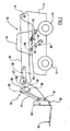
- a load handling machine 10 includes a body 11 mounted on a ground engaging structure which in this example includes a front pair of wheels 13 and a rear pair of wheels 14 whereby the machine 10 is moveable over the ground.
- the machine 10 includes an operator's cab 16 from which the machine 10 is controllable, and a lifting arm 18 for raising and lowering of a load on a load handling implement 19.
- the lifting arm 18 is mounted on the body 11 for up and down pivotal movement about a first generally horizontal axis A which in this example is positioned to the rear of the cab 16, but in another example may be in front of the cab 16.
- a first fluid operated linear actuator 20 is provided to raise and permit of lowering of the lifting arm 18, the actuator including a cylinder 21 pivotally mounted on the body 11, and a piston 22 linearly moveable in the cylinder 21, the piston 22 being fast with a piston rod 23 which is pivotally connected to a mounting 24 beneath the lifting arm 18, in front of the pivot axis A, so that as the first actuator 20 is extended, the lifting arm 18 is raised about the axis A, and as the first actuator is retracted, the lifting arm 18 may lower.
- the load handling implement 19 is a pair of lifting forks on a carriage 35, but these could be replaced by a bucket or any other desired load handling implement.
- the load handling implement 19 is pivotally mounted for pivotal movement about a second generally horizontal axis B, to the lifting arm 18, at an end of the lifting arm 18 remote from the first generally horizontal axis A.
- the lifting arm 18 may include a plurality of telescopic sections so that the load may be moved away from and towards the body 11 of the machine 10, in which case, the load handling implement would be provided on the outermost section.
- Pivoting of the load handling implement 19 about the second generally horizontal axis B is achieved by a second fluid operated linear actuator 25 which includes a cylinder 26, a piston 27 linearly moveable in the cylinder 26, and a piston rod 28 fast with the piston 27.
- the cylinder 26 is pivotally mounted inside the lifting arm 18, above the second generally horizontal axis B, and acts to pivot the load handling implement about the second generally horizontal axis B through a lever provided by a linkage mechanism 40.
- the piston rod 28 is pivotally mounted at 32 to a first link 30 of the mechanism 40, which first link 30 acts as a lever which is pivotally mounted to both a second link 31, at 33, and to the lifting arm 18, as indicated at 36 in the drawing, whereby maximum mechanical advantage can be achieved through the mechanism 40 as the second actuator 25 is extended and retracted.
- first link 30 acts as a lever which is pivotally mounted to both a second link 31, at 33, and to the lifting arm 18, as indicated at 36 in the drawing, whereby maximum mechanical advantage can be achieved through the mechanism 40 as the second actuator 25 is extended and retracted.
- the second link 31 extends between the first link 30 and a pivotal mounting 34 on a carriage 35 which carries the forks of the load handling implement 19.
- piston 27 of the second actuator 25 could be directly coupled to the carriage 35, above the second pivot axis B, where the particular geometry allows this.
- Such a linkage mechanism 40 is well known and further detailed description is not considered necessary.
- the linkage mechanism 40 is particularly effective where the load handling implement 19 is a bucket which may be required to dig into a pile of earth or the like, as the maximum mechanical advantage can be realised with the digging bucket at an appropriate angular position about the second generally horizontal axis B, for digging, which is typically where a lower surface of the bucket is generally level with the (level) ground.
- a displacement device 42 which includes a pair of cylinders 44a, 44b, each with respective pistons 45a, 45b linearly moveably mounted inside, each piston 45a, 45b being fast with a respective piston rod 46a, 46b.
- the cylinders 44a, 44b are each pivotally mounted to the body 11 of the machine 10, whilst the piston rods 46a, 46b are each pivotally mounted to the lifting arm 18 at respective pivotal connections 48 at the same side of the first generally horizontal axis A as the first lifting actuator 20.
- the pistons 45a, 45b in each of the cylinders 44a, 44b of the displacement device 42 will move linearly to extend the length of the displacement device 42, and conversely when the lifting arm 18 is permitted to lower, the length of the displacement device 42 will retract.
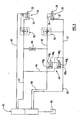
- a fluid flow control valve 50 is provided by means of which pressurised fluid from a pump may be controlled to be directed along a (lower as shown in the drawing) fluid line 51 to a non-annulus side of the cylinder 21 of the first actuator 20, to extend the actuator 20, thus to raise the lifting arm 18 and at the same time to permit fluid ejected from an annulus side of the cylinder 21 of the first actuator 20 to flow to a low pressure region along a, (upper as shown in the drawing) return, fluid line 52, or alternatively to control pressurised fluid to be directed along the upper line 52 to the annulus side of the cylinder 21 of the first actuator 20 to permit the lifting arm 18 to lower and at the same time to allow fluid ejected from the non-annulus side of the cylinder 21 of the first actuator 20 to pass along the lower fluid line 51 to a low pressure region, e.g. tank 55.
- a low pressure region e.g. tank 55.
- a counterbalance valve 53 In the lower fluid line 51 along which the pressurised fluid passes to the non-annulus side of the cylinder 21 of the first actuator 20 to raise the lifting arm 18, there is provided a counterbalance valve 53, to prevent the sudden lowering of the lifting arm 18 in the event of the failure of either of the fluid lines 51, 52, as is known in the art.
- a (upper as seen in the drawing) fluid line 56 is provided between the annulus side of the piston 27 of the second fluid operated linear actuator 25 and the non-annulus side of the one cylinder 44a (the upper as seen in the drawing) of the pair of cylinders 44a, 44b of the displacement device 42, and a further (lower as seen in the drawing) fluid line 57 is provided between the non-annulus side of the cylinder 26 of the second actuator 25 and both of the annulus sides of the cylinders 44a, 44b of the displacement device 42.
- Another fluid line 58 extends between the non-annulus side of the other cylinder 44b of the pair of cylinders 44a, 44b of the displacement device 42 and the lower fluid line 51 between the control valve 50 and the non-annulus side of the cylinder 21 of the first actuator 20.
- Respective fluid lines 59, 60 extend between the upper fluid line 56 to the annulus side of the cylinder 26 of the second actuator 25, and the flow control valve 50, and between the lower fluid line 57 to the non-annulus side of the cylinder 26 of the second actuator 20 and the flow control valve 50, so that the second actuator 25 may when required, be operated to tilt the loading implement 19 about the second generally horizontal axis B under operator control.
- the fluid system operated as follows.
- the fluid lines 59, 60 from the flow control valve 50 to the second actuator 25 may be closed by the flow control valve 50.
- the piston rods 46a, 46b of the displacement device 42 will be moved outwardly from their respective cylinders 44a, 44b to extend the displacement device 42.
- Fluid at the arm lift pressure in the lower fluid line 51 to the first actuator 20 will be communicated to the non-annulus side of the piston 45b of the lower cylinder 44b of the displacement device 42 to assist raising of the arm 18, and fluid pressure from the lower fluid line 51 to the first actuator 20 will also be communicated, via a check valve 65 to the upper fluid line 56 to the second actuator 25, and hence to the non-annulus side of the upper cylinder 44a, of the displacement device 42 to assist raising of the lifting arm 18.
- Fluid which is ejected from the annulus side of the cylinder 26 of the second actuator 25 will be communicated to the non-annulus side of the piston 45a of the one only (upper) of the cylinders 44a of the displacement device 42, via the second counterbalance valve 62.
- fluid will be ejected from each of the annulus sides of the cylinders 44a, 44b of the displacement device 42 and will pass along the lower fluid line 57 to the non-annulus side of the second actuator 25 thus causing piston 27 of the second actuator 25 to move in its cylinder 26.
- the volume of fluid ejected from the cylinders 44a, 44b of the displacement device 42 is substantially equal to the changing volume of the non-annulus side of the cylinder 26 of the second actuator, so that the load handling implement 19 is caused to pivot about the second generally pivotal axis B by an amount proportional to the changing angle of the lifting arm 18 about the first generally horizontal axis A, so the attitude of the load handling implement 19 relative to the ground, is maintained during arm 18 lifting.
- the volume of fluid ejected from the non-annulus side of the cylinder 26 of the second actuator 25 is again substantially equal to the changing volumes of annulus sides of the cylinder 44a, 44b of the displacement device 42.
- the load handling implement 19 is caused to pivot about the second generally pivotal axis B by an amount proportional to the changing angle of the lifting arm 18 about the first generally horizontal axis A, but oppositely to the pivot direction during lifting arm 18 raising, so the attitude of the load handling implement 19 relative to the ground, is maintained during arm 18 lowering.
- Fluid ejected from the non-annulus side of the lower cylinder 44b of the displacement device 42 passes along the fluid line 58 to the lower fluid line 51 to the first actuator 20, and hence to the low pressure region 55.
- counterbalance valves 53, 62 may be changed depending upon the detailed nature of the hydraulic circuit, and instead of or in addition to the check valve 65 in the line 56 from the lower fluid line to the first actuator 20 and the upper fluid line to the second actuator, another valve to maintain pressure in the fluid line 56 to the second actuator 25 may be provided.
- the flow control valve 50 is preferably a spool valve having separate spools for separately controlling the flow of fluid to the first actuator 20 and the second actuator 25, although other flow control valve arrangements, e.g. separate flow control valves for each actuator 20, 25 may be provided.
- the lifting arm 18 may be raised and lowered whilst the attitude of the load is maintained without operator intervention, and by providing a pair of displacement cylinder 44a, 44b in a circuit as described, these may be positioned at the same side of the first generally horizontal axis A as the first actuator 20, whilst the second actuator 25 may be positioned above the second generally horizontal pivot axis B, within the lifting arm 18 as shown or elsewhere, and my thus act to pivot the load handling implement 19 about the second generally horizontal axis B through the lever provided by the linkage mechanism 40, whilst achieving the best mechanical advantage.
Landscapes
- Engineering & Computer Science (AREA)
- Structural Engineering (AREA)
- Mechanical Engineering (AREA)
- Transportation (AREA)
- Civil Engineering (AREA)
- Geology (AREA)
- Life Sciences & Earth Sciences (AREA)
- Chemical & Material Sciences (AREA)
- Combustion & Propulsion (AREA)
- General Engineering & Computer Science (AREA)
- Mining & Mineral Resources (AREA)
- Forklifts And Lifting Vehicles (AREA)
- Polymers With Sulfur, Phosphorus Or Metals In The Main Chain (AREA)
- Centrifugal Separators (AREA)
- Fluid-Pressure Circuits (AREA)
- Manipulator (AREA)
- Operation Control Of Excavators (AREA)
- Earth Drilling (AREA)
- Electrical Discharge Machining, Electrochemical Machining, And Combined Machining (AREA)
- Supplying Of Containers To The Packaging Station (AREA)
Claims (12)
- Une machine de manutention de charge (10) comprenant un corps (11), un bras de levage (18) monté de manière pivotante à ou tout près d'une extrémité sur le corps (11) afin de permettre le pivotement sur un premier axe pivot généralement horizontal (A), le bras de levage (18) portant, à une deuxième extrémité opposée à la première, un outil de manutention de charge (19) monté de façon à permettre le mouvement de pivotement par rapport au bras de levage (18) sur un deuxième axe pivot généralement horizontal (B), un premier actionneur linéaire commandé par fluide (20) monté de manière pivotante aux première et deuxième extrémités respectives sur le corps (11) de la machine (20) d'un côté du premier axe pivot (A), et sur le bras de levage (18), pour lever et permettre l'abaissement du bras de levage (18) sur le premier axe pivot (A), et un deuxième actionneur linéaire commandé par fluide (25) pour faire pivoter l'outil de manutention de charge (19) sur le deuxième axe pivot (B), le deuxième actionneur (25) étant muni d'un piston (27) linéairement déplaçable dans un cylindre (26), le cylindre (26) ayant ainsi un côté couronne et un côté non-couronne, et dans lequel le deuxième actionneur (25) est monté au-dessus du deuxième axe pivot (B) et peut être utilisé pour faire pivoter l'outil de manutention de charge (19) à l'aide d'un levier (30,31) et se caractérisant par la présence d'un dispositif de déplacement linéaire (42) comprenant une paire de cylindres (44a, 44b) dont chacun est muni d'un piston linéairement déplaçable (45a, 45b), chaque cylindre (44a, 44b) ayant ainsi un côté couronne et un côté non-couronne et chaque cylindre (44a, 44b) étant monté de manière pivotante aux première et deuxième extrémités sur le corps (11) de la machine (10), du même côté du premier axe pivot (A) que le premier actionneur (20), et sur le bras de levage (18), le deuxième actionneur (25) et le dispositif de déplacement (42) étant interconnectés de manière telle que, lorsque le bras de levage (18) est abaissé, du fluide est éjecté d'un côté non-couronne d'un des cylindres (44a, 44b) du dispositif de déplacement (42) et est transmis à un côté couronne du deuxième actionneur (25), et lorsque le bras de levage (18) est levé, du fluide est éjecté des côtés couronne des deux cylindres (44a, 44b) du dispositif de déplacement (42) et transmis au côté non-couronne du cylindre (26) du deuxième actionneur (25) de façon à maintenir la position de l'outil de manutention de charge (19) par rapport au sol, pendant l'abaissement et le levage du bras de levage (18).
- Une machine conformément à la revendication 1, se caractérisant par le fait que le deuxième actionneur (25) est monté de manière pivotante à l'intérieur du bras de levage (18) et sert à faire pivoter l'outil de manutention de charge (19) par le biais d'un levier (30, 31).
- Une machine conformément à la revendication 1 ou 2, se caractérisant par le fait que le volume de fluide éjecté du côté non-couronne du cylindre (26) du deuxième actionneur (25) pendant l'abaissement du bras de levage (18) est pour l'essentiel le même que les changements de volume combinés des côtés couronne des cylindres (44a, 44b) du dispositif de déplacement (42), et que le volume de fluide éjecté du côté couronne du cylindre (26) du deuxième actionneur (25) pendant le levage du bras de levage (18) est pour essentiel le même que les changements de volume du côté non-couronne du cylindre (44a, 44b) du dispositif de déplacement (42).
- Une machine conformément à n'importe laquelle des revendications précédentes, se caractérisant par le fait que pendant le levage du bras de levage (18), la pression du fluide transmise au premier actionneur (20) est transmise au côté non-couronne d'au moins un des cylindres (44a, 44b) du dispositif de déplacement (42), ce qui aide le premier actionneur (20) à lever le bras de levage (18).
- Une machine conformément à la revendication 4 se caractérisant par le fait que, pendant le levage du bras de levage (18), le fluide allant d'une conduite de fluide (51) au premier actionneur (20) est transmis au côté non-couronne du deuxième cylindre (44b) de la paire de cylindres du dispositif de déplacement (42).
- Une machine conformément à la revendication 4 ou 5 se caractérisant par le fait qu'une conduite de fluide (57) entre le côté couronne du deuxième actionneur (25) et le côté non-couronne d'un des deux cylindres (44 a) du dispositif de déplacement (42) est mis sous pression par la pression du fluide allant de la conduite de fluide (51) au premier actionneur (20) de manière telle que le premier cylindre (44a) du dispositif de déplacement (42) puisse également aider à lever le bras de levage (18).
- Une machine conformément à la revendication 6 se caractérisant par le fait que la conduite de fluide (56) entre le côté couronne du deuxième actionneur (25) et le côté non-couronne du premier des deux cylindres (44a) du dispositif de déplacement (42) est mis sous pression par le biais d'un clapet anti-retour (65).
- Une machine conformément à n'importe laquelle des revendications 5 à 7, selon la revendication 5, se caractérisant par le fait que, pendant l'abaissement du bras de levage (18), la pression dans la conduite de fluide reliée au premier actionneur (20) est relâchée, afin que le fluide puisse arriver du côté non-couronne du deuxième cylindre (44b) de la paire de cylindres du dispositif de déplacement (42) à basse pression (55).
- Une machine conformément à n'importe laquelle des revendications précédentes, se caractérisant par le fait que la conduite de fluide (51) utilisée pour la transmission du fluide sous pression au premier actionneur (20) afin de lever le bras de levage comporte un clapet d'équilibrage (53).
- Une machine conformément à n'importe laquelle des revendications précédentes, se caractérisant par le fait que la conduite de fluide (56) entre le côté couronne du deuxième actionneur (25) et le côté non-couronne du premier cylindre (44a) du dispositif de déplacement (42) comporte un clapet d'équilibrage (62).
- Une méthode d'abaissement d'une charge portée sur un bras de levage (18) d'une machine de manutention de charge (10) du type dans lequel le bras de levage (18) est monté de manière pivotante à ou tout près d'une extrémité sur un corps (11) de la machine (10) pour le pivotement sur un premier axe pivot généralement horizontal (A), le bras de levage (18) portant à une deuxième extrémité opposée à la première un outil de manutention de charge (19) monté de façon à permettre le mouvement de pivotement par rapport au bras de levage (18) sur un deuxième axe pivot généralement horizontal (B), un premier actionneur linéaire commandé par fluide (20) monté de manière pivotante aux première et deuxième extrémités respectives sur le corps (11) de la machine (10) d'un côté du premier axe pivot (A), et sur le bras de levage (18), pour lever et permettre l'abaissement du bras de levage (18) sur le premier axe pivot (A), et un deuxième actionneur linéaire commandé par fluide (25) pour faire pivoter l'outil de manutention de charge (19) sur le deuxième axe pivot (B), le deuxième actionneur (25) étant muni d'un piston (27) pouvant se déplacer linéairement dans un cylindre (26), le cylindre (26) ayant ainsi un côté couronne et un côté non-couronne, et dans lequel le deuxième actionneur (25) est monté au-dessus du deuxième axe pivot (B) et peut être utilisé pour faire pivoter l'outil de manutention de charge (19) par le biais d'un levier (30,31), et se caractérisant par la présence d'un dispositif de déplacement linéaire (42) comportant une paire de cylindres (44a, 44b), chaque cylindre étant muni d'un piston linéairement déplaçable (45a, 45b), chaque cylindre (44a, 44b) ayant ainsi un côté couronne et un côté non-couronne, et chaque cylindre (44a, 44b) étant monté de manière pivotante aux première et deuxième extrémités respectives sur le corps (11) de la machine (10) du même côté du premier axe pivot (A) que le premier actionneur (20), et sur le bras de levage (18), la méthode comprenant, pendant l'abaissement du bras de levage (18), la transmission du fluide éjecté d'un côté non-couronne du premier (44a) des deux cylindres du dispositif de déplacement (42) à un côté couronne du deuxième actionneur (25), afin de maintenir la position de l'outil de manutention de charge (19) par rapport au sol pendant l'abaissement du bras de levage (18).
- Une méthode de levage d'une charge portée sur un bras de levage (18) d'une machine de manutention de charge (10) du type dans lequel le bras de levage (18) est monté de manière pivotante à ou tout près d'une extrémité sur un corps (11) de la machine (10) pour le pivotement sur un premier axe pivot généralement horizontal (A), et le bras de levage (18) portant à une deuxième extrémité opposée à la première un outil de manutention de charge (19) monté de façon à permettre le mouvement de pivotement par rapport au bras de levage (18) sur un deuxième axe pivot généralement horizontal (B), un premier actionneur linéaire commandé par fluide (20) monté de manière pivotante aux première et deuxième extrémités respectives sur le corps (11) de la machine (10) d'un côté du premier axe pivot (A), et sur le bras de levage (18), pour lever et permettre l'abaissement du bras de levage (18) sur le premier axe pivot (A), et un deuxième actionneur linéaire commandé par fluide (25) pour faire pivoter l'outil de manutention de charge (19) sur le deuxième axe pivot (B), le deuxième actionneur (25) étant muni d'un piston (27) pouvant se déplacer linéairement dans un cylindre (26), le cylindre (26) ayant ainsi un côté couronne et un côté non-couronne, et dans lequel le deuxième actionneur (25) est monté au-dessus du deuxième axe pivot (B) et peut être utilisé pour faire pivoter l'outil de manutention de charge (19) par le biais d'un levier (30,31), et se caractérisant par la présence d'un dispositif de déplacement linéaire (42) comportant une paire de cylindres (44a, 44b), chaque cylindre étant muni d'un piston linéairement déplaçable (45a, 45b), chaque cylindre (44a, 44b) ayant ainsi un côté couronne et un côté non-couronne et chaque cylindre (44a, 44b) étant monté de manière pivotante aux première et deuxième extrémités respectives sur le corps (11) de la machine (10) du même côté du premier axe pivot (A) que le premier actionneur (20), et sur le bras de levage (18), la méthode comprenant, pendant le levage du bras de levage (18), la transmission du fluide éjecté des côtés couronne des deux cylindres (44a, 44b) du dispositif de déplacement (42) au côté non-couronne du cylindre (26) du deuxième actionneur (25), afin de maintenir la position de l'outil de manutention de charge (19) par rapport au sol pendant le levage du bras de levage (18).
Applications Claiming Priority (2)
| Application Number | Priority Date | Filing Date | Title |
|---|---|---|---|
| GB0317777 | 2003-07-30 | ||
| GB0317777A GB2404365B (en) | 2003-07-30 | 2003-07-30 | Load handling machine |
Publications (3)
| Publication Number | Publication Date |
|---|---|
| EP1502894A2 EP1502894A2 (fr) | 2005-02-02 |
| EP1502894A3 EP1502894A3 (fr) | 2005-11-02 |
| EP1502894B1 true EP1502894B1 (fr) | 2011-03-16 |
Family
ID=27799431
Family Applications (1)
| Application Number | Title | Priority Date | Filing Date |
|---|---|---|---|
| EP04014729A Expired - Lifetime EP1502894B1 (fr) | 2003-07-30 | 2004-06-23 | Appareil de manutention de charge |
Country Status (6)
| Country | Link |
|---|---|
| US (1) | US7044705B2 (fr) |
| EP (1) | EP1502894B1 (fr) |
| AT (1) | ATE501972T1 (fr) |
| DE (1) | DE602004031803D1 (fr) |
| ES (1) | ES2363084T3 (fr) |
| GB (1) | GB2404365B (fr) |
Families Citing this family (6)
| Publication number | Priority date | Publication date | Assignee | Title |
|---|---|---|---|---|
| US7207396B2 (en) | 2002-12-10 | 2007-04-24 | Intelliserv, Inc. | Method and apparatus of assessing down-hole drilling conditions |
| CA170432S (fr) * | 2016-04-06 | 2017-11-23 | Manitou Bf | Chariot élévateur |
| EP3927902B1 (fr) | 2019-02-22 | 2023-10-11 | Clark Equipment Company | Circuit de mise à niveau hydraulique pour machines électriques |
| EP3980364B1 (fr) * | 2019-06-07 | 2023-11-08 | Manitou Bf | Engin de manutention de charge et procédé de commande d'un engin de manutention de charge |
| US10676893B1 (en) * | 2019-09-10 | 2020-06-09 | Larry Irby Williams | Self-leveling front-end loader having a double boom with a dogleg bend of 105 to 135 degrees including an extension powered by hydraulic cylinders |
| FR3135260B1 (fr) * | 2022-05-03 | 2024-03-29 | Manitou Bf | Machine de manutention à bras de levage comprenant un dispositif de blocage de la rotation du bras de levage |
Family Cites Families (9)
| Publication number | Priority date | Publication date | Assignee | Title |
|---|---|---|---|---|
| SU450779A1 (ru) * | 1971-03-17 | 1974-11-25 | Проектно-Конструкторское Бюро По Механизации Энергетического Строительства | След щий механизм дл телескопических стрел |
| US3862697A (en) * | 1972-08-24 | 1975-01-28 | Caterpillar Tractor Co | Front loading hydraulic excavator |
| US3836025A (en) * | 1973-05-21 | 1974-09-17 | Loed Corp | Material-handling machine |
| FR2415600A1 (fr) * | 1978-01-30 | 1979-08-24 | Baas Technik Gmbh | Dispositif de guidage en parallele pour un appareillage de chargement frontal monte sur un vehicule |
| US4266909A (en) * | 1979-01-29 | 1981-05-12 | Westendorf Manufacturing Co. | Means for hydraulic self-leveling of a loader bucket |
| US4822237A (en) * | 1985-11-21 | 1989-04-18 | The Gradall Company | Extended reach materials handling apparatus |
| FR2600317B1 (fr) * | 1986-06-23 | 1988-10-21 | Agram | Chargeur a correction hydraulique adaptable sur porteur automoteur |
| FR2731729B1 (fr) * | 1995-03-16 | 1997-06-06 | Soc Et Et D Innovation Dans Le | Systeme de commande hydraulique pour chargeur |
| GB2327076A (en) * | 1997-07-08 | 1999-01-13 | Bamford Excavators Ltd | Hydraulic crowd mechanisms |
-
2003
- 2003-07-30 GB GB0317777A patent/GB2404365B/en not_active Expired - Lifetime
-
2004
- 2004-06-23 AT AT04014729T patent/ATE501972T1/de active
- 2004-06-23 EP EP04014729A patent/EP1502894B1/fr not_active Expired - Lifetime
- 2004-06-23 ES ES04014729T patent/ES2363084T3/es not_active Expired - Lifetime
- 2004-06-23 DE DE602004031803T patent/DE602004031803D1/de not_active Expired - Lifetime
- 2004-06-29 US US10/879,944 patent/US7044705B2/en not_active Expired - Lifetime
Also Published As
| Publication number | Publication date |
|---|---|
| US7044705B2 (en) | 2006-05-16 |
| US20050036874A1 (en) | 2005-02-17 |
| ES2363084T3 (es) | 2011-07-20 |
| GB2404365A (en) | 2005-02-02 |
| GB0317777D0 (en) | 2003-09-03 |
| EP1502894A3 (fr) | 2005-11-02 |
| EP1502894A2 (fr) | 2005-02-02 |
| GB2404365B (en) | 2006-03-15 |
| DE602004031803D1 (de) | 2011-04-28 |
| ATE501972T1 (de) | 2011-04-15 |
Similar Documents
| Publication | Publication Date | Title |
|---|---|---|
| EP1961694B1 (fr) | Chargeur à roues ayant un ensemble bras chargeur. | |
| EP1375926B1 (fr) | Dispositif de commande hydraulique pour une machine de travail | |
| AU743652B2 (en) | System for frame leveling and stabilizing a forklift | |
| JP3119722B2 (ja) | 圧力比例制御弁による4位置クローズドセンタの切換弁の油圧回路 | |
| EP2350399B1 (fr) | Orifice de restriction à compensation de flux pour dépasser une protection de charge | |
| CN213270501U (zh) | 自动倾斜控制系统 | |
| US4324525A (en) | Loading apparatus | |
| CA2523660A1 (fr) | Ensemble bras de levage repliable pour chargeur a direction differentielle | |
| US5201235A (en) | Linkage for loader bucket or other material handling device | |
| EP1502894B1 (fr) | Appareil de manutention de charge | |
| EP1531141B1 (fr) | Chariot élévateur à fourche transportable | |
| US11680381B2 (en) | Variable system pressure based on implement position | |
| EP0474210B1 (fr) | Flèche de chargeuse à montée verticale | |
| EP1619161A1 (fr) | Procédé et machine avec dispositif pour limiter la portée de flèche | |
| EP1764339B1 (fr) | Dispositif hydraulique pour un flèche de levage monté de manière pivotant sur un véhicule | |
| US11654815B2 (en) | Closed center hoist valve with snubbing | |
| US5678979A (en) | Tilt linkage system for load elevating vehicles | |
| US20210025129A1 (en) | Valve configuration for front end loaders | |
| US11661723B1 (en) | Variable system pressure based on implement position | |
| KR102297031B1 (ko) | 트랙터 링크장치의 기울기 조절장치 | |
| JPH0749664B2 (ja) | 農業機械トラクター用ローダのアタツチメント平行移動操作用油圧駆動回路 |
Legal Events
| Date | Code | Title | Description |
|---|---|---|---|
| PUAI | Public reference made under article 153(3) epc to a published international application that has entered the european phase |
Free format text: ORIGINAL CODE: 0009012 |
|
| AK | Designated contracting states |
Kind code of ref document: A2 Designated state(s): AT BE BG CH CY CZ DE DK EE ES FI FR GB GR HU IE IT LI LU MC NL PL PT RO SE SI SK TR |
|
| AX | Request for extension of the european patent |
Extension state: AL HR LT LV MK |
|
| PUAL | Search report despatched |
Free format text: ORIGINAL CODE: 0009013 |
|
| AK | Designated contracting states |
Kind code of ref document: A3 Designated state(s): AT BE BG CH CY CZ DE DK EE ES FI FR GB GR HU IE IT LI LU MC NL PL PT RO SE SI SK TR |
|
| AX | Request for extension of the european patent |
Extension state: AL HR LT LV MK |
|
| 17P | Request for examination filed |
Effective date: 20060411 |
|
| AKX | Designation fees paid |
Designated state(s): AT BE BG CH CY CZ DE DK EE ES FI FR GB GR HU IE IT LI LU MC NL PL PT RO SE SI SK TR |
|
| GRAP | Despatch of communication of intention to grant a patent |
Free format text: ORIGINAL CODE: EPIDOSNIGR1 |
|
| GRAS | Grant fee paid |
Free format text: ORIGINAL CODE: EPIDOSNIGR3 |
|
| GRAA | (expected) grant |
Free format text: ORIGINAL CODE: 0009210 |
|
| AK | Designated contracting states |
Kind code of ref document: B1 Designated state(s): AT BE BG CH CY CZ DE DK EE ES FI FR GB GR HU IE IT LI LU MC NL PL PT RO SE SI SK TR |
|
| REG | Reference to a national code |
Ref country code: GB Ref legal event code: FG4D |
|
| REG | Reference to a national code |
Ref country code: CH Ref legal event code: EP |
|
| REG | Reference to a national code |
Ref country code: IE Ref legal event code: FG4D |
|
| REF | Corresponds to: |
Ref document number: 602004031803 Country of ref document: DE Date of ref document: 20110428 Kind code of ref document: P |
|
| REG | Reference to a national code |
Ref country code: DE Ref legal event code: R096 Ref document number: 602004031803 Country of ref document: DE Effective date: 20110428 |
|
| REG | Reference to a national code |
Ref country code: NL Ref legal event code: T3 |
|
| REG | Reference to a national code |
Ref country code: ES Ref legal event code: FG2A Ref document number: 2363084 Country of ref document: ES Kind code of ref document: T3 Effective date: 20110720 |
|
| PG25 | Lapsed in a contracting state [announced via postgrant information from national office to epo] |
Ref country code: SE Free format text: LAPSE BECAUSE OF FAILURE TO SUBMIT A TRANSLATION OF THE DESCRIPTION OR TO PAY THE FEE WITHIN THE PRESCRIBED TIME-LIMIT Effective date: 20110316 Ref country code: GR Free format text: LAPSE BECAUSE OF FAILURE TO SUBMIT A TRANSLATION OF THE DESCRIPTION OR TO PAY THE FEE WITHIN THE PRESCRIBED TIME-LIMIT Effective date: 20110617 |
|
| PGFP | Annual fee paid to national office [announced via postgrant information from national office to epo] |
Ref country code: MC Payment date: 20110530 Year of fee payment: 8 Ref country code: LU Payment date: 20110621 Year of fee payment: 8 Ref country code: IE Payment date: 20110610 Year of fee payment: 8 Ref country code: CH Payment date: 20110614 Year of fee payment: 8 |
|
| PG25 | Lapsed in a contracting state [announced via postgrant information from national office to epo] |
Ref country code: SI Free format text: LAPSE BECAUSE OF FAILURE TO SUBMIT A TRANSLATION OF THE DESCRIPTION OR TO PAY THE FEE WITHIN THE PRESCRIBED TIME-LIMIT Effective date: 20110316 Ref country code: FI Free format text: LAPSE BECAUSE OF FAILURE TO SUBMIT A TRANSLATION OF THE DESCRIPTION OR TO PAY THE FEE WITHIN THE PRESCRIBED TIME-LIMIT Effective date: 20110316 Ref country code: CY Free format text: LAPSE BECAUSE OF FAILURE TO SUBMIT A TRANSLATION OF THE DESCRIPTION OR TO PAY THE FEE WITHIN THE PRESCRIBED TIME-LIMIT Effective date: 20110316 Ref country code: BG Free format text: LAPSE BECAUSE OF FAILURE TO SUBMIT A TRANSLATION OF THE DESCRIPTION OR TO PAY THE FEE WITHIN THE PRESCRIBED TIME-LIMIT Effective date: 20110616 |
|
| PGFP | Annual fee paid to national office [announced via postgrant information from national office to epo] |
Ref country code: DK Payment date: 20110610 Year of fee payment: 8 Ref country code: AT Payment date: 20110526 Year of fee payment: 8 Ref country code: NL Payment date: 20110621 Year of fee payment: 8 |
|
| PGFP | Annual fee paid to national office [announced via postgrant information from national office to epo] |
Ref country code: BE Payment date: 20110614 Year of fee payment: 8 |
|
| PG25 | Lapsed in a contracting state [announced via postgrant information from national office to epo] |
Ref country code: PT Free format text: LAPSE BECAUSE OF FAILURE TO SUBMIT A TRANSLATION OF THE DESCRIPTION OR TO PAY THE FEE WITHIN THE PRESCRIBED TIME-LIMIT Effective date: 20110718 Ref country code: EE Free format text: LAPSE BECAUSE OF FAILURE TO SUBMIT A TRANSLATION OF THE DESCRIPTION OR TO PAY THE FEE WITHIN THE PRESCRIBED TIME-LIMIT Effective date: 20110316 |
|
| PG25 | Lapsed in a contracting state [announced via postgrant information from national office to epo] |
Ref country code: CZ Free format text: LAPSE BECAUSE OF FAILURE TO SUBMIT A TRANSLATION OF THE DESCRIPTION OR TO PAY THE FEE WITHIN THE PRESCRIBED TIME-LIMIT Effective date: 20110316 Ref country code: RO Free format text: LAPSE BECAUSE OF FAILURE TO SUBMIT A TRANSLATION OF THE DESCRIPTION OR TO PAY THE FEE WITHIN THE PRESCRIBED TIME-LIMIT Effective date: 20110316 Ref country code: SK Free format text: LAPSE BECAUSE OF FAILURE TO SUBMIT A TRANSLATION OF THE DESCRIPTION OR TO PAY THE FEE WITHIN THE PRESCRIBED TIME-LIMIT Effective date: 20110316 |
|
| PGFP | Annual fee paid to national office [announced via postgrant information from national office to epo] |
Ref country code: ES Payment date: 20110715 Year of fee payment: 8 |
|
| PLBE | No opposition filed within time limit |
Free format text: ORIGINAL CODE: 0009261 |
|
| STAA | Information on the status of an ep patent application or granted ep patent |
Free format text: STATUS: NO OPPOSITION FILED WITHIN TIME LIMIT |
|
| PG25 | Lapsed in a contracting state [announced via postgrant information from national office to epo] |
Ref country code: DK Free format text: LAPSE BECAUSE OF NON-PAYMENT OF DUE FEES Effective date: 20110316 |
|
| 26N | No opposition filed |
Effective date: 20111219 |
|
| PG25 | Lapsed in a contracting state [announced via postgrant information from national office to epo] |
Ref country code: PL Free format text: LAPSE BECAUSE OF FAILURE TO SUBMIT A TRANSLATION OF THE DESCRIPTION OR TO PAY THE FEE WITHIN THE PRESCRIBED TIME-LIMIT Effective date: 20110316 |
|
| REG | Reference to a national code |
Ref country code: DE Ref legal event code: R097 Ref document number: 602004031803 Country of ref document: DE Effective date: 20111219 |
|
| BERE | Be: lapsed |
Owner name: J.C. BAMFORD EXCAVATORS LTD Effective date: 20120630 |
|
| REG | Reference to a national code |
Ref country code: NL Ref legal event code: V1 Effective date: 20130101 |
|
| PG25 | Lapsed in a contracting state [announced via postgrant information from national office to epo] |
Ref country code: MC Free format text: LAPSE BECAUSE OF NON-PAYMENT OF DUE FEES Effective date: 20120630 |
|
| REG | Reference to a national code |
Ref country code: CH Ref legal event code: PL |
|
| REG | Reference to a national code |
Ref country code: AT Ref legal event code: MM01 Ref document number: 501972 Country of ref document: AT Kind code of ref document: T Effective date: 20120623 Ref country code: CH Ref legal event code: PL |
|
| REG | Reference to a national code |
Ref country code: IE Ref legal event code: MM4A |
|
| PG25 | Lapsed in a contracting state [announced via postgrant information from national office to epo] |
Ref country code: LI Free format text: LAPSE BECAUSE OF NON-PAYMENT OF DUE FEES Effective date: 20120630 Ref country code: BE Free format text: LAPSE BECAUSE OF NON-PAYMENT OF DUE FEES Effective date: 20120630 Ref country code: NL Free format text: LAPSE BECAUSE OF NON-PAYMENT OF DUE FEES Effective date: 20130101 Ref country code: CH Free format text: LAPSE BECAUSE OF NON-PAYMENT OF DUE FEES Effective date: 20120630 Ref country code: IE Free format text: LAPSE BECAUSE OF NON-PAYMENT OF DUE FEES Effective date: 20120623 |
|
| PG25 | Lapsed in a contracting state [announced via postgrant information from national office to epo] |
Ref country code: AT Free format text: LAPSE BECAUSE OF NON-PAYMENT OF DUE FEES Effective date: 20120623 |
|
| PG25 | Lapsed in a contracting state [announced via postgrant information from national office to epo] |
Ref country code: TR Free format text: LAPSE BECAUSE OF FAILURE TO SUBMIT A TRANSLATION OF THE DESCRIPTION OR TO PAY THE FEE WITHIN THE PRESCRIBED TIME-LIMIT Effective date: 20110316 |
|
| REG | Reference to a national code |
Ref country code: ES Ref legal event code: FD2A Effective date: 20131018 |
|
| PG25 | Lapsed in a contracting state [announced via postgrant information from national office to epo] |
Ref country code: HU Free format text: LAPSE BECAUSE OF FAILURE TO SUBMIT A TRANSLATION OF THE DESCRIPTION OR TO PAY THE FEE WITHIN THE PRESCRIBED TIME-LIMIT Effective date: 20110316 Ref country code: ES Free format text: LAPSE BECAUSE OF NON-PAYMENT OF DUE FEES Effective date: 20120624 |
|
| PG25 | Lapsed in a contracting state [announced via postgrant information from national office to epo] |
Ref country code: LU Free format text: LAPSE BECAUSE OF NON-PAYMENT OF DUE FEES Effective date: 20120623 |
|
| REG | Reference to a national code |
Ref country code: FR Ref legal event code: PLFP Year of fee payment: 13 |
|
| REG | Reference to a national code |
Ref country code: FR Ref legal event code: PLFP Year of fee payment: 14 |
|
| REG | Reference to a national code |
Ref country code: FR Ref legal event code: PLFP Year of fee payment: 15 |
|
| PGFP | Annual fee paid to national office [announced via postgrant information from national office to epo] |
Ref country code: FR Payment date: 20230629 Year of fee payment: 20 Ref country code: DE Payment date: 20230629 Year of fee payment: 20 |
|
| PGFP | Annual fee paid to national office [announced via postgrant information from national office to epo] |
Ref country code: IT Payment date: 20230628 Year of fee payment: 20 Ref country code: GB Payment date: 20230608 Year of fee payment: 20 |
|
| REG | Reference to a national code |
Ref country code: DE Ref legal event code: R071 Ref document number: 602004031803 Country of ref document: DE |
|
| PG25 | Lapsed in a contracting state [announced via postgrant information from national office to epo] |
Ref country code: GB Free format text: LAPSE BECAUSE OF EXPIRATION OF PROTECTION Effective date: 20240622 |
|
| REG | Reference to a national code |
Ref country code: GB Ref legal event code: PE20 Expiry date: 20240622 |
|
| PG25 | Lapsed in a contracting state [announced via postgrant information from national office to epo] |
Ref country code: GB Free format text: LAPSE BECAUSE OF EXPIRATION OF PROTECTION Effective date: 20240622 |
|
| P01 | Opt-out of the competence of the unified patent court (upc) registered |
Free format text: CASE NUMBER: UPC_APP_427119/2023 Effective date: 20230525 |