EP1503067B1 - Appareil de commande d'injection pour moteur à combustion interne - Google Patents
Appareil de commande d'injection pour moteur à combustion interne Download PDFInfo
- Publication number
- EP1503067B1 EP1503067B1 EP04016433.7A EP04016433A EP1503067B1 EP 1503067 B1 EP1503067 B1 EP 1503067B1 EP 04016433 A EP04016433 A EP 04016433A EP 1503067 B1 EP1503067 B1 EP 1503067B1
- Authority
- EP
- European Patent Office
- Prior art keywords
- fuel injection
- excess air
- air ratio
- engine
- injection timing
- Prior art date
- Legal status (The legal status is an assumption and is not a legal conclusion. Google has not performed a legal analysis and makes no representation as to the accuracy of the status listed.)
- Expired - Lifetime
Links
Images




Classifications
-
- F—MECHANICAL ENGINEERING; LIGHTING; HEATING; WEAPONS; BLASTING
- F02—COMBUSTION ENGINES; HOT-GAS OR COMBUSTION-PRODUCT ENGINE PLANTS
- F02D—CONTROLLING COMBUSTION ENGINES
- F02D41/00—Electrical control of supply of combustible mixture or its constituents
- F02D41/30—Controlling fuel injection
- F02D41/38—Controlling fuel injection of the high pressure type
- F02D41/40—Controlling fuel injection of the high pressure type with means for controlling injection timing or duration
- F02D41/401—Controlling injection timing
-
- F—MECHANICAL ENGINEERING; LIGHTING; HEATING; WEAPONS; BLASTING
- F02—COMBUSTION ENGINES; HOT-GAS OR COMBUSTION-PRODUCT ENGINE PLANTS
- F02D—CONTROLLING COMBUSTION ENGINES
- F02D41/00—Electrical control of supply of combustible mixture or its constituents
- F02D41/02—Circuit arrangements for generating control signals
- F02D41/021—Introducing corrections for particular conditions exterior to the engine
- F02D41/0235—Introducing corrections for particular conditions exterior to the engine in relation with the state of the exhaust gas treating apparatus
- F02D41/027—Introducing corrections for particular conditions exterior to the engine in relation with the state of the exhaust gas treating apparatus to purge or regenerate the exhaust gas treating apparatus
-
- F—MECHANICAL ENGINEERING; LIGHTING; HEATING; WEAPONS; BLASTING
- F02—COMBUSTION ENGINES; HOT-GAS OR COMBUSTION-PRODUCT ENGINE PLANTS
- F02D—CONTROLLING COMBUSTION ENGINES
- F02D41/00—Electrical control of supply of combustible mixture or its constituents
- F02D41/02—Circuit arrangements for generating control signals
- F02D41/021—Introducing corrections for particular conditions exterior to the engine
- F02D41/0235—Introducing corrections for particular conditions exterior to the engine in relation with the state of the exhaust gas treating apparatus
- F02D41/027—Introducing corrections for particular conditions exterior to the engine in relation with the state of the exhaust gas treating apparatus to purge or regenerate the exhaust gas treating apparatus
- F02D41/0275—Introducing corrections for particular conditions exterior to the engine in relation with the state of the exhaust gas treating apparatus to purge or regenerate the exhaust gas treating apparatus the exhaust gas treating apparatus being a NOx trap or adsorbent
-
- F—MECHANICAL ENGINEERING; LIGHTING; HEATING; WEAPONS; BLASTING
- F02—COMBUSTION ENGINES; HOT-GAS OR COMBUSTION-PRODUCT ENGINE PLANTS
- F02D—CONTROLLING COMBUSTION ENGINES
- F02D41/00—Electrical control of supply of combustible mixture or its constituents
- F02D41/02—Circuit arrangements for generating control signals
- F02D41/14—Introducing closed-loop corrections
- F02D41/1438—Introducing closed-loop corrections using means for determining characteristics of the combustion gases; Sensors therefor
- F02D41/1444—Introducing closed-loop corrections using means for determining characteristics of the combustion gases; Sensors therefor characterised by the characteristics of the combustion gases
- F02D41/1454—Introducing closed-loop corrections using means for determining characteristics of the combustion gases; Sensors therefor characterised by the characteristics of the combustion gases the characteristics being an oxygen content or concentration or the air-fuel ratio
- F02D41/1456—Introducing closed-loop corrections using means for determining characteristics of the combustion gases; Sensors therefor characterised by the characteristics of the combustion gases the characteristics being an oxygen content or concentration or the air-fuel ratio with sensor output signal being linear or quasi-linear with the concentration of oxygen
-
- Y—GENERAL TAGGING OF NEW TECHNOLOGICAL DEVELOPMENTS; GENERAL TAGGING OF CROSS-SECTIONAL TECHNOLOGIES SPANNING OVER SEVERAL SECTIONS OF THE IPC; TECHNICAL SUBJECTS COVERED BY FORMER USPC CROSS-REFERENCE ART COLLECTIONS [XRACs] AND DIGESTS
- Y02—TECHNOLOGIES OR APPLICATIONS FOR MITIGATION OR ADAPTATION AGAINST CLIMATE CHANGE
- Y02T—CLIMATE CHANGE MITIGATION TECHNOLOGIES RELATED TO TRANSPORTATION
- Y02T10/00—Road transport of goods or passengers
- Y02T10/10—Internal combustion engine [ICE] based vehicles
- Y02T10/40—Engine management systems
Definitions
- the present invention relates to an engine fuel injection control apparatus for an engine according to the preamble of independent claim 1.
- Such engine fuel injection control apparatus for an engine can be taken from the prior art document EP 1 262 651 A2 .
- said document teaches a diesel engine provided with an exhaust gas recirculation mechanism, a fuel injection timing is calculated by considering a delay of air aspirated by the cylinders of the engine and a delay of exhaust gas recirculation. By performing fuel injection based on this fuel injection timing, conditions of combustion in a cylinder of the engine are improved. An excess air ratio difference is calculated by subtracting the real excess air ratio from the target excess air ratio. A variation rate gain is calculated by looking up a map.
- the final fuel injection timing is calculated on bases of previous value fuel injection timing and the variation rate gain.
- the variation rate gain is set to be larger, the smaller the absolute value of the excess air ratio difference. That is, the fuel injection timing can follow the change of the real excess air ratio to realize a control during transition.
- an exhaust gas recirculating system In internal combustion engines such as diesel engines, an exhaust gas recirculating system (EGR system) is widely used wherein a part of the exhaust gas is recirculated to lower the combustion temperature in order to reduce discharge of nitrogen oxide (NOx).
- EGR system exhaust gas recirculating system
- Some prior exhaust systems for diesel engines often include a diesel particulate filter (DPF) and a NOx trapping catalytic converter that are disposed in an exhaust passage.
- the diesel particulate filter (DPF) traps particulate matters (PM) in the exhaust gas, while the NOx trapping catalytic converter traps NOx in the exhaust gas when an air-fuel ratio in the exhaust gas is in a lean range and purifies the trapped NOx when the air-fuel ratio is in a rich range.
- PM particulate matters
- an engine having a NOx trapping catalytic converter normally operates with lean combustion and the NOx generated during that operation are captured in a NOx absorbing agent.
- the excess air ratio ⁇ of the exhaust gas is temporarily changed to a rich value to desorb and deoxidize the NOx from the absorbing agent.
- This control of the the excess air ratio ⁇ of exhaust gas being recirculated that temporarily shifts the value of the excess air ratio ⁇ to a rich value is called "rich spike control.”
- Diesel engines are normally operated with an excess air ratio ⁇ of approximately 2 to 3, which corresponds to a lean air fuel ratio.
- the value of the excess air ratio ⁇ is changed to approximately 0.8.
- Rich spike control is normally executed with non-regular timing in response to engine operating conditions to treat the NOx accumulated in the NOx trapping catalytic converter.
- rich spike control is not executed in response to a request that is issued by the driver. Consequently, the driver will experience a feeling of discomfort if the torque fluctuates during the shift from the normal operating state to the rich spike control state.
- the rich spike control is designed to reduce the quantity of intake gas by reducing the opening degree of a throttle valve provided in an intake passage.
- An example of a diesel engine configured to control the fuel injection timing in accordance with engine operating state has been disclosed in Japanese Laid-Open Patent Publication No. 2003-129890 .
- the regeneration control is executed based on a request from the engine, not based on the wishes of the driver, and can therefore be executed under steady state operating conditions as well.
- the regeneration control is executed under steady state operating conditions, the torque fluctuation resulting from the change in the pilot fuel injection timing will be readily noticeable to the driver.
- an engine fuel injection control apparatus or system is illustrated for an internal combustion engine such as a supercharged diesel engine 1 in accordance with an embodiment of the present teaching.
- the engine fuel injection control apparatus or system in accordance with the present invention can be applied to other internal combustion engines used in automobiles and the like.
- the engine 1 includes a common rail fuel injection system including a common rail 2, a plurality of fuel injection valves 3, and a high-pressure fuel pump (not shown) so as to be supplied with pressurized fuel.
- the fuel pump (not shown) pumps fuel to the common rail 2, where the pressurized fuel accumulates, and high-pressure fuel is delivered to the inside of the combustion chambers when the fuel injection valves 3 are opened.
- the fuel injection valves 3 inject fuel directly into respective combustion chambers (not shown) of each cylinder.
- the fuel injection valves 3 are configured and arranged to execute a pilot injection before the main injection or executing a post-injection following the main injection. By changing the accumulation pressure of the common rail 2, the fuel injection pressure can be controlled in a variable manner.
- a turbocharger (supercharger) 4 having a compressor 4a is arranged in an air intake passage 5 of the air intake system.
- the compressor 4a serves to pressurize the intake air.
- the compressor 4a is rotated by a turbine 4b that is driven by exhaust gas flowing through an exhaust passage 6.
- the supercharger 4 is positioned downstream of an air flow meter 7 in the air intake passage 5 of the engine 1.
- the supercharger 4 is a variable-capacity type supercharger having a variable nozzle provided on the turbine 4b.
- the variable nozzle can be constricted when the engine 1 is operating in a low speed region to increase the turbine efficiency.
- the variable nozzle of the supercharger 4 can be opened when the engine 1 is operating in a high speed region to increase the turbine capacity.
- An intake air throttle valve 8 is installed inside the air intake passage 5 at a location downstream of the compressor 4a.
- the intake air throttle valve 8 serves as an intake air regulating device to make it possible to control the quantity of intake air drawn into the engine 1.
- the intake air throttle valve 8 is, for example, an electronically controlled throttle valve whose opening degree can be varied freely using a stepper motor.
- the exhaust passage 6 is provided with an exhaust gas recirculation (EGR) passage 9 that branches from a position between the engine 1 and the turbine 4b.
- the EGR passage 9 connects to the air intake passage 5 downstream of the intake air throttle valve 8.
- the exhaust system is provided with an exhaust gas recirculation (EGR) control valve 10 that is installed in the EGR passage 9.
- the EGR valve 10 serves to control the exhaust gas recirculation quantity in accordance with the engine operating conditions.
- the EGR valve 10 is electronically controlled using a stepper motor such that the opening degree of the EGR valve 10 regulates the flow rate of the exhaust gas recirculated to the air intake system, i.e., the EGR quantity drawn into the engine 1.
- the EGR valve 10 is feedback (closed-loop) controlled to regulate the EGR quantity in such a manner as to achieve an EGR ratio set in accordance with the operating conditions.
- the EGR ratio can be feedback controlled by comparing a target intake air quantity to the actual intake air quantity that is measured and outputted by the air flow meter 7.
- an oxidation catalytic converter 11 having an HC adsorbing function
- NOx trapping catalytic converter 12 having a NOx trapping function
- DPF diesel particulate filter
- the oxidation catalytic converter 11 has the characteristic of adsorbing exhaust HCs when the temperature is low and releasing the HCs when the temperature is high and it functions to oxidize HCs and CO when in an active state.
- the NOx trapping catalytic converter 12 adsorbs or traps NOx contained in the exhaust gas when the excess air ratio ⁇ is greater than 1, i.e., when the air fuel mixture is lean, and releases the NOx when the excess air ratio ⁇ is rich.
- the NOx trapping catalytic converter 12 also functions to deoxidize the NOx when in an active state.
- a control unit 20 is provided to control the exhaust gas cleaning apparatus of the present teaching.
- the control unit 20 determines and sets the intake air quantity Qa, the fuel injection quantity Qf and the injection timing IT based on detection signals from various sensors (described below) that serve to detect the operating state of the engine 1 and executes the controls based on these signals.
- the control unit 20 also controls the drive of the fuel injection valves 3, controls the opening degree of the intake throttle valve 8 and the EGR valve 10 in response to detection signals from various sensors (described below).
- the control unit 20 is a microcomputer comprising of a central processing unit (CPU) and other peripheral devices.
- the control unit 20 can also include other conventional components such as an input interface circuit, an output interface circuit, and storage devices such as a ROM (Read Only Memory) device and a RAM (Random Access Memory) device.
- the control unit 20 preferably includes an engine control program that controls various components as discussed below.
- the control unit 20 receives input signals from various sensors (described below) that serve to detect the operating state of the engine 1 and executes the aforementioned controls based on these signals. It will be apparent to those skilled in the art from this disclosure that the precise structure and algorithms for the control unit 20 can be any combination of hardware and software that will carry out the functions of the present teaching.
- "means plus function" clauses as utilized in the specification and claims should include any structure or hardware and/or algorithm or software that can be utilized to carry out the function of the "means plus function” clause.
- the fuel injection timing is adjusted by the control unit 20 based on the actual excess air ratio ⁇ r when the change in the excess air ratio changes by a large amount.
- the fuel injection timing can be controlled to a timing that is optimum with respect to the actual excess air ratio ⁇ r.
- the fuel injection timing is changed in accordance with the change in the actual excess air ratio ⁇ r and can therefore be set appropriately in relation to the actual excess air ratio ⁇ r. As a result, it is possible to avoid torque fluctuations and declines in engine performance caused by error resulting from intake air transport delay during the transient period.
- the intake air quantity Qa is detected by the air flow meter 7, which outputs a signal to the control unit 20 that is indicative of the intake air quantity Qa.
- the control unit 20 is also operatively coupled to a rotational speed sensor 14, an accelerator position sensor 15, an engine coolant temperature sensor 16, a rail pressure sensor 17, a plurality of exhaust system temperature sensors 21, 22 and 23, and an exhaust gas sensor or oxygen sensor 24.
- the rotational speed sensor 14 is configured and arranged to detect the engine rotational speed Ne of the engine 1, and output a signal to the control unit 20 that is indicative of the engine rotational speed Ne of the engine 1.
- the accelerator position sensor 15 is configured and arranged to detect the accelerator position APO, and output a signal to the control unit 20 that is indicative of the accelerator position APO.
- the coolant temperature sensor 16 is configured and arranged to detect the temperature of the engine coolant Tw, and output a signal to the control unit 20 that is indicative of the temperature of the engine coolant Tw.
- the rail pressure sensor 17 is configured and arranged to detect the fuel pressure (fuel injection pressure) inside the common rail 2, and output a signal to the control unit 20 that is indicative of the fuel pressure (fuel injection pressure) inside the common rail 2.
- the temperature sensors 21, 22 and 23 are configured and arranged to detect the exhaust gas temperature in the general vicinity of the outlets of the oxidation catalytic converter 11, the NOx trapping catalytic converter 12, and the particulate filter 13, respectively.
- the temperature sensors 21, 22 and 23 are configured and arranged to output signals to the control unit 20 that are indicative of the exhaust gas temperature in the general vicinity of the outlets of the oxidation catalytic converter 11, the NOx trapping catalytic converter 12, and the particulate filter 13, respectively.
- the exhaust gas sensor 24 is configured and arranged in the exhaust passage 6 at a position upstream of the turbine 4b to detect the air fuel ratio or the oxygen concentration of the exhaust gas.
- the exhaust gas sensor 24 is configured and arranged to output a signal to the control unit 20 that is indicative of the air fuel ratio or the oxygen concentration of the exhaust gas.
- control unit 20 controls the regeneration of the NOx trapping catalytic converter 12 and the particulate filter 13.
- the control unit 20 sets the fuel injection quantity Qf and the fuel injection timing IT based on the detection signals from the various sensors and controls how the fuel injection valves 3 are driven.
- the control unit 20 also controls the opening degrees of the intake air throttle valve 8 and the EGR valve 10.
- the control unit 20 also controls the opening degrees of the intake air throttle valve 8 and the EGR valve 10 in accordance with various engine operating conditions.
- control unit 20 controls the fuel injection valves 3 to adjust the fuel injection quantity Qf delivered by the fuel injection valves 3, controls the fuel injection valves 3 to adjust the injection timing IT of the fuel injection valves 3, and controls the intake air throttle valve 8 and the EGR valve 10 to adjust the intake air quantity Qa.
- the control unit 20 is also operated in accordance with various engine operating conditions (e.g., accelerator position).
- the control unit 20 further controls the regeneration of the NOx trapping catalytic converter 12 by determining when the total NOx absorbed to the NOx trapping catalytic converter 12 has reacted a prescribed value and, when the prescribed value is reached, executing regeneration control to shift the excess air ratio ⁇ to a rich value and thereby desorb and deoxidize the NOx.
- the control unit 20 executes rich spike control to regenerate (i.e., desorb the NOx of) the NOx trap catalyst 12 and fuel injection timing control.
- the control unit 20 further controls the regeneration of the particulate filter 13 by executing regeneration control to raise the exhaust gas temperature and thereby combust/remove the particulate matter when the amount of particulate matter captured in the particulate filter 13 has reached a prescribed amount.
- control routines are shown for the excess air ratio control and the fuel injection timing control to be executed by the control unit 20.
- the control unit 20 carries out the functions of the excess air ratio control section, the fuel injection timing control section, the actual excess air ratio computing section, and the fuel injection timing adjustment section.
- the control unit 20 executes the excess air ratio control as an example of rich spike control, which serves to temporarily shift the excess air ratio to a rich value and thereby desorb and deoxidize the NOx that is adsorbed to the NOx trapping catalytic converter 12 while the engine was operating with lean combustion.
- control routines of Figures 2 to 4 are periodically executed in a cyclic manner at a prescribed fixed time interval when the engine 1 is operating in accordance with certain predetermined engine operating conditions, e.g., when the engine 1 is operating in a low-load, low-speed state, including idling. Now, the control routines of Figures 2 to 4 will be discussed for the executing the rich spike control and the fuel injection timing control by the control unit 20.
- step S11 the control unit 20 reads in various signals from each of the sensors shown in Figure 1 that represent engine operating conditions including, but not limited to, the engine rotational speed Ne, the accelerator position APO, the fuel injection quantity, and the engine coolant temperature.
- the engine operating state e.g., load condition and rotational speed condition, of the engine 1 is determined by the control unit 20 receiving signals from each of the sensors shown in Figure 1 .
- step S12 the control unit 20 calculates the amount of NOx accumulated (adsorbed) in the NOx trapping catalytic converter 12 using theses signals from the sensors of Figure 1 .
- the NOx quantity can be estimated based on signals indicating such operating conditions as the engine rotational speed Ne, the fuel injection quantity Qf, and the coolant temperature Tw and/or the NOx accumulation amount can be calculated by integrating the NOx quantity in accordance with the operation history.
- step S13 the control unit 20 compares the calculated NOx accumulation amount to a reference value NOx1. If the NOx accumulation amount is equal to or less than NOx1, then the control unit 20 ends the current cycle of the routine without performing the rich spike control. If the control unit 20 determines the NOx accumulation amount is greater than NOx1, then the control unit 20 proceeds to step S14 where it executes the rich spike control routine.
- FIG. 3 shows the rich spike control routine.
- the control unit 20 sets the L-R flag to 1 to indicate the shift to rich combustion and initializes the value of Counter1, which is a counter for managing the amount of time over which rich spike control is executed.
- the initial value of the L-R flag is set to 0.
- step S22 the control unit 20 executes control to reduce the opening degrees of the intake air throttle valve 8 and the EGR valve 10 in order to control the excess air ratio ⁇ of the engine 1 to a rich value below the stoichiometric excess air ratio.
- a post injection is executed in order to add fuel during the period between late in the combustion stroke and the exhaust stroke.
- the NOx that accumulated in the NOx trapping catalytic converter 12 while the engine operated with lean combustion using a large excess air ratio ⁇ is desorbed from the NOx absorbing agent due to the enriched excess air ratio value resulting from the rich spike control, and the desorbed NOx is cleaned by the deoxidizing treatment that occurs in the catalyst.
- step S23 the control unit 20 increments the value of Counter1, while in step S24 the control unit 20 determines if the resulting value of Counter1 is larger than a reference value C1.
- the reference value C1 is set based on the NOx accumulation amount computed in the processing routine shown in Figure 2 .
- the rich spike control continues until the value of Counter1 is greater than the value of C1.
- the control unit 20 proceeds to step S25 where it ends the rich operation and resets the value of the L-R flag. Then, the control unit 20 executes such end processing as initializing the NOx accumulation amount and returns to the routine shown in Figure 2 .
- step S41 the control unit 20 sets the basic target injection timing value ITL for lean operation (i.e., normal operation in which the value of excess air ratio ⁇ is not controlled to a rich value, e.g., rich spike control) based on the engine operating state.
- the basic target injection timing value ITL is set by, for example, searching a pre-stored map that gives the basic target injection timing value ITL based on the fuel injection quantity Qf and the engine rotational speed Ne.
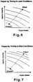
- the basic target injection timing value for lean operation is provided by the injection timing map illustrated in Figure 6 .
- the injection timing map of Figure 6 is a first lean target injection timing map that is configured to provide a lean target value corresponding to lean operation.
- Steps S42 to S47 of the control unit 20 constitutes a part of a fuel injection timing adjustment section that is configured to adjust the fuel injection timing to obtain an adjusted fuel injection timing based on the actual excess air ratio that was computed when an amount of adjustment in the target excess air ratio is larger than a prescribed value.
- the control unit 20 checks the status of the L-R flag to determine if rich spike control is in progress. If the L-R flag is 0, then the engine 1 is in a normal lean operating state and the control unit 20 skips step S43 and proceeds to step S47, where it outputs the basic target injection timing value ITL for lean operation.
- step S42 the control unit 20 determines if the amount of adjustment in the target excess air ratio is larger than a prescribed value, e.g., a sudden change in the excess air ratio ⁇ of approximately 0.8.
- a prescribed value e.g., a sudden change in the excess air ratio ⁇ of approximately 0.8.
- the value of the L-R flag is set to 1, because the excess air ratio ⁇ suddenly decreases from a lean value of between 2 and 3, for example, to a rich value of approximately 0.8.
- step S43 the control unit 20 sets a basic target injection timing value ITR for rich operation based on the engine operating state.
- the basic target injection timing value ITR for rich operation is set using the map of Figure 7 in the same manner as when the basic target injection timing value ITL is set for lean operation.
- the injection timing map of the Figure 7 is a second rich target injection timing map that is configured to provide a rich target value corresponding to the engine operating condition for rich operation.
- the basic target injection timing value ITR used for rich operation is more advanced than the basic target fuel injection timing value ITL used for lean operation.
- the lean operation and rich operation maps are configured such that the injection timing is more advanced during rich operation than during lean operation in order to improve the ignitability.
- step S44 the control unit 20 reads in the current actual excess air ratio ⁇ r and the target excess air ratio ⁇ t values for both before and after the excess air ratio ⁇ changes.
- each target value is obtained by searching a pre-stored map ( Figures 8 and 9 ) that gives the target excess air ratios ⁇ t based on the engine operating condition or state (similarly to the manner in which the basic injection timing is found using a map).
- Figure 8 illustrates a first lean target excess air ratio map configured to provide a lean target value corresponding to the engine operating condition for lean operation
- Figure 9 illustrates a second rich target excess air ratio map configured to provide a rich target value corresponding to the engine operation condition for rich operation.
- the actual excess air ratio ⁇ r is either detected using a fuel air ratio sensor 24 or computed based on such factors as the intake air quantity and the fuel injection quantity of the engine 1.
- control unit 20 finds the excess air ratio deviation R_Lambda based on the rich and lean target excess air ratios ⁇ t and the actual excess air ratio ⁇ r obtained in step S44 and calculates the fuel injection timing command value IT using the excess air ratio deviation R_Lambda and the basic target fuel injection timings values ITL and ITR.
- the excess air ratio deviation R_Lambda is found as a ratio of La with respect to L1 and L2, where the term La is the actual excess air ratio ⁇ r and the terms L1 and L2 are the lean target excess air ratio ⁇ t and the rich target excess air ratio ⁇ t, respectively.
- the fuel injection timing command value IT can be changed according to the change in the actual excess air ratio ⁇ r during the period when the actual excess air ratio ⁇ r is undergoing a large change from the lean target value to the rich target value.
- the fuel injection timing can be set appropriately with respect to the response delay of the actual excess air ratio ⁇ r caused by the intake air transport delay that occurs when the target excess air ratio ⁇ t value changes.
- the sudden changes in the fuel injection timing can be suppressed and torque fluctuations can be alleviated.
- the embodiments described heretofore are examples of revising the fuel injection timing in accordance with the change in the excess air ratio that occurs when rich spike control is executed for the purpose of regenerating a NOx trapping catalytic converter.
- the present teaching is not limited to such examples and can be applied effectively to basically any situation involving an operating state in which the excess air ratio changes rapidly, e.g., an operating state in which the exhaust gas is controlled to a high temperature in order to regenerate a DPF.
Landscapes
- Engineering & Computer Science (AREA)
- Chemical & Material Sciences (AREA)
- Combustion & Propulsion (AREA)
- Mechanical Engineering (AREA)
- General Engineering & Computer Science (AREA)
- Electrical Control Of Air Or Fuel Supplied To Internal-Combustion Engine (AREA)
- Exhaust Gas After Treatment (AREA)
- Processes For Solid Components From Exhaust (AREA)
Claims (8)
- Appareil de commande d'injection de carburant de moteur pour moteur (1), comprenant :une section de commande du rapport d'excédent d'air configurée pour commander un rapport d'excédent d'air (λ) vers un rapport d'excédent d'air cible (λt) qui est déterminé sur la base d'un état de fonctionnement de moteur du moteur (1) ;une section de commande du calage d'injection de carburant configurée pour commander un calage d'injection de carburant (IT) vers un calage d'injection de carburant cible qui est déterminé sur la base de l'état de fonctionnement du moteur ;une section de calcul du rapport d'excédent d'air réel configurée pour calculer un rapport d'excédent d'air réel (λr) du moteur (1) ; etune section d'ajustement du calage d'injection de carburant configurée pour ajuster le calage d'injection de carburant (IT) pour obtenir un calage d'injection de carburant ajusté sur la base du rapport d'excédent d'air cible (λt) et du rapport d'excédent d'air réel (λr),caractérisé en ce quela section d'ajustement du calage d'injection de carburant est configurée pour ajuster le calage d'injection de carburant (IT) pour obtenir le calage d'injection de carburant ajusté sur la base du rapport d'excédent d'air réel (λr) qui a été calculé lorsqu'une quantité d'ajustement du rapport d'excédent d'air cible (λt) est supérieure à une valeur prescrite, dans lequel la section d'ajustement du calage d'injection de carburant est configurée pour ajuster le calage d'injection de carburant (IT) par interpolation en fonction d'un rapport (R_Lambda) entre, d'une part, une différence entre le rapport d'excédent d'air cible (λt) en vigueur avant l'ajustement du rapport d'excédent d'air cible (λt) et le rapport d'excédent d'air cible (λt) qui sera appliqué après l'ajustement du rapport d'excédent d'air cible (λt) et, d'autre part, une différence entre le rapport d'excédent d'air réel (λr) et le rapport d'excédent d'air cible (λt) qui sera appliqué après l'ajustement du rapport d'excédent d'air cible (λt).
- Appareil de commande d'injection de carburant de moteur selon la revendication 1, caractérisé en ce que la section de commande du rapport d'excédent d'air est configurée pour détecter une quantité d'injection de carburant (Qf) et une vitesse de rotation du moteur (Ne) en tant qu'état de fonctionnement du moteur, et pour fixer le rapport d'excédent d'air cible (λt) en utilisant une carte configurée pour fournir le rapport d'excédent d'air cible (λt) correspondant à la quantité d'injection de carburant (Qf) et à la vitesse de rotation du moteur (Ne) qui ont été détectées.
- Appareil de commande d'injection de carburant de moteur selon la revendication 1 ou 2, caractérisé en ce que la section d'ajustement du calage d'injection de carburant est configurée pour ajuster le calage d'injection de carburant (IT) lorsqu'une commande de pic riche est exécutée pour régénérer un convertisseur catalytique (12) piégeant les NOx prévu dans un système d'échappement du moteur.
- Appareil de commande d'injection de carburant de moteur selon l'une quelconque des revendications 1 à 3, caractérisé en ce que la section d'ajustement du calage d'injection de carburant est configurée pour ajuster le calage d'injection de carburant (IT) lorsqu'une commande augmentant la température des gaz d'échappement est exécutée pour la régénération d'un filtre à particules fines de gaz d'échappement (13) prévu dans un système d'échappement du moteur.
- Appareil de commande d'injection de carburant de moteur selon la revendication 1 ou 2, caractérisé en ce que la section de commande du rapport d'excédent d'air est configurée pour commander le rapport d'excédent d'air (λ) en réglant un degré d'ouverture d'un papillon des gaz (8) installé dans un passage d'admission d'air (5) pour régler une quantité d'air d'admission (Qa).
- Appareil de commande d'injection de carburant de moteur selon la revendication 1, caractérisé en ce que la section de commande d'excédent d'air est configurée pour commander le rapport d'excédent d'air (λ) en utilisant une première carte de rapport d'excédent d'air configurée pour fournir une valeur cible pauvre correspondant à l'état de fonctionnement à mélange pauvre du moteur, et en utilisant une seconde carte de rapport d'excédent d'air configurée pour fournir une valeur cible riche correspondant à l'état de fonctionnement à mélange riche du moteur.
- Appareil de commande d'injection de carburant de moteur selon la revendication 1 ou 6, caractérisé en ce que la section de commande du calage d'injection de carburant est configurée pour commander le calage d'injection de carburant (IT) en utilisant une première carte de calage d'injection pour fournir une valeur cible pauvre correspondant à un fonctionnement à mélange pauvre, et en utilisant une seconde carte de calage d'injection configurée pour fournir une valeur cible riche correspondant à l'état de fonctionnement à mélange riche du moteur.
- Appareil de commande d'injection de carburant de moteur selon la revendication 1, caractérisé en ce que la section de commande du calage d'injection de carburant est configurée pour fixer le calage d'injection de carburant (IT) et la quantité d'injection de carburant (Qf) du carburant en fonction d'instants d'ouverture des soupapes injectrices et d'une durée d'ouverture des soupapes injectrices de carburant.
Applications Claiming Priority (2)
| Application Number | Priority Date | Filing Date | Title |
|---|---|---|---|
| JP2003283787 | 2003-07-31 | ||
| JP2003283787A JP4466008B2 (ja) | 2003-07-31 | 2003-07-31 | エンジンの燃料噴射制御装置 |
Publications (2)
| Publication Number | Publication Date |
|---|---|
| EP1503067A1 EP1503067A1 (fr) | 2005-02-02 |
| EP1503067B1 true EP1503067B1 (fr) | 2017-07-05 |
Family
ID=33535707
Family Applications (1)
| Application Number | Title | Priority Date | Filing Date |
|---|---|---|---|
| EP04016433.7A Expired - Lifetime EP1503067B1 (fr) | 2003-07-31 | 2004-07-13 | Appareil de commande d'injection pour moteur à combustion interne |
Country Status (4)
| Country | Link |
|---|---|
| US (1) | US7159389B2 (fr) |
| EP (1) | EP1503067B1 (fr) |
| JP (1) | JP4466008B2 (fr) |
| CN (1) | CN100368669C (fr) |
Families Citing this family (24)
| Publication number | Priority date | Publication date | Assignee | Title |
|---|---|---|---|---|
| JP3948437B2 (ja) * | 2003-06-23 | 2007-07-25 | いすゞ自動車株式会社 | 排気ガス浄化方法及び排気ガス浄化システム |
| US7239954B2 (en) * | 2004-09-17 | 2007-07-03 | Southwest Research Institute | Method for rapid, stable torque transition between lean rich combustion modes |
| JP4470771B2 (ja) * | 2005-03-18 | 2010-06-02 | トヨタ自動車株式会社 | 内燃機関の制御装置 |
| CN100432406C (zh) * | 2005-06-22 | 2008-11-12 | 株式会社电装 | 内燃机的燃料喷射控制设备 |
| JP4484772B2 (ja) * | 2005-06-23 | 2010-06-16 | 日立オートモティブシステムズ株式会社 | 内燃機関の失火検出装置 |
| JP4483794B2 (ja) | 2006-01-30 | 2010-06-16 | 株式会社デンソー | 圧縮着火式内燃機関の制御装置 |
| JP4049193B2 (ja) * | 2006-06-13 | 2008-02-20 | いすゞ自動車株式会社 | 排気ガス浄化システムの制御方法及び排気ガス浄化システム |
| DE102007041227B8 (de) * | 2006-09-05 | 2014-01-23 | GM Global Technology Operations LLC (n. d. Ges. d. Staates Delaware) | System zum Steuern der Regeneration von Mager-NOx-Fallen |
| US7895827B2 (en) * | 2006-09-28 | 2011-03-01 | GM Global Technology Operations LLC | Method and apparatus for controlling engine operation during regeneration of an exhaust aftertreatment system |
| US7788901B2 (en) * | 2007-02-19 | 2010-09-07 | Southwest Research Institute | Apparatus and method for regenerating exhaust treatment devices |
| JP4776566B2 (ja) * | 2007-02-28 | 2011-09-21 | 本田技研工業株式会社 | 内燃機関の燃料制御装置 |
| JP4743551B2 (ja) * | 2008-04-28 | 2011-08-10 | 株式会社デンソー | 内燃機関の制御装置 |
| US20100318276A1 (en) * | 2009-06-10 | 2010-12-16 | Zhengbai Liu | Control Strategy For A Diesel Engine During Lean-Rich Modulation |
| JP4858728B2 (ja) * | 2009-09-11 | 2012-01-18 | 三菱自動車工業株式会社 | 内燃機関の制御装置 |
| US8863728B2 (en) | 2010-08-17 | 2014-10-21 | GM Global Technology Operations LLC | Model-based transient fuel injection timing control methodology |
| US8527186B2 (en) * | 2010-09-08 | 2013-09-03 | Clean Air Power, Inc. | Method and apparatus for adaptive feedback control of an excess air ratio in a compression ignition natural gas engine |
| JP5548114B2 (ja) * | 2010-12-24 | 2014-07-16 | 川崎重工業株式会社 | 内燃機関の空燃比制御装置及び空燃比制御方法 |
| US9371763B2 (en) * | 2011-03-21 | 2016-06-21 | GM Global Technology Operations LLC | Method of operating an exhaust gas treatment system to prevent quenching during regeneration |
| RU2636600C1 (ru) | 2013-12-20 | 2017-11-24 | Тойота Дзидося Кабусики Кайся | Устройство управления выхлопными газами для двигателя внутреннего сгорания |
| JP6462311B2 (ja) | 2014-10-24 | 2019-01-30 | 日立オートモティブシステムズ株式会社 | エンジンの制御装置 |
| CN106150819B (zh) * | 2015-04-01 | 2018-07-17 | 光阳工业股份有限公司 | 引擎喷射阀的消音装置 |
| CN104912679A (zh) * | 2015-05-08 | 2015-09-16 | 潍柴动力股份有限公司 | 一种发动机尾气处理方法及装置 |
| US10174696B2 (en) * | 2016-12-27 | 2019-01-08 | Toyota Jidosha Kabushiki Kaisha | Control apparatus for internal combustion engine |
| CN119163518B (zh) * | 2024-11-22 | 2025-03-11 | 浙江吉利控股集团有限公司 | 车辆的控制方法、控制装置和车辆 |
Family Cites Families (12)
| Publication number | Priority date | Publication date | Assignee | Title |
|---|---|---|---|---|
| US6289672B1 (en) * | 1998-07-21 | 2001-09-18 | Toyota Jidosha Kabushiki Kaisha | Exhaust gas purification device for an internal combustion engine |
| JP2000087809A (ja) | 1998-09-09 | 2000-03-28 | Mazda Motor Corp | ディーゼルエンジンの制御装置 |
| JP3607980B2 (ja) * | 1999-12-16 | 2005-01-05 | トヨタ自動車株式会社 | 内燃機関 |
| DE10030936A1 (de) | 2000-06-24 | 2002-01-03 | Bosch Gmbh Robert | Verfahren zum Betreiben einer Brennkraftmaschine insbesondere eines Kraftfahrzeugs |
| JP3607984B2 (ja) * | 2000-06-26 | 2005-01-05 | トヨタ自動車株式会社 | 車載用内燃機関の排気浄化装置 |
| MY138476A (en) * | 2001-02-01 | 2009-06-30 | Honda Motor Co Ltd | Apparatus for and method of controlling plant |
| EP1245815B1 (fr) * | 2001-03-30 | 2006-06-07 | Mazda Motor Corporation | Moteur turbocompressé à allumage par étincelle et injection directe , méthode de commande, support de stockage lisible par ordinateur à cette fin. |
| JP3861621B2 (ja) * | 2001-05-30 | 2006-12-20 | 日産自動車株式会社 | ディーゼルエンジンの燃料噴射制御装置 |
| US6421599B1 (en) * | 2001-08-09 | 2002-07-16 | Ford Global Technologies, Inc. | Control strategy for an internal combustion engine in a hybrid vehicle |
| JP3864754B2 (ja) | 2001-10-25 | 2007-01-10 | 日産自動車株式会社 | 内燃機関の制御装置 |
| DE10234849A1 (de) | 2002-07-31 | 2004-02-19 | Robert Bosch Gmbh | Verfahren, Computerprogramm und Steuer- und/oder Regelgerät zum Betreiben einer Brennkraftmaschine, sowie Brennkraftmaschine |
| JP4096834B2 (ja) * | 2003-07-30 | 2008-06-04 | 日産自動車株式会社 | エンジンの燃料噴射制御装置 |
-
2003
- 2003-07-31 JP JP2003283787A patent/JP4466008B2/ja not_active Expired - Lifetime
-
2004
- 2004-07-06 US US10/883,679 patent/US7159389B2/en not_active Expired - Lifetime
- 2004-07-13 EP EP04016433.7A patent/EP1503067B1/fr not_active Expired - Lifetime
- 2004-07-30 CN CNB2004100587746A patent/CN100368669C/zh not_active Expired - Lifetime
Non-Patent Citations (1)
| Title |
|---|
| None * |
Also Published As
| Publication number | Publication date |
|---|---|
| JP2005048724A (ja) | 2005-02-24 |
| CN100368669C (zh) | 2008-02-13 |
| US20050022517A1 (en) | 2005-02-03 |
| CN1580528A (zh) | 2005-02-16 |
| JP4466008B2 (ja) | 2010-05-26 |
| EP1503067A1 (fr) | 2005-02-02 |
| US7159389B2 (en) | 2007-01-09 |
Similar Documents
| Publication | Publication Date | Title |
|---|---|---|
| US7159389B2 (en) | Engine fuel injection control apparatus | |
| EP1503065B1 (fr) | Dispositif de purification des gaz d'échappement | |
| US6957642B2 (en) | Exhaust gas recirculation control system | |
| US7062907B2 (en) | Regeneration control system | |
| US6993901B2 (en) | Excess air factor control of diesel engine | |
| US7299625B2 (en) | Exhaust purifying apparatus and exhaust purifying method for internal combustion engine | |
| EP1505283B1 (fr) | Dispositif de contrôle pour un moteur | |
| US7043900B2 (en) | Turbocharged engine control system | |
| US7247190B2 (en) | Engine exhaust gas cleaning apparatus | |
| US20040206070A1 (en) | Exhaust gas purifying system for internal combustion engine | |
| JP5195287B2 (ja) | 内燃機関の排気浄化装置 | |
| EP1965059B1 (fr) | Contrôle de post-injection de carburant d'un moteur à combustion interne | |
| US6907858B2 (en) | Engine fuel injection control system | |
| EP1503053A1 (fr) | Dispositif d' épuration de gaz d' échappement pour moteurs à combustion interne | |
| JP4857957B2 (ja) | エンジンの制御装置 | |
| JP5125298B2 (ja) | 内燃機関の燃料供給制御装置 | |
| JP4075822B2 (ja) | ディーゼル機関の排気浄化装置 | |
| JP2004245046A (ja) | 内燃機関の排気浄化装置 | |
| JP2006177425A (ja) | 希薄燃焼内燃機関の制御装置 | |
| JP4609061B2 (ja) | 内燃機関の制御装置 | |
| JP2003286882A (ja) | 内燃機関の制御装置 |
Legal Events
| Date | Code | Title | Description |
|---|---|---|---|
| PUAI | Public reference made under article 153(3) epc to a published international application that has entered the european phase |
Free format text: ORIGINAL CODE: 0009012 |
|
| 17P | Request for examination filed |
Effective date: 20040713 |
|
| AK | Designated contracting states |
Kind code of ref document: A1 Designated state(s): AT BE BG CH CY CZ DE DK EE ES FI FR GB GR HU IE IT LI LU MC NL PL PT RO SE SI SK TR |
|
| AX | Request for extension of the european patent |
Extension state: AL HR LT LV MK |
|
| AKX | Designation fees paid |
Designated state(s): DE FR GB |
|
| 17Q | First examination report despatched |
Effective date: 20050816 |
|
| GRAP | Despatch of communication of intention to grant a patent |
Free format text: ORIGINAL CODE: EPIDOSNIGR1 |
|
| INTG | Intention to grant announced |
Effective date: 20170310 |
|
| GRAS | Grant fee paid |
Free format text: ORIGINAL CODE: EPIDOSNIGR3 |
|
| GRAA | (expected) grant |
Free format text: ORIGINAL CODE: 0009210 |
|
| AK | Designated contracting states |
Kind code of ref document: B1 Designated state(s): DE FR GB |
|
| REG | Reference to a national code |
Ref country code: GB Ref legal event code: FG4D |
|
| REG | Reference to a national code |
Ref country code: DE Ref legal event code: R096 Ref document number: 602004051482 Country of ref document: DE |
|
| REG | Reference to a national code |
Ref country code: FR Ref legal event code: PLFP Year of fee payment: 14 |
|
| REG | Reference to a national code |
Ref country code: DE Ref legal event code: R097 Ref document number: 602004051482 Country of ref document: DE |
|
| PLBE | No opposition filed within time limit |
Free format text: ORIGINAL CODE: 0009261 |
|
| STAA | Information on the status of an ep patent application or granted ep patent |
Free format text: STATUS: NO OPPOSITION FILED WITHIN TIME LIMIT |
|
| REG | Reference to a national code |
Ref country code: FR Ref legal event code: PLFP Year of fee payment: 15 |
|
| 26N | No opposition filed |
Effective date: 20180406 |
|
| PGFP | Annual fee paid to national office [announced via postgrant information from national office to epo] |
Ref country code: FR Payment date: 20230621 Year of fee payment: 20 |
|
| PGFP | Annual fee paid to national office [announced via postgrant information from national office to epo] |
Ref country code: GB Payment date: 20230620 Year of fee payment: 20 |
|
| PGFP | Annual fee paid to national office [announced via postgrant information from national office to epo] |
Ref country code: DE Payment date: 20230620 Year of fee payment: 20 |
|
| REG | Reference to a national code |
Ref country code: DE Ref legal event code: R071 Ref document number: 602004051482 Country of ref document: DE |
|
| REG | Reference to a national code |
Ref country code: GB Ref legal event code: PE20 Expiry date: 20240712 |
|
| PG25 | Lapsed in a contracting state [announced via postgrant information from national office to epo] |
Ref country code: GB Free format text: LAPSE BECAUSE OF EXPIRATION OF PROTECTION Effective date: 20240712 |
|
| PG25 | Lapsed in a contracting state [announced via postgrant information from national office to epo] |
Ref country code: GB Free format text: LAPSE BECAUSE OF EXPIRATION OF PROTECTION Effective date: 20240712 |