EP1503080A1 - Dispositif d'alimentation en poudre et procédé d'exercer ce dispositif - Google Patents
Dispositif d'alimentation en poudre et procédé d'exercer ce dispositif Download PDFInfo
- Publication number
- EP1503080A1 EP1503080A1 EP04016184A EP04016184A EP1503080A1 EP 1503080 A1 EP1503080 A1 EP 1503080A1 EP 04016184 A EP04016184 A EP 04016184A EP 04016184 A EP04016184 A EP 04016184A EP 1503080 A1 EP1503080 A1 EP 1503080A1
- Authority
- EP
- European Patent Office
- Prior art keywords
- powder
- medium
- peristaltic pump
- delivery device
- peristaltic
- Prior art date
- Legal status (The legal status is an assumption and is not a legal conclusion. Google has not performed a legal analysis and makes no representation as to the accuracy of the status listed.)
- Granted
Links
- 239000000843 powder Substances 0.000 title claims abstract description 75
- 238000000034 method Methods 0.000 title claims abstract description 8
- 230000002572 peristaltic effect Effects 0.000 claims abstract description 65
- 238000003825 pressing Methods 0.000 claims description 8
- 229940098458 powder spray Drugs 0.000 claims description 4
- 238000005086 pumping Methods 0.000 claims description 2
- 230000001737 promoting effect Effects 0.000 claims 1
- 238000011144 upstream manufacturing Methods 0.000 claims 1
- 238000000576 coating method Methods 0.000 description 9
- 239000011248 coating agent Substances 0.000 description 5
- 239000000463 material Substances 0.000 description 3
- 230000015572 biosynthetic process Effects 0.000 description 2
- 239000007788 liquid Substances 0.000 description 2
- 230000003137 locomotive effect Effects 0.000 description 2
- 238000004519 manufacturing process Methods 0.000 description 2
- 208000034656 Contusions Diseases 0.000 description 1
- 230000002411 adverse Effects 0.000 description 1
- 238000007664 blowing Methods 0.000 description 1
- 208000034526 bruise Diseases 0.000 description 1
- 238000004140 cleaning Methods 0.000 description 1
- 230000001419 dependent effect Effects 0.000 description 1
- 238000005516 engineering process Methods 0.000 description 1
- 239000012530 fluid Substances 0.000 description 1
- 239000000203 mixture Substances 0.000 description 1
- 230000000149 penetrating effect Effects 0.000 description 1
- 229920001296 polysiloxane Polymers 0.000 description 1
- 238000005204 segregation Methods 0.000 description 1
- 238000007873 sieving Methods 0.000 description 1
- 239000007787 solid Substances 0.000 description 1
- 125000006850 spacer group Chemical group 0.000 description 1
Images
Classifications
-
- B—PERFORMING OPERATIONS; TRANSPORTING
- B05—SPRAYING OR ATOMISING IN GENERAL; APPLYING FLUENT MATERIALS TO SURFACES, IN GENERAL
- B05B—SPRAYING APPARATUS; ATOMISING APPARATUS; NOZZLES
- B05B7/00—Spraying apparatus for discharge of liquids or other fluent materials from two or more sources, e.g. of liquid and air, of powder and gas
- B05B7/14—Spraying apparatus for discharge of liquids or other fluent materials from two or more sources, e.g. of liquid and air, of powder and gas designed for spraying particulate materials
- B05B7/1404—Arrangements for supplying particulate material
- B05B7/144—Arrangements for supplying particulate material the means for supplying particulate material comprising moving mechanical means
-
- F—MECHANICAL ENGINEERING; LIGHTING; HEATING; WEAPONS; BLASTING
- F04—POSITIVE - DISPLACEMENT MACHINES FOR LIQUIDS; PUMPS FOR LIQUIDS OR ELASTIC FLUIDS
- F04B—POSITIVE-DISPLACEMENT MACHINES FOR LIQUIDS; PUMPS
- F04B43/00—Machines, pumps, or pumping installations having flexible working members
- F04B43/0009—Special features
- F04B43/0054—Special features particularities of the flexible members
- F04B43/0072—Special features particularities of the flexible members of tubular flexible members
-
- F—MECHANICAL ENGINEERING; LIGHTING; HEATING; WEAPONS; BLASTING
- F04—POSITIVE - DISPLACEMENT MACHINES FOR LIQUIDS; PUMPS FOR LIQUIDS OR ELASTIC FLUIDS
- F04B—POSITIVE-DISPLACEMENT MACHINES FOR LIQUIDS; PUMPS
- F04B43/00—Machines, pumps, or pumping installations having flexible working members
- F04B43/08—Machines, pumps, or pumping installations having flexible working members having tubular flexible members
- F04B43/082—Machines, pumps, or pumping installations having flexible working members having tubular flexible members the tubular flexible member being pressed against a wall by a number of elements, each having an alternating movement in a direction perpendicular to the axes of the tubular member and each having its own driving mechanism
-
- F—MECHANICAL ENGINEERING; LIGHTING; HEATING; WEAPONS; BLASTING
- F04—POSITIVE - DISPLACEMENT MACHINES FOR LIQUIDS; PUMPS FOR LIQUIDS OR ELASTIC FLUIDS
- F04B—POSITIVE-DISPLACEMENT MACHINES FOR LIQUIDS; PUMPS
- F04B43/00—Machines, pumps, or pumping installations having flexible working members
- F04B43/12—Machines, pumps, or pumping installations having flexible working members having peristaltic action
- F04B43/1253—Machines, pumps, or pumping installations having flexible working members having peristaltic action by using two or more rollers as squeezing elements, the rollers moving on an arc of a circle during squeezing
Definitions
- the present invention relates to a powder conveyor. Further refers It is a process for operating this powder conveyor.
- the present powder conveyor is mainly for use intended in powder coating plants.
- these plants is colored powder by e.g. powder conveying units immersed in commercially available powder containers transported via lines to powder spray guns.
- the powder promotion is usually by means of injectors.
- Injector delivery has a number of disadvantages with himself. On the one hand results in a large air consumption and on the other hand a much too high powder speed. This has a Ansintern of the lines result.
- the powder also shoots past the workpiece. It results in a poor Umgriff and too much powder cloud.
- facilities with alternately fillable and emptied container-like metering chambers In any case, a reproducible, very accurate flow rate not possible.
- Sophisticated coatings such as metallic coatings, can therefore be hardly apply in consistent color and quality. Not least high wear costs arise at the injector and at the lines.
- the invention sets itself the task to provide a powder conveyor which is a powdered medium with definable volume, even and with the smallest possible Use of a gaseous medium promotes. Furthermore, a method for Operation of this powder conveyor can be specified.
- the inventive powder conveyor corresponds to the characterizing Features of claim 1.
- the method of operation This powder conveyor is shown in claim 15. Further advantageous embodiments of the inventive concept go from the dependent claims.
- the present powder conveyor can in powder coating systems the amount of air and powder are significantly reduced.
- Metallic coatings are also problem-free and in high surface quality possible.
- a color change brings no loss of powder with it.
- the closed system results in a dirt-free work.
- the powder output is uniform and reproducible, even with different Powder material.
- the powder cloud can also be used with cable lengths over 20 meters.
- the production capacity is increased, due to higher chain speed and much faster color change.
- the wear costs are low.
- the system is very user-friendly. The operation always remains the same, so too changing auxiliary personnel can be used.
- This support line will be initially formed by a supply line 2, which is technically known Way is to immerse in a powder container, especially in a commercial Powder container or in a likewise known powder fluid container. It is also possible to interpose a powder sieving device, for example, an ultrasonic sieve.
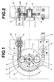
- Essential for the invention is the arrangement of a peristaltic pump 1, i.e. a peristaltic pump, for conveying the powdery medium.
- the supply line 2 opens into a conveyor line continuing, flexible peristaltic tube 3, for example a silicone tube.
- the peristaltic tube 3 then leads to a discharge line 4, to which a known powder spray gun can be connected.
- Peristaltic or peristaltic pumps are in themselves only for conveying of liquids usable. At most, the liquid may have a certain Contain solid content. In contrast, powdery media tend to in the peristaltic tube repeatedly squeezed during pumping 3. The promotion would be disturbed or even blocked. For this reason, were so far peristaltic pumps for the unusable for this purpose. In the inventive powder conveyor However, this problem is solved.
- Peristaltic pump 1 used.
- This has a rotation element 5, For example, a rotating about a rotation axis disc.
- At this Rotary element 5 is arranged at least one pressing element, the to press on the peristaltic tube 3 is determined. Preferably it is to two idler rollers 6 and 7, which are diametrically opposed are opposite.
- the conveying direction of the peristaltic pump. 1 corresponding rotational direction R of the rotary element 5 is shown in Fig. 1st indicated with an arrow.
- the peristaltic tube 3 is in a coaxial guided around the axis of rotation of the rotary element 5 pitch circle such, that it lies in the area of action of the rollers 6 and 7.
- each one of the rollers. 6 or 7 passes the peristaltic tube 3, this is between the respective Roller 6 or 7 and a circular or part-circular guide wall. 8 the peristaltic pump 1 squeezed. As a result, the internal cross section is at this point of the peristaltic tube 3 closed.
- the one in the sphere of influence the rollers 6 and 7 lying, part-circular portion 9 of the Peristaltic tube 3 extends over approximately 158 degrees of angle. Thereafter, the peristaltic tube 3 is preferably bent outwards, i.e. away from the turning circle of the rollers 6 and 7.
- an inlet 10 for a gaseous medium is provided, in particular Compressed air.
- the inlet 10 consists for example of a tubular Adapter with transverse bore and preferably has one Solenoid valve on.
- a closing device 11 is arranged, for example one with a lifting cylinder operable squeezing device 12.
- a second Inlet 13 is arranged in the conveying direction after the peristaltic pump 1 .
- the first inlet 10 can this also consist of a spacer with transverse bore.
- the intermediate piece can at the same time also the connection of the peristaltic tube 3 with the discharge line 4 serve.
- the second for example formed as a nozzle inlet 13 is also a gaseous Medium, injected in particular compressed air.
- the air supply through the inlet 13 can then be briefly reduced or be interrupted when the inlet 10 is briefly opened.
- locomotive movement of the peristaltic tube 3 is a certain amount of powdered Aspirated medium.
- the controller closes the closing device 11 and blows through the inlet 10, the gaseous medium.
- the locomotive Roller 6 or 7 has passed the end of section 9 opens the passage in the direction of discharge 4.
- the powdery Medium can escape in conveying or ejection direction. In this Moment already begins the second roll 6 or 7 the next bruise. This also makes the previously located powdery medium pushed in conveying direction.
- the closing device 11 is open again, the inlet 10 too.
- New powdery medium is sucked in. ever after the rotational speed of the rotary element 5, always get new powder portions at short intervals in the discharge line 4.
- the injected through the second inlet 13 gaseous medium, especially compressed air, causes a uniform emission of the mixture made of powder and gas.
- the flow volume can be adjusted continuously become.
- the powdered medium not - as previously u.a. was common - from a supply line in a special, alternately fillable and emptying dosing and from this in turn led to a discharge.
- the form Feed line 2, the peristaltic tube 3 and the discharge line 4 a continuous delivery line with approximately the same inner cross section. It is obvious that this is advantageous in terms of material handling. It is in rest noted that both the supply line 1 as well the discharge line 4 - like the peristaltic tube 3 - usually consist of a flexible hose. An exchange of these parts is thus neither time nor cost intensive.
- the powdery medium can be over a distance of at least Aspirate for 3 m and convey over a distance of not more than 40 m.
- the through this powder conveyor compared to the previous Injektor concept achieved values are very remarkable.
- the hose diameter can be 400% smaller, the powder speed 4x lower, the air consumption 10x lower and the material charge, i. the applied Amount of powder, higher.
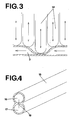
- the powder conveyor in detail also differently than previously described execute. So could the Peristaltic pump according to Fig. 3 theoretically linear, as a so-called finger pump be constructed, in the juxtaposed fingers 14, i.e. Pressing elements, one after the other in the conveying direction on the flexible Press peristaltic tube 3. Technically, these pressing elements the squeezing closure device 11 correspond.
- Fig. 3 illustrates at the same time generally the function of the peristaltic pump 1, with the squeezing point advancing in the conveying direction.
- a multi-channel peristaltic pump is also used, in the case of the same drive, several parallel peristaltic tubes 3 are applied. This can be done on the same drive shaft a plurality of rotary elements 5 with the respective rollers 6 and 7 be arranged.
- the work of the same peristaltic pump not only for conveying the powdery medium, but also for Promotion of the gaseous medium, i. Formation of the required compressed air to use.
- the peristaltic tube could 4 as a double tube 15, with two parallel extending chambers 16 and 17 may be formed.
Landscapes
- Engineering & Computer Science (AREA)
- Mechanical Engineering (AREA)
- General Engineering & Computer Science (AREA)
- Reciprocating Pumps (AREA)
- Air Transport Of Granular Materials (AREA)
- Control And Other Processes For Unpacking Of Materials (AREA)
- Relays Between Conveyors (AREA)
- Formation And Processing Of Food Products (AREA)
Applications Claiming Priority (2)
| Application Number | Priority Date | Filing Date | Title |
|---|---|---|---|
| CH13072003 | 2003-07-28 | ||
| CH01307/03A CH696276A5 (de) | 2003-07-28 | 2003-07-28 | Pulverfördereinrichtung und Verfahren zu deren Betrieb. |
Publications (2)
| Publication Number | Publication Date |
|---|---|
| EP1503080A1 true EP1503080A1 (fr) | 2005-02-02 |
| EP1503080B1 EP1503080B1 (fr) | 2006-02-22 |
Family
ID=33520359
Family Applications (1)
| Application Number | Title | Priority Date | Filing Date |
|---|---|---|---|
| EP04016184A Expired - Lifetime EP1503080B1 (fr) | 2003-07-28 | 2004-07-09 | Dispositif d'alimentation en poudre et procédé d'exercer ce dispositif |
Country Status (4)
| Country | Link |
|---|---|
| EP (1) | EP1503080B1 (fr) |
| AT (1) | ATE318373T1 (fr) |
| CH (1) | CH696276A5 (fr) |
| DE (1) | DE502004000304D1 (fr) |
Cited By (1)
| Publication number | Priority date | Publication date | Assignee | Title |
|---|---|---|---|---|
| DE202015102643U1 (de) | 2015-05-22 | 2015-08-19 | Dirk Brinkmeyer | Pulverbeschichtungseinrichtung |
Families Citing this family (1)
| Publication number | Priority date | Publication date | Assignee | Title |
|---|---|---|---|---|
| DE102022128182A1 (de) | 2022-10-25 | 2024-04-25 | EAR Ritterbach GmbH & Co. KG | Fördereinrichtung zur gerichteten Förderung pulverförmiger Stoffe sowie zugehöriges Verfahren |
Citations (3)
| Publication number | Priority date | Publication date | Assignee | Title |
|---|---|---|---|---|
| CH352547A (fr) * | 1959-01-16 | 1961-02-28 | Simon Ltd Henry | Dispositif impulseur |
| GB1383109A (en) * | 1972-07-13 | 1975-02-05 | British Insulated Callenders | Application of powder to elongate articles |
| US5924852A (en) * | 1996-03-12 | 1999-07-20 | Moubayed; Ahmad-Maher | Linear peristaltic pump |
-
2003
- 2003-07-28 CH CH01307/03A patent/CH696276A5/de not_active IP Right Cessation
-
2004
- 2004-07-09 DE DE502004000304T patent/DE502004000304D1/de not_active Expired - Lifetime
- 2004-07-09 AT AT04016184T patent/ATE318373T1/de not_active IP Right Cessation
- 2004-07-09 EP EP04016184A patent/EP1503080B1/fr not_active Expired - Lifetime
Patent Citations (3)
| Publication number | Priority date | Publication date | Assignee | Title |
|---|---|---|---|---|
| CH352547A (fr) * | 1959-01-16 | 1961-02-28 | Simon Ltd Henry | Dispositif impulseur |
| GB1383109A (en) * | 1972-07-13 | 1975-02-05 | British Insulated Callenders | Application of powder to elongate articles |
| US5924852A (en) * | 1996-03-12 | 1999-07-20 | Moubayed; Ahmad-Maher | Linear peristaltic pump |
Cited By (2)
| Publication number | Priority date | Publication date | Assignee | Title |
|---|---|---|---|---|
| DE202015102643U1 (de) | 2015-05-22 | 2015-08-19 | Dirk Brinkmeyer | Pulverbeschichtungseinrichtung |
| DE102016108473A1 (de) | 2015-05-22 | 2016-11-24 | Dirk Brinkmeyer | Pulverbeschichtungseinrichtung |
Also Published As
| Publication number | Publication date |
|---|---|
| DE502004000304D1 (de) | 2006-04-27 |
| CH696276A5 (de) | 2007-03-15 |
| EP1503080B1 (fr) | 2006-02-22 |
| ATE318373T1 (de) | 2006-03-15 |
Similar Documents
| Publication | Publication Date | Title |
|---|---|---|
| EP1427536B1 (fr) | Dispositif pour transporter de la poudre et procede pour le faire fonctionner | |
| EP1958899B1 (fr) | Dispositif d'alimentation de fluide | |
| EP2981365B1 (fr) | Pompe de transport de poudre en phase dense et procede de fonctionnement correspondant | |
| EP2279796A2 (fr) | Procédé et dispositif de transport de matériaux sous forme de poudre | |
| DE10300280A1 (de) | Pumpeneinrichtung für Pulver, Verfahren hierfür und Pulverbeschichtungseinrichtung | |
| DE2808183A1 (de) | Vorrichtungen fuer giessharzanlagen zum kontrollieren gleicher und/oder unterschiedlicher, auch synchronisierter ausstossmengen fliessfaehiger bis hochviskoser medien | |
| EP0061630A1 (fr) | Pompe à engrenage à dispositif pour nettoyer | |
| DE19728155A1 (de) | Verfahren und Vorrichtung zum Lackieren | |
| DE19709988A1 (de) | Lackiereinrichtung | |
| WO2017004634A1 (fr) | Dispositif pour produire un mélange composé d'au moins un gaz et d'au moins un composant plastique liquide | |
| DE3134101C2 (fr) | ||
| EP0692441B1 (fr) | Procédé et dispositf pour transport pneumatique de matériau en vrac | |
| EP1503080B1 (fr) | Dispositif d'alimentation en poudre et procédé d'exercer ce dispositif | |
| EP0564807B1 (fr) | Dispositif de transport et de dosage pour produits visqueux | |
| CH597513A5 (en) | Reciprocating pump for conveying viscous material | |
| EP1395490B1 (fr) | Dispositif de dosage installe dans une machine servant a remplir des tubes | |
| EP0627268B1 (fr) | Dispositif de pulvérisation de liquide, en particulier pour les machines à imprimer | |
| DE3840259A1 (de) | Schlauchpumpe | |
| EP0816266B1 (fr) | Procédé et dispositif pour remplir une conduite de transport en courant épais | |
| DE911805C (de) | Dosierpumpe | |
| CH616235A5 (en) | Device for testing fuel injection valves. | |
| DE10320550B4 (de) | Lackdosiereinrichtung | |
| DE3629028C2 (fr) | ||
| DE3624592A1 (de) | Dosiervorrichtung zum abfuellen von nahrungsmitteln, insbesondere von fluessigkeit aufweisenden produkten mit festen bzw. stueckigen bestandteilen | |
| DE102007011736A1 (de) | Förderanlage für ein Pulver |
Legal Events
| Date | Code | Title | Description |
|---|---|---|---|
| PUAI | Public reference made under article 153(3) epc to a published international application that has entered the european phase |
Free format text: ORIGINAL CODE: 0009012 |
|
| AK | Designated contracting states |
Kind code of ref document: A1 Designated state(s): AT BE BG CH CY CZ DE DK EE ES FI FR GB GR HU IE IT LI LU MC NL PL PT RO SE SI SK TR |
|
| AX | Request for extension of the european patent |
Extension state: AL HR LT LV MK |
|
| 17P | Request for examination filed |
Effective date: 20050526 |
|
| GRAP | Despatch of communication of intention to grant a patent |
Free format text: ORIGINAL CODE: EPIDOSNIGR1 |
|
| AKX | Designation fees paid |
Designated state(s): AT BE BG CH CY CZ DE DK EE ES FI FR GB GR HU IE IT LI LU MC NL PL PT RO SE SI SK TR |
|
| GRAS | Grant fee paid |
Free format text: ORIGINAL CODE: EPIDOSNIGR3 |
|
| GRAA | (expected) grant |
Free format text: ORIGINAL CODE: 0009210 |
|
| AK | Designated contracting states |
Kind code of ref document: B1 Designated state(s): AT BE BG CH CY CZ DE DK EE ES FI FR GB GR HU IE IT LI LU MC NL PL PT RO SE SI SK TR |
|
| PG25 | Lapsed in a contracting state [announced via postgrant information from national office to epo] |
Ref country code: FI Free format text: LAPSE BECAUSE OF FAILURE TO SUBMIT A TRANSLATION OF THE DESCRIPTION OR TO PAY THE FEE WITHIN THE PRESCRIBED TIME-LIMIT Effective date: 20060222 Ref country code: IT Free format text: LAPSE BECAUSE OF FAILURE TO SUBMIT A TRANSLATION OF THE DESCRIPTION OR TO PAY THE FEE WITHIN THE PRESCRIBED TIME-LIMIT;WARNING: LAPSES OF ITALIAN PATENTS WITH EFFECTIVE DATE BEFORE 2007 MAY HAVE OCCURRED AT ANY TIME BEFORE 2007. THE CORRECT EFFECTIVE DATE MAY BE DIFFERENT FROM THE ONE RECORDED. Effective date: 20060222 Ref country code: GB Free format text: LAPSE BECAUSE OF FAILURE TO SUBMIT A TRANSLATION OF THE DESCRIPTION OR TO PAY THE FEE WITHIN THE PRESCRIBED TIME-LIMIT Effective date: 20060222 Ref country code: RO Free format text: LAPSE BECAUSE OF FAILURE TO SUBMIT A TRANSLATION OF THE DESCRIPTION OR TO PAY THE FEE WITHIN THE PRESCRIBED TIME-LIMIT Effective date: 20060222 Ref country code: IE Free format text: LAPSE BECAUSE OF FAILURE TO SUBMIT A TRANSLATION OF THE DESCRIPTION OR TO PAY THE FEE WITHIN THE PRESCRIBED TIME-LIMIT Effective date: 20060222 Ref country code: PL Free format text: LAPSE BECAUSE OF FAILURE TO SUBMIT A TRANSLATION OF THE DESCRIPTION OR TO PAY THE FEE WITHIN THE PRESCRIBED TIME-LIMIT Effective date: 20060222 Ref country code: NL Free format text: LAPSE BECAUSE OF FAILURE TO SUBMIT A TRANSLATION OF THE DESCRIPTION OR TO PAY THE FEE WITHIN THE PRESCRIBED TIME-LIMIT Effective date: 20060222 Ref country code: SI Free format text: LAPSE BECAUSE OF FAILURE TO SUBMIT A TRANSLATION OF THE DESCRIPTION OR TO PAY THE FEE WITHIN THE PRESCRIBED TIME-LIMIT Effective date: 20060222 Ref country code: SK Free format text: LAPSE BECAUSE OF FAILURE TO SUBMIT A TRANSLATION OF THE DESCRIPTION OR TO PAY THE FEE WITHIN THE PRESCRIBED TIME-LIMIT Effective date: 20060222 |
|
| REG | Reference to a national code |
Ref country code: GB Ref legal event code: FG4D Free format text: NOT ENGLISH |
|
| REG | Reference to a national code |
Ref country code: CH Ref legal event code: EP |
|
| REG | Reference to a national code |
Ref country code: IE Ref legal event code: FG4D Free format text: LANGUAGE OF EP DOCUMENT: GERMAN |
|
| REF | Corresponds to: |
Ref document number: 502004000304 Country of ref document: DE Date of ref document: 20060427 Kind code of ref document: P |
|
| PG25 | Lapsed in a contracting state [announced via postgrant information from national office to epo] |
Ref country code: SE Free format text: LAPSE BECAUSE OF FAILURE TO SUBMIT A TRANSLATION OF THE DESCRIPTION OR TO PAY THE FEE WITHIN THE PRESCRIBED TIME-LIMIT Effective date: 20060522 Ref country code: BG Free format text: LAPSE BECAUSE OF FAILURE TO SUBMIT A TRANSLATION OF THE DESCRIPTION OR TO PAY THE FEE WITHIN THE PRESCRIBED TIME-LIMIT Effective date: 20060522 Ref country code: DK Free format text: LAPSE BECAUSE OF FAILURE TO SUBMIT A TRANSLATION OF THE DESCRIPTION OR TO PAY THE FEE WITHIN THE PRESCRIBED TIME-LIMIT Effective date: 20060522 |
|
| PG25 | Lapsed in a contracting state [announced via postgrant information from national office to epo] |
Ref country code: ES Free format text: LAPSE BECAUSE OF FAILURE TO SUBMIT A TRANSLATION OF THE DESCRIPTION OR TO PAY THE FEE WITHIN THE PRESCRIBED TIME-LIMIT Effective date: 20060602 |
|
| PG25 | Lapsed in a contracting state [announced via postgrant information from national office to epo] |
Ref country code: PT Free format text: LAPSE BECAUSE OF FAILURE TO SUBMIT A TRANSLATION OF THE DESCRIPTION OR TO PAY THE FEE WITHIN THE PRESCRIBED TIME-LIMIT Effective date: 20060724 |
|
| PG25 | Lapsed in a contracting state [announced via postgrant information from national office to epo] |
Ref country code: BE Free format text: LAPSE BECAUSE OF NON-PAYMENT OF DUE FEES Effective date: 20060731 Ref country code: MC Free format text: LAPSE BECAUSE OF NON-PAYMENT OF DUE FEES Effective date: 20060731 |
|
| NLV1 | Nl: lapsed or annulled due to failure to fulfill the requirements of art. 29p and 29m of the patents act | ||
| GBV | Gb: ep patent (uk) treated as always having been void in accordance with gb section 77(7)/1977 [no translation filed] |
Effective date: 20060222 |
|
| REG | Reference to a national code |
Ref country code: IE Ref legal event code: FD4D |
|
| PLBE | No opposition filed within time limit |
Free format text: ORIGINAL CODE: 0009261 |
|
| STAA | Information on the status of an ep patent application or granted ep patent |
Free format text: STATUS: NO OPPOSITION FILED WITHIN TIME LIMIT |
|
| 26N | No opposition filed |
Effective date: 20061123 |
|
| EN | Fr: translation not filed | ||
| REG | Reference to a national code |
Ref country code: CH Ref legal event code: NV Representative=s name: PA ALDO ROEMPLER |
|
| PG25 | Lapsed in a contracting state [announced via postgrant information from national office to epo] |
Ref country code: AT Free format text: LAPSE BECAUSE OF NON-PAYMENT OF DUE FEES Effective date: 20060709 |
|
| BERE | Be: lapsed |
Owner name: MS-OBERFLACHENTECHNIK A.G. Effective date: 20060731 |
|
| PG25 | Lapsed in a contracting state [announced via postgrant information from national office to epo] |
Ref country code: FR Free format text: LAPSE BECAUSE OF FAILURE TO SUBMIT A TRANSLATION OF THE DESCRIPTION OR TO PAY THE FEE WITHIN THE PRESCRIBED TIME-LIMIT Effective date: 20070420 Ref country code: CZ Free format text: LAPSE BECAUSE OF FAILURE TO SUBMIT A TRANSLATION OF THE DESCRIPTION OR TO PAY THE FEE WITHIN THE PRESCRIBED TIME-LIMIT Effective date: 20060222 Ref country code: GR Free format text: LAPSE BECAUSE OF FAILURE TO SUBMIT A TRANSLATION OF THE DESCRIPTION OR TO PAY THE FEE WITHIN THE PRESCRIBED TIME-LIMIT Effective date: 20060523 |
|
| PG25 | Lapsed in a contracting state [announced via postgrant information from national office to epo] |
Ref country code: EE Free format text: LAPSE BECAUSE OF FAILURE TO SUBMIT A TRANSLATION OF THE DESCRIPTION OR TO PAY THE FEE WITHIN THE PRESCRIBED TIME-LIMIT Effective date: 20060222 |
|
| PG25 | Lapsed in a contracting state [announced via postgrant information from national office to epo] |
Ref country code: TR Free format text: LAPSE BECAUSE OF FAILURE TO SUBMIT A TRANSLATION OF THE DESCRIPTION OR TO PAY THE FEE WITHIN THE PRESCRIBED TIME-LIMIT Effective date: 20060222 Ref country code: HU Free format text: LAPSE BECAUSE OF FAILURE TO SUBMIT A TRANSLATION OF THE DESCRIPTION OR TO PAY THE FEE WITHIN THE PRESCRIBED TIME-LIMIT Effective date: 20060823 Ref country code: LU Free format text: LAPSE BECAUSE OF NON-PAYMENT OF DUE FEES Effective date: 20060709 |
|
| REG | Reference to a national code |
Ref country code: CH Ref legal event code: PCAR Free format text: ALDO ROEMPLER PATENTANWALT;BRENDENWEG 11 POSTFACH 154;9424 RHEINECK (CH) |
|
| PG25 | Lapsed in a contracting state [announced via postgrant information from national office to epo] |
Ref country code: FR Free format text: LAPSE BECAUSE OF FAILURE TO SUBMIT A TRANSLATION OF THE DESCRIPTION OR TO PAY THE FEE WITHIN THE PRESCRIBED TIME-LIMIT Effective date: 20060222 Ref country code: CY Free format text: LAPSE BECAUSE OF FAILURE TO SUBMIT A TRANSLATION OF THE DESCRIPTION OR TO PAY THE FEE WITHIN THE PRESCRIBED TIME-LIMIT Effective date: 20060222 |
|
| PGFP | Annual fee paid to national office [announced via postgrant information from national office to epo] |
Ref country code: CH Payment date: 20100909 Year of fee payment: 7 |
|
| PGFP | Annual fee paid to national office [announced via postgrant information from national office to epo] |
Ref country code: DE Payment date: 20100823 Year of fee payment: 7 |
|
| REG | Reference to a national code |
Ref country code: CH Ref legal event code: PL |
|
| PG25 | Lapsed in a contracting state [announced via postgrant information from national office to epo] |
Ref country code: CH Free format text: LAPSE BECAUSE OF NON-PAYMENT OF DUE FEES Effective date: 20110731 Ref country code: LI Free format text: LAPSE BECAUSE OF NON-PAYMENT OF DUE FEES Effective date: 20110731 Ref country code: DE Free format text: LAPSE BECAUSE OF NON-PAYMENT OF DUE FEES Effective date: 20120201 |
|
| REG | Reference to a national code |
Ref country code: DE Ref legal event code: R119 Ref document number: 502004000304 Country of ref document: DE Effective date: 20120201 |