EP1503089A1 - Méthode d'assemblage de pièces accessibles d'un seul côté et dispositif de mise en oeuvre de la méthode - Google Patents
Méthode d'assemblage de pièces accessibles d'un seul côté et dispositif de mise en oeuvre de la méthode Download PDFInfo
- Publication number
- EP1503089A1 EP1503089A1 EP03090235A EP03090235A EP1503089A1 EP 1503089 A1 EP1503089 A1 EP 1503089A1 EP 03090235 A EP03090235 A EP 03090235A EP 03090235 A EP03090235 A EP 03090235A EP 1503089 A1 EP1503089 A1 EP 1503089A1
- Authority
- EP
- European Patent Office
- Prior art keywords
- mandrel
- rivet
- blind rivet
- blind
- head
- Prior art date
- Legal status (The legal status is an assumption and is not a legal conclusion. Google has not performed a legal analysis and makes no representation as to the accuracy of the status listed.)
- Granted
Links
Images









Classifications
-
- B—PERFORMING OPERATIONS; TRANSPORTING
- B21—MECHANICAL METAL-WORKING WITHOUT ESSENTIALLY REMOVING MATERIAL; PUNCHING METAL
- B21J—FORGING; HAMMERING; PRESSING METAL; RIVETING; FORGE FURNACES
- B21J15/00—Riveting
- B21J15/02—Riveting procedures
-
- B—PERFORMING OPERATIONS; TRANSPORTING
- B21—MECHANICAL METAL-WORKING WITHOUT ESSENTIALLY REMOVING MATERIAL; PUNCHING METAL
- B21J—FORGING; HAMMERING; PRESSING METAL; RIVETING; FORGE FURNACES
- B21J15/00—Riveting
- B21J15/02—Riveting procedures
- B21J15/025—Setting self-piercing rivets
-
- B—PERFORMING OPERATIONS; TRANSPORTING
- B21—MECHANICAL METAL-WORKING WITHOUT ESSENTIALLY REMOVING MATERIAL; PUNCHING METAL
- B21J—FORGING; HAMMERING; PRESSING METAL; RIVETING; FORGE FURNACES
- B21J15/00—Riveting
- B21J15/02—Riveting procedures
- B21J15/027—Setting rivets by friction heating
-
- B—PERFORMING OPERATIONS; TRANSPORTING
- B21—MECHANICAL METAL-WORKING WITHOUT ESSENTIALLY REMOVING MATERIAL; PUNCHING METAL
- B21J—FORGING; HAMMERING; PRESSING METAL; RIVETING; FORGE FURNACES
- B21J15/00—Riveting
- B21J15/02—Riveting procedures
- B21J15/04—Riveting hollow rivets mechanically
-
- B—PERFORMING OPERATIONS; TRANSPORTING
- B21—MECHANICAL METAL-WORKING WITHOUT ESSENTIALLY REMOVING MATERIAL; PUNCHING METAL
- B21J—FORGING; HAMMERING; PRESSING METAL; RIVETING; FORGE FURNACES
- B21J15/00—Riveting
- B21J15/02—Riveting procedures
- B21J15/04—Riveting hollow rivets mechanically
- B21J15/043—Riveting hollow rivets mechanically by pulling a mandrel
-
- B—PERFORMING OPERATIONS; TRANSPORTING
- B21—MECHANICAL METAL-WORKING WITHOUT ESSENTIALLY REMOVING MATERIAL; PUNCHING METAL
- B21J—FORGING; HAMMERING; PRESSING METAL; RIVETING; FORGE FURNACES
- B21J15/00—Riveting
- B21J15/02—Riveting procedures
- B21J15/04—Riveting hollow rivets mechanically
- B21J15/048—Setting self-drilling hollow rivets
-
- B—PERFORMING OPERATIONS; TRANSPORTING
- B21—MECHANICAL METAL-WORKING WITHOUT ESSENTIALLY REMOVING MATERIAL; PUNCHING METAL
- B21J—FORGING; HAMMERING; PRESSING METAL; RIVETING; FORGE FURNACES
- B21J15/00—Riveting
- B21J15/02—Riveting procedures
- B21J15/08—Riveting by applying heat, e.g. to the end parts of the rivets to enable heads to be formed
-
- B—PERFORMING OPERATIONS; TRANSPORTING
- B23—MACHINE TOOLS; METAL-WORKING NOT OTHERWISE PROVIDED FOR
- B23K—SOLDERING OR UNSOLDERING; WELDING; CLADDING OR PLATING BY SOLDERING OR WELDING; CUTTING BY APPLYING HEAT LOCALLY, e.g. FLAME CUTTING; WORKING BY LASER BEAM
- B23K20/00—Non-electric welding by applying impact or other pressure, with or without the application of heat, e.g. cladding or plating
- B23K20/12—Non-electric welding by applying impact or other pressure, with or without the application of heat, e.g. cladding or plating the heat being generated by friction; Friction welding
- B23K20/129—Non-electric welding by applying impact or other pressure, with or without the application of heat, e.g. cladding or plating the heat being generated by friction; Friction welding specially adapted for particular articles or work
-
- F—MECHANICAL ENGINEERING; LIGHTING; HEATING; WEAPONS; BLASTING
- F16—ENGINEERING ELEMENTS AND UNITS; GENERAL MEASURES FOR PRODUCING AND MAINTAINING EFFECTIVE FUNCTIONING OF MACHINES OR INSTALLATIONS; THERMAL INSULATION IN GENERAL
- F16B—DEVICES FOR FASTENING OR SECURING CONSTRUCTIONAL ELEMENTS OR MACHINE PARTS TOGETHER, e.g. NAILS, BOLTS, CIRCLIPS, CLAMPS, CLIPS OR WEDGES; JOINTS OR JOINTING
- F16B19/00—Bolts without screw-thread; Pins, including deformable elements; Rivets
- F16B19/04—Rivets; Spigots or the like fastened by riveting
- F16B19/08—Hollow rivets; Multi-part rivets
- F16B19/10—Hollow rivets; Multi-part rivets fastened by expanding mechanically
- F16B19/1027—Multi-part rivets
- F16B19/1036—Blind rivets
- F16B19/1045—Blind rivets fastened by a pull - mandrel or the like
- F16B19/1072—Blind rivets fastened by a pull - mandrel or the like the pull-mandrel or the like comprising a thread and being rotated with respect to the rivet, thereby mechanically expanding and fastening the rivet
-
- F—MECHANICAL ENGINEERING; LIGHTING; HEATING; WEAPONS; BLASTING
- F16—ENGINEERING ELEMENTS AND UNITS; GENERAL MEASURES FOR PRODUCING AND MAINTAINING EFFECTIVE FUNCTIONING OF MACHINES OR INSTALLATIONS; THERMAL INSULATION IN GENERAL
- F16B—DEVICES FOR FASTENING OR SECURING CONSTRUCTIONAL ELEMENTS OR MACHINE PARTS TOGETHER, e.g. NAILS, BOLTS, CIRCLIPS, CLAMPS, CLIPS OR WEDGES; JOINTS OR JOINTING
- F16B5/00—Joining sheets or plates, e.g. panels, to one another or to strips or bars parallel to them
- F16B5/04—Joining sheets or plates, e.g. panels, to one another or to strips or bars parallel to them by means of riveting
-
- B—PERFORMING OPERATIONS; TRANSPORTING
- B23—MACHINE TOOLS; METAL-WORKING NOT OTHERWISE PROVIDED FOR
- B23K—SOLDERING OR UNSOLDERING; WELDING; CLADDING OR PLATING BY SOLDERING OR WELDING; CUTTING BY APPLYING HEAT LOCALLY, e.g. FLAME CUTTING; WORKING BY LASER BEAM
- B23K2101/00—Articles made by soldering, welding or cutting
- B23K2101/04—Tubular or hollow articles
- B23K2101/06—Tubes
Definitions
- the invention relates to a method for joining components with one-sided accessibility using a blind rivet with a set head having blind rivet sleeve and a coaxially guided in its bore rivet mandrel, which at the blind end of the blind rivet a mandrel head whose diameter is greater than that of the Blindniethülse.
- the invention further relates to a device for connecting components with one-sided Accessibility, consisting of a blind rivet with a set head having Blind rivet and a coaxially guided in its bore rivet mandrel, which at the blind side End of the blind rivet has a mandrel head whose diameter is greater than that of Blind rivet is, as well as a drive device for setting the blind rivet.
- a self-drilling blind rivet For connecting components accessible from both sides, a self-drilling blind rivet is also used, as can be seen from DE 40 01 723 C2.
- This known self-drilling blind rivet includes a rivet body having a bore, a spike located in the bore of the rivet body is captured and has a flange at its one end, which has the same diameter as the rivet body possesses, and a drill, which has a forged drill section and is provided on the flange.
- a blind rivet with a sleeve-shaped rivet body and one in it is known lying rivet shaft, which carries an extended rivet head at the blind end (German Utility model G 93 02 633.1 U1).
- Such a blind rivet is one-sided accessibility a component, e.g. used a wall plate. The blind rivet gets into a hole in the Inserted wall plate, and then the rivet shank together with the rivet head withdrawn, so that the rivet head the sleeve-shaped rivet body from the blind side ago disperse and anchored on the blind side.
- the rivet can be provided with a sharp point, so that the Blind rivet with the help of a setting tool through a thin-walled, relatively soft Sheet material such as plywood, plasterboard, cardboard and the like pushed through and can then be anchored.
- the invention is therefore based on the object, a method for connecting components with one-sided accessibility according to the type mentioned above and a device to its implementation, with or without seizure of Material drill chips and without undue deformation of component surfaces a complete tight connection point of the components to be joined can be achieved.
- a rivet mandrel is also used, having a predetermined breaking point located within the Blindniethülse, wherein the compression of the Blind side end of the rivet by the action of the setting head of Blindniethülse acting axially directed feed force and the latter opposite, on Nietdorn attacking axial force up to the breaking of the predetermined breaking point of the rivet mandrel takes place, whereupon the residual rivet mandrel is removed from the open end of the blind rivet sleeve during the Mandrel head remains in the sealed fixed joint of the two components.
- blind rivet it can be used in which in the bore of the blind rivet sleeve instead of Nietdorns a Blindnietgewindebolzen is performed, the mandrel head after blind riveting the two components remains in the junction and further from the open End of the blind rivet sleeve extends and is available for mounting purposes.
- the Blindniethülse at its head end with a Blind rivet nut is designed as a functional element.
- the mantle of the frustoconical Section of the mandrel head of the rivet mandrel or Blindnietgewindebolzens can with circumferential grooves are provided in which displaced by the mandrel head during flow forming superfluous component material is positively connected to the mandrel head.
- the circumferential grooves can be formed in the mandrel head so that at least one upper edge the grooves are parallel to the end face of the frusto-conical portion of the mandrel head, whereby an optimal mechanical positive connection of the mandrel head cap-like comprehensive surplus component material is ensured with the mandrel head.
- the geometry of the mandrel head and the force exerted on the blind rivet axially directed feed force and the rotational speed of the mandrel head to each other be tuned that displaced by the mandrel head during flow forming superfluous component material and the mandrel head enter into a mechanical positive connection.
- the blind rivet at its blind end with the rivet mandrel or the Blind rivet threaded bolts of the blind rivet are made materially connected, and it is possible more than two components simultaneously with the method according to the invention with a blind rivet easy to connect.
- Embodiment of the blind rivet in which on the end face of the frusto-conical portion the mandrel head coaxially a relatively small, frustoconical centering as Attachment tip is formed.
- the use of this embodiment has been particularly in the Blind riveting unilaterally accessible aluminum components proved to be advantageous.
- the device according to the invention for carrying out the method described above is characterized by the fact that the blind rivet and the rivet mandrel jointly from the Drive device about the longitudinal axis of the blind rivet in rotation and at the same time in Feed direction of the blind rivet are axially propelled, the mandrel head of the rivet mandrel on blind-side end of Blindniethggse a cylindrical, to the longitudinal axis of the rivet mandrel having symmetrically arranged mandrel head portion whose diameter is larger than that of Blind rivet is and the frustoconical in a feed direction of the mandrel head Mandrel head section merges, the perpendicular to the longitudinal axis of the mandrel End face against the opposite surface of the adjacent component in the axially directed Propulsion of the blind rivet is rotatably pressed, wherein the component material in the Processing area of the first component heated and displaceable in the flowable state and a flow hole penetrating the components is malleable, through which the blind rivet
- the process of the invention surprisingly allows a virtually flawless and at the same time non-cutting blind riveting of components with one-sided accessibility. Unacceptable Deformations of the component surfaces as in rivet shooting do not occur, and the Heat affected zones are in the components to be joined during flow hole forming relatively small. In addition, with the inventive method a complete Tightness of the component connection achieved.
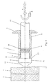
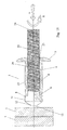
- FIG. 1 is a first embodiment of a blind rivet 3 according to the invention
- the one a set head 5 having blind rivet sleeve 4 and a coaxially guided in the bore 6 rivet mandrel 7, at the blind end 9 of the blind rivet 4 a mandrel head 8 with a cylindrical, to the longitudinal axis 10 of the mandrel 7 symmetrical portion 11 has, the Diameter larger than that of Blindniethülse 4 and is in a feed direction frustoconical portion 12 of the mandrel head 8 with the longitudinal axis 11 of the mandrel 7th perpendicular end face 13 passes.
- the blind end 9 of the blind rivet 4 is located with its annular end surface 14 at the end face 13 of the frustoconical Section 12 of the mandrel head 8 opposite end face 15 of the cylindrical portion 11 of the mandrel head 8 at.
- the rivet mandrel 7 is located at its in the blind rivet 4 Length section provided with a predetermined breaking point 16, preferably at the end of in Feed direction of the front third of his located in the blind rivet 4 length section.
- the entire blind rivet 3 is rotated with a rotational movement R and an axially directed feed force A against the mandrel head 8 facing first Part 1 pressure moderately led.
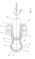
- This takes place in the processing area 17 of the first component. 1 by the axial force acting on the rotational movement R and in the feed direction Dornkopfes 8 caused friction and forming a heat input into the Component material, by which this is made flowable, as Fig. 2 illustrates.
- the rotating mandrel head 8 continues to form in this way continuously Components 1 and 2 passing through flow hole 18, the non-cutting of the blind rivet 3 continuously is penetrated until the setting head 5 of Blindniethggse 4 on the first component 1 for Plant comes.
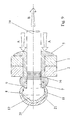
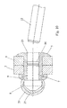
- Fig. 3 illustrates, with the surface of the mandrel head 8 and the Outer jacket 19 of Blindniethülse 4 at the blind end 9 by Reibungsversch conductedung cap-like manner, in such a way that according to the the components 1 and 2 successively in F diffuselochformen displaced superfluous Component materials form two overlapping caps 20 and 21, of which the outer Cap 20, the rear annular end face 15 of the mandrel head 8 against the end of the 9 Blind rivet sleeve 4 sealingly overlaps.
- FIGS. 6 to 10 shows a further procedure, which with the in connection With reference to FIGS. 1 to 5 described method for connecting components with one-sided Accessibility except for the difference that, as Fig. 6 shows that the mandrel head 8 of the rivet mandrel 7 of the blind rivet 3 facing first component 1 is provided with a pre-perforation 24 whose diameter is slightly larger than the diameter of the cylindrical Section 11 of the mandrel head 8 is.
- a pre-perforation 24 whose diameter is slightly larger than the diameter of the cylindrical Section 11 of the mandrel head 8 is.
- FIG. 6 and 7 shows the longitudinal axis 10 of the blind rivet 3 with respect to the center line 25 of the pre-perforation 24 of the first component 1 aligned in alignment and the mandrel head 8 of the rotated Blind rivet 3 then purposefully guided through the pre-perforation 24 of the first component 1 and through the axially directed feed force A against the component 1 facing surface 26 of the second Part 2 pressed.
- This is done in the processing area 27 of the second component 2 by the Friction and forming work, due to the rotational movement of the mandrel head 8 and the in Feed direction acting axial force of the mandrel head 8 is formed, a heat input in the second component 2, through which the component material is made flowable.
- the further process the sealingly firm connection of the two components 1 and 2 then corresponds to that in relation to Figs. 3 to 5 described procedure.
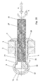
- FIGS. 11 to 15 another embodiment of the blind rivet 3 for connecting the Components 1 and 2 with one-sided accessibility according to the procedure of FIGS. 1 to 5, wherein the blind rivet 3 instead of the mandrel 7 according to FIGS. 1 to 10 a Blind rivet threaded bolt 28 which is guided in the Blindniethülse 4 and a mandrel head 8, which, as shown in the upper half of the sectional view of FIG. 11, identical as the mandrel head 8 of the mandrel 7 according to FIGS. 1 to 10 is formed.
- the blind rivet 4 and the blind rivet threaded bolt 28 are materially connected to the mandrel head 8, so that e.g. an absolute Tightness is possible.
- FIGS. 11 to 15 for connecting the two components 1 and 2 with one-sided accessibility corresponds to the principle of F thoroughlylochblindnietens of FIG. 1st to 5 with the difference that after sealingly firmly joining the two Components 1 and 2 through the Blindniet 3 of Blindnietgewindebolzen 28 continue from the open rear end 23 of Blindniethülse 4 extends and available for mounting purposes is.
- FIGS. 16 to 20 is a fourth embodiment of the method for connecting the both components 1 and 2 with one-sided accessibility, according to the procedure 6 to 10 to the effect that the blind rivet 3 facing component 1 with the corresponding Vorlochung 24 is provided and the rotated blind rivet 3 with the Mandrel 8 is guided purposefully through this Vorlochung 24.
- blind rivet 3 according to FIGS. 6 to 10 is shown in FIGS. 16 to 20 of the blind rivet 3 in accordance with FIG Embodiment according to FIGS. 11 to 15 provided with the Blindnietgewindebolzen 28.
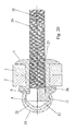
- Fig. 21 is a modified embodiment of the blind rivet 3 of FIG. 1 for connecting the two components 1 and 2 with one-sided accessibility, in which the jacket 30 of the frustoconical portion 12 of the mandrel head 8 with circumferential, the end face 13 of the Mandrel head 8 parallel grooves 31 is provided. Furthermore, the frusto-conical portion 12 of the mandrel head 8 at its transition to the cylindrical Section 11 of the mandrel head 8 be designed so that a relative to the cylindrical Section 12 radially projecting shoulder 32 is formed, as can be seen in Fig. 21. In the lower half of the sectional view of FIG. 21 is further shown that the blind rivet 4 and the rivet mandrel 7 in this embodiment of the blind rivet 3 materially together may be connected, e.g. absolute sealing is possible.
- FIG. 22 shows another embodiment of the blind rivet 3 in the blind rivet sleeve 4 guided Blindnietgewindebolzen 28 during compression of the blind end 9 of the Blind rivet 4 for riveting the two components 1 and 2, wherein according to FIG. 21 in Sheath 30 of the frustoconical portion 12 of the mandrel head 8 circumferential, the end face 13 of the mandrel head 8 parallel grooves 31 are provided and at the transition of the frustoconical D ornkopfab section 12 to the cylindrical mandrel head portion 11 a radial protruding paragraph 32 is formed.
- FIG. 22 shows another embodiment of the blind rivet 3 in the blind rivet sleeve 4 guided Blindnietgewindebolzen 28 during compression of the blind end 9 of the Blind rivet 4 for riveting the two components 1 and 2, wherein according to FIG. 21 in Sheath 30 of the frustoconical portion 12 of the mandrel head 8 circumferential, the end face 13 of the mandrel head 8 parallel groove
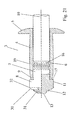
- Fig. 23 is another embodiment of the blind rivet 3 with setting head side of Blindniethülse 4 in one piece with this trained blind rivet nut 33 as a functional element.
- the rivet mandrel 7 guided in the blind rivet sleeve 4 is also provided with a rivet mandrel 7 in the latter lying predetermined breaking point 16 and the frusto-conical portion 12 of the Mandrel 8 of Nietdorns 7 formed with circumferential grooves 31, wherein at least one Edge of each groove 31 is parallel to the end face 13 of the mandrel head 8 and at the transition of the frustoconical mandrel head portion 12 to the cylindrical mandrel head portion 11 a radially paragraph 32 above.
- FIG. 23 In the lower half of the sectional view of FIG. 23 is also shown the alternative of the material connection of blind rivet 4 and rivet mandrel 7.
- the Blindniet 3 in the embodiment as blind rivet nut 35th According to Fig. 23 in the two components 1 and 2 sealingly interconnecting position shows, after compression of the blind-side end 9 of the blind rivet sleeve 4 up to the breakage of Rivet mandrel 7 at its lying in the blind rivet sleeve 16 breaking point 16 and after removal of Restnietdorns 22 from the blind rivet 4, the internal thread 34 of the setting head side Bore 35 of blind rivet nut 33 for mounting purposes e.g. by means of a not shown Threaded bolt available.
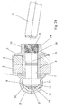
- blind rivet 3 shown in FIG. 25 which in particular has proven to be favorable in blind riveting of unilaterally accessible aluminum components, is on the end face 13 of the frustoconical mandrel head portion 12 coaxially in Feed direction extending frusto-conical centering element 36 with relatively provided small base diameter.
Landscapes
- Engineering & Computer Science (AREA)
- Mechanical Engineering (AREA)
- General Engineering & Computer Science (AREA)
- Insertion Pins And Rivets (AREA)
- Lining Or Joining Of Plastics Or The Like (AREA)
Priority Applications (3)
| Application Number | Priority Date | Filing Date | Title |
|---|---|---|---|
| DE50302005T DE50302005D1 (de) | 2003-07-26 | 2003-07-26 | Verfahren zum Verbinden von Bauteilen mit einseitiger Zugänglichkeit und Verbund von derartigen Bauteilen |
| EP03090235A EP1503089B1 (fr) | 2003-07-26 | 2003-07-26 | Méthode d'assemblage de pièces accessibles d'un seul côté et assemblage de telles pièces |
| AT03090235T ATE313719T1 (de) | 2003-07-26 | 2003-07-26 | Verfahren zum verbinden von bauteilen mit einseitiger zugänglichkeit und verbund von derartigen bauteilen |
Applications Claiming Priority (1)
| Application Number | Priority Date | Filing Date | Title |
|---|---|---|---|
| EP03090235A EP1503089B1 (fr) | 2003-07-26 | 2003-07-26 | Méthode d'assemblage de pièces accessibles d'un seul côté et assemblage de telles pièces |
Publications (2)
| Publication Number | Publication Date |
|---|---|
| EP1503089A1 true EP1503089A1 (fr) | 2005-02-02 |
| EP1503089B1 EP1503089B1 (fr) | 2005-12-21 |
Family
ID=33522362
Family Applications (1)
| Application Number | Title | Priority Date | Filing Date |
|---|---|---|---|
| EP03090235A Expired - Lifetime EP1503089B1 (fr) | 2003-07-26 | 2003-07-26 | Méthode d'assemblage de pièces accessibles d'un seul côté et assemblage de telles pièces |
Country Status (3)
| Country | Link |
|---|---|
| EP (1) | EP1503089B1 (fr) |
| AT (1) | ATE313719T1 (fr) |
| DE (1) | DE50302005D1 (fr) |
Cited By (18)
| Publication number | Priority date | Publication date | Assignee | Title |
|---|---|---|---|---|
| WO2008025327A3 (fr) * | 2006-08-26 | 2008-04-17 | Avdel Uk Ltd | Rivet aveugle autoperforant |
| DE102011001522A1 (de) * | 2011-03-24 | 2012-09-27 | Technische Universität Chemnitz | Verbindungselement, mit diesem hergestellte Verbindung zwischen wenigstens zwei sich überlappenden Bauteilen und Verfahren zur Herstellung dieser Verbindung |
| EP2286093A4 (fr) * | 2008-05-13 | 2015-04-08 | Co Operative Res Ct For Advanced Automotive Technology Ltd | Rivet aveugle et procédé d'assemblage associé |
| CN104863947A (zh) * | 2014-02-24 | 2015-08-26 | 格司帕空心铆钉技术有限责任公司 | 空心铆钉紧固件 |
| CN105257639A (zh) * | 2015-10-12 | 2016-01-20 | 贵州航天精工制造有限公司 | 一种锁紧销组件及其使用方法 |
| DE102015013233A1 (de) * | 2015-10-09 | 2017-04-13 | Audi Ag | Verfahren zur Herstellung eines Bauteilverbunds |
| EP2671654B1 (fr) * | 2012-06-05 | 2018-04-11 | Newfrey LLC | Rivet perforant, assemblage riveté et procédé de rivetage |
| CN108160898A (zh) * | 2016-12-07 | 2018-06-15 | 通用汽车环球科技运作有限责任公司 | 混合工件接合 |
| CN108421949A (zh) * | 2018-03-21 | 2018-08-21 | 李平 | 一种铝合金加工用铆钉自动安装装置 |
| CN109746377A (zh) * | 2019-01-15 | 2019-05-14 | 同济大学 | 热辅助热熔自攻单面铆接装置及方法 |
| CN111571143A (zh) * | 2020-05-26 | 2020-08-25 | 王丽 | 抽芯铆钉制作工艺 |
| EP3747568A1 (fr) * | 2019-06-03 | 2020-12-09 | GESIPA Blindniettechnik GmbH | Raccord de fixation de rivet aveugle, procédé de fabrication d'un raccord de fixation de rivet aveugle et fixation de rivet aveugle |
| CN113137419A (zh) * | 2021-04-21 | 2021-07-20 | 同济大学 | 一种抽芯铆钉、以及铆接方法 |
| GB2600415A (en) * | 2020-10-27 | 2022-05-04 | Airbus Operations Ltd | Blind fastener |
| CN117605746A (zh) * | 2023-12-14 | 2024-02-27 | 天津大学 | 一种用于热塑性复合材料与金属连接的热熔钻铆钉 |
| US12194603B2 (en) | 2018-09-05 | 2025-01-14 | Milwaukee Electric Tool Corporation | Blind rivet nut-setting tool |
| US12453999B2 (en) | 2021-07-28 | 2025-10-28 | Milwaukee Electric Tool Corporation | Blind rivet nut-setting tool |
| WO2025256601A1 (fr) * | 2024-06-12 | 2025-12-18 | 北京航为高科连接技术有限公司 | Rivet aveugle fileté sans fente et procédé de fabrication |
Families Citing this family (1)
| Publication number | Priority date | Publication date | Assignee | Title |
|---|---|---|---|---|
| US20060024145A1 (en) | 2004-07-29 | 2006-02-02 | Pei-Chung Wang | Friction stir rivet and method of joining therewith |
Citations (5)
| Publication number | Priority date | Publication date | Assignee | Title |
|---|---|---|---|---|
| DE4001723A1 (de) * | 1989-01-25 | 1990-07-26 | Shinjo Seisakusho Yk | Selbstbohrender blindniet und verfahren zur herstellung desselben |
| US4990042A (en) * | 1989-09-05 | 1991-02-05 | Szayer Geza J | Self-drilling blind setting rivet |
| DE19701252A1 (de) * | 1997-01-16 | 1998-07-23 | Hahn Ortwin | Verfahren und Verbindungsmittel zum Fügen von Blechen |
| DE19716431A1 (de) * | 1997-04-18 | 1998-10-22 | Franz Prof Dr Ing Tikal | Kombinationswerkzeug zum spanlosen Erzeugen eines Durchzuges mit einstellbarer zylindrischer Formlänge und variabler Durchzugseintrittsgeometrie |
| US20020125297A1 (en) * | 2000-12-20 | 2002-09-12 | Israel Stol | Friction plunge riveting |
-
2003
- 2003-07-26 EP EP03090235A patent/EP1503089B1/fr not_active Expired - Lifetime
- 2003-07-26 AT AT03090235T patent/ATE313719T1/de not_active IP Right Cessation
- 2003-07-26 DE DE50302005T patent/DE50302005D1/de not_active Expired - Lifetime
Patent Citations (5)
| Publication number | Priority date | Publication date | Assignee | Title |
|---|---|---|---|---|
| DE4001723A1 (de) * | 1989-01-25 | 1990-07-26 | Shinjo Seisakusho Yk | Selbstbohrender blindniet und verfahren zur herstellung desselben |
| US4990042A (en) * | 1989-09-05 | 1991-02-05 | Szayer Geza J | Self-drilling blind setting rivet |
| DE19701252A1 (de) * | 1997-01-16 | 1998-07-23 | Hahn Ortwin | Verfahren und Verbindungsmittel zum Fügen von Blechen |
| DE19716431A1 (de) * | 1997-04-18 | 1998-10-22 | Franz Prof Dr Ing Tikal | Kombinationswerkzeug zum spanlosen Erzeugen eines Durchzuges mit einstellbarer zylindrischer Formlänge und variabler Durchzugseintrittsgeometrie |
| US20020125297A1 (en) * | 2000-12-20 | 2002-09-12 | Israel Stol | Friction plunge riveting |
Cited By (26)
| Publication number | Priority date | Publication date | Assignee | Title |
|---|---|---|---|---|
| US8721241B2 (en) | 2006-08-26 | 2014-05-13 | Avdel Uk Limited | Self-tapping blind rivet |
| WO2008025327A3 (fr) * | 2006-08-26 | 2008-04-17 | Avdel Uk Ltd | Rivet aveugle autoperforant |
| EP2286093A4 (fr) * | 2008-05-13 | 2015-04-08 | Co Operative Res Ct For Advanced Automotive Technology Ltd | Rivet aveugle et procédé d'assemblage associé |
| DE102011001522A1 (de) * | 2011-03-24 | 2012-09-27 | Technische Universität Chemnitz | Verbindungselement, mit diesem hergestellte Verbindung zwischen wenigstens zwei sich überlappenden Bauteilen und Verfahren zur Herstellung dieser Verbindung |
| DE102011001522B4 (de) * | 2011-03-24 | 2015-03-19 | Technische Universität Chemnitz | Verbindungselement zur Herstellung einer Verbindung zwischen wenigstens zwei sich überlappenden Bauteilen und Verfahren zur Herstellung dieser Verbindung |
| EP2671654B1 (fr) * | 2012-06-05 | 2018-04-11 | Newfrey LLC | Rivet perforant, assemblage riveté et procédé de rivetage |
| CN104863947A (zh) * | 2014-02-24 | 2015-08-26 | 格司帕空心铆钉技术有限责任公司 | 空心铆钉紧固件 |
| DE102015013233B4 (de) * | 2015-10-09 | 2018-11-08 | Audi Ag | Verfahren zur Herstellung eines Bauteilverbunds |
| DE102015013233A1 (de) * | 2015-10-09 | 2017-04-13 | Audi Ag | Verfahren zur Herstellung eines Bauteilverbunds |
| CN105257639A (zh) * | 2015-10-12 | 2016-01-20 | 贵州航天精工制造有限公司 | 一种锁紧销组件及其使用方法 |
| CN105257639B (zh) * | 2015-10-12 | 2017-03-29 | 贵州航天精工制造有限公司 | 一种锁紧销组件及其使用方法 |
| US10682684B2 (en) | 2016-12-07 | 2020-06-16 | GM Global Technology Operations LLC | Hybrid workpiece joining |
| CN108160898A (zh) * | 2016-12-07 | 2018-06-15 | 通用汽车环球科技运作有限责任公司 | 混合工件接合 |
| CN108421949A (zh) * | 2018-03-21 | 2018-08-21 | 李平 | 一种铝合金加工用铆钉自动安装装置 |
| CN108421949B (zh) * | 2018-03-21 | 2019-10-25 | 季程康 | 一种铝合金加工用铆钉自动安装装置 |
| US12194603B2 (en) | 2018-09-05 | 2025-01-14 | Milwaukee Electric Tool Corporation | Blind rivet nut-setting tool |
| CN109746377A (zh) * | 2019-01-15 | 2019-05-14 | 同济大学 | 热辅助热熔自攻单面铆接装置及方法 |
| EP3747568A1 (fr) * | 2019-06-03 | 2020-12-09 | GESIPA Blindniettechnik GmbH | Raccord de fixation de rivet aveugle, procédé de fabrication d'un raccord de fixation de rivet aveugle et fixation de rivet aveugle |
| CN111571143A (zh) * | 2020-05-26 | 2020-08-25 | 王丽 | 抽芯铆钉制作工艺 |
| CN111571143B (zh) * | 2020-05-26 | 2022-03-04 | 王丽 | 抽芯铆钉制作工艺 |
| GB2600415A (en) * | 2020-10-27 | 2022-05-04 | Airbus Operations Ltd | Blind fastener |
| US12247605B2 (en) | 2020-10-27 | 2025-03-11 | Airbus Operations Limited | Blind fastener |
| CN113137419A (zh) * | 2021-04-21 | 2021-07-20 | 同济大学 | 一种抽芯铆钉、以及铆接方法 |
| US12453999B2 (en) | 2021-07-28 | 2025-10-28 | Milwaukee Electric Tool Corporation | Blind rivet nut-setting tool |
| CN117605746A (zh) * | 2023-12-14 | 2024-02-27 | 天津大学 | 一种用于热塑性复合材料与金属连接的热熔钻铆钉 |
| WO2025256601A1 (fr) * | 2024-06-12 | 2025-12-18 | 北京航为高科连接技术有限公司 | Rivet aveugle fileté sans fente et procédé de fabrication |
Also Published As
| Publication number | Publication date |
|---|---|
| DE50302005D1 (de) | 2006-01-26 |
| EP1503089B1 (fr) | 2005-12-21 |
| ATE313719T1 (de) | 2006-01-15 |
Similar Documents
| Publication | Publication Date | Title |
|---|---|---|
| EP1503089B1 (fr) | Méthode d'assemblage de pièces accessibles d'un seul côté et assemblage de telles pièces | |
| DE69420039T2 (de) | Selbstbohrender blindniet und verfahren zur herstellung einer druckdichten und nietartigen verbindung mittels eines solchen blindniets | |
| EP1926918B2 (fr) | Procede d'etablissement d'une liaison clouee et clou pour ce procede | |
| DE102007033126B4 (de) | Verfahren zum Herstellen einer Nagelverbindung sowie Nagel hierfür | |
| DE2606498C2 (de) | Befestigungsmittel | |
| EP1984635B1 (fr) | Rivet à frapper | |
| DE102011001522B4 (de) | Verbindungselement zur Herstellung einer Verbindung zwischen wenigstens zwei sich überlappenden Bauteilen und Verfahren zur Herstellung dieser Verbindung | |
| DE102004062391A1 (de) | Ein durch Nieten an ein Blechteil anbringbares Element sowie Zusammenbauteil und Verfahren zur Erzeugung des Zusammenbauteils | |
| WO1996019676A1 (fr) | Vis foreuse et taraudeuse et son procede de vissage | |
| WO1988005991A2 (fr) | Dispositif de fixation et son procede de fabrication | |
| DE69810502T2 (de) | Blindnieten | |
| DE10258238B4 (de) | Nagelschraube zur Herstellung einer Fügeverbindung, sowie ein Fügeverfahren unter Verwendung der Nagelschraube und eine Vorrichtung zur Durchführung des Fügeverfahrens | |
| DE4112591C1 (fr) | ||
| DE29509439U1 (de) | Stanzniet, insbesondere mit einem am Nietkopf angeformten Gewindebolzen | |
| DE102014104571A1 (de) | Selbststanzendes Funktionselement und ein Zusammenbauteil bestehend aus dem Funktionselement und einem Blechteil | |
| DE10325431A1 (de) | Verbindungsanordnung zweier Bauteile mit einem Blindniet und Verfahren zum Vernieten zweier Bauteile | |
| DE69608146T2 (de) | Verfahren zum Befestigen von Bauteilen und blinde Niete dafür | |
| DE102005054242B4 (de) | Verfahren zum Einbringen eines Fügehilfsteils mit einer gewindeähnlichen Struktur in zumindest zwei abschnittsweise übereinander angeordnete Fügeteile | |
| EP3936730B1 (fr) | Élément fonctionnel | |
| DE19531016C2 (de) | Verbindungselement, nach Art eines Niets | |
| DE102009035725A1 (de) | Selbstlochender Blindniet | |
| DE19701252A1 (de) | Verfahren und Verbindungsmittel zum Fügen von Blechen | |
| DE202006000666U1 (de) | Verbindungsanordnung zum Verbinden zweier Bauteile mittels eines Nagels | |
| EP4033113B1 (fr) | Élément fonctionnel d'auto-poinçonnage, pièce d'assemblage et procédé de fabrication d'une pièce d'assemblage | |
| EP4056863B1 (fr) | Élément fonctionnel |
Legal Events
| Date | Code | Title | Description |
|---|---|---|---|
| PUAI | Public reference made under article 153(3) epc to a published international application that has entered the european phase |
Free format text: ORIGINAL CODE: 0009012 |
|
| AK | Designated contracting states |
Kind code of ref document: A1 Designated state(s): AT BE BG CH CY CZ DE DK EE ES FI FR GB GR HU IE IT LI LU MC NL PT RO SE SI SK TR |
|
| AX | Request for extension of the european patent |
Extension state: AL LT LV MK |
|
| 17P | Request for examination filed |
Effective date: 20050212 |
|
| GRAP | Despatch of communication of intention to grant a patent |
Free format text: ORIGINAL CODE: EPIDOSNIGR1 |
|
| RTI1 | Title (correction) |
Free format text: METHOD FOR CONNECTING PIECES ACCESSIBLE ONLY FROM ONE SIDE AND ASSEMBLY OF SUCH PIECES |
|
| GRAS | Grant fee paid |
Free format text: ORIGINAL CODE: EPIDOSNIGR3 |
|
| GRAL | Information related to payment of fee for publishing/printing deleted |
Free format text: ORIGINAL CODE: EPIDOSDIGR3 |
|
| GRAS | Grant fee paid |
Free format text: ORIGINAL CODE: EPIDOSNIGR3 |
|
| AKX | Designation fees paid |
Designated state(s): AT BE BG CH CY CZ DE DK EE ES FI FR GB GR HU IE IT LI LU MC NL PT RO SE SI SK TR |
|
| GRAA | (expected) grant |
Free format text: ORIGINAL CODE: 0009210 |
|
| AK | Designated contracting states |
Kind code of ref document: B1 Designated state(s): AT BE BG CH CY CZ DE DK EE ES FI FR GB GR HU IE IT LI LU MC NL PT RO SE SI SK TR |
|
| PG25 | Lapsed in a contracting state [announced via postgrant information from national office to epo] |
Ref country code: IT Free format text: LAPSE BECAUSE OF FAILURE TO SUBMIT A TRANSLATION OF THE DESCRIPTION OR TO PAY THE FEE WITHIN THE PRESCRIBED TIME-LIMIT;WARNING: LAPSES OF ITALIAN PATENTS WITH EFFECTIVE DATE BEFORE 2007 MAY HAVE OCCURRED AT ANY TIME BEFORE 2007. THE CORRECT EFFECTIVE DATE MAY BE DIFFERENT FROM THE ONE RECORDED. Effective date: 20051221 Ref country code: IE Free format text: LAPSE BECAUSE OF FAILURE TO SUBMIT A TRANSLATION OF THE DESCRIPTION OR TO PAY THE FEE WITHIN THE PRESCRIBED TIME-LIMIT Effective date: 20051221 Ref country code: NL Free format text: LAPSE BECAUSE OF FAILURE TO SUBMIT A TRANSLATION OF THE DESCRIPTION OR TO PAY THE FEE WITHIN THE PRESCRIBED TIME-LIMIT Effective date: 20051221 Ref country code: SI Free format text: LAPSE BECAUSE OF FAILURE TO SUBMIT A TRANSLATION OF THE DESCRIPTION OR TO PAY THE FEE WITHIN THE PRESCRIBED TIME-LIMIT Effective date: 20051221 Ref country code: GB Free format text: LAPSE BECAUSE OF FAILURE TO SUBMIT A TRANSLATION OF THE DESCRIPTION OR TO PAY THE FEE WITHIN THE PRESCRIBED TIME-LIMIT Effective date: 20051221 Ref country code: CZ Free format text: LAPSE BECAUSE OF FAILURE TO SUBMIT A TRANSLATION OF THE DESCRIPTION OR TO PAY THE FEE WITHIN THE PRESCRIBED TIME-LIMIT Effective date: 20051221 Ref country code: FI Free format text: LAPSE BECAUSE OF FAILURE TO SUBMIT A TRANSLATION OF THE DESCRIPTION OR TO PAY THE FEE WITHIN THE PRESCRIBED TIME-LIMIT Effective date: 20051221 Ref country code: RO Free format text: LAPSE BECAUSE OF FAILURE TO SUBMIT A TRANSLATION OF THE DESCRIPTION OR TO PAY THE FEE WITHIN THE PRESCRIBED TIME-LIMIT Effective date: 20051221 Ref country code: SK Free format text: LAPSE BECAUSE OF FAILURE TO SUBMIT A TRANSLATION OF THE DESCRIPTION OR TO PAY THE FEE WITHIN THE PRESCRIBED TIME-LIMIT Effective date: 20051221 |
|
| REG | Reference to a national code |
Ref country code: GB Ref legal event code: FG4D Free format text: NOT ENGLISH |
|
| REG | Reference to a national code |
Ref country code: CH Ref legal event code: EP |
|
| REG | Reference to a national code |
Ref country code: IE Ref legal event code: FG4D Free format text: LANGUAGE OF EP DOCUMENT: GERMAN |
|
| REF | Corresponds to: |
Ref document number: 50302005 Country of ref document: DE Date of ref document: 20060126 Kind code of ref document: P |
|
| PG25 | Lapsed in a contracting state [announced via postgrant information from national office to epo] |
Ref country code: SE Free format text: LAPSE BECAUSE OF FAILURE TO SUBMIT A TRANSLATION OF THE DESCRIPTION OR TO PAY THE FEE WITHIN THE PRESCRIBED TIME-LIMIT Effective date: 20060321 Ref country code: DK Free format text: LAPSE BECAUSE OF FAILURE TO SUBMIT A TRANSLATION OF THE DESCRIPTION OR TO PAY THE FEE WITHIN THE PRESCRIBED TIME-LIMIT Effective date: 20060321 Ref country code: GR Free format text: LAPSE BECAUSE OF FAILURE TO SUBMIT A TRANSLATION OF THE DESCRIPTION OR TO PAY THE FEE WITHIN THE PRESCRIBED TIME-LIMIT Effective date: 20060321 Ref country code: BG Free format text: LAPSE BECAUSE OF FAILURE TO SUBMIT A TRANSLATION OF THE DESCRIPTION OR TO PAY THE FEE WITHIN THE PRESCRIBED TIME-LIMIT Effective date: 20060321 |
|
| PG25 | Lapsed in a contracting state [announced via postgrant information from national office to epo] |
Ref country code: ES Free format text: LAPSE BECAUSE OF FAILURE TO SUBMIT A TRANSLATION OF THE DESCRIPTION OR TO PAY THE FEE WITHIN THE PRESCRIBED TIME-LIMIT Effective date: 20060401 |
|
| PG25 | Lapsed in a contracting state [announced via postgrant information from national office to epo] |
Ref country code: PT Free format text: LAPSE BECAUSE OF FAILURE TO SUBMIT A TRANSLATION OF THE DESCRIPTION OR TO PAY THE FEE WITHIN THE PRESCRIBED TIME-LIMIT Effective date: 20060522 |
|
| NLV1 | Nl: lapsed or annulled due to failure to fulfill the requirements of art. 29p and 29m of the patents act | ||
| PG25 | Lapsed in a contracting state [announced via postgrant information from national office to epo] |
Ref country code: HU Free format text: LAPSE BECAUSE OF FAILURE TO SUBMIT A TRANSLATION OF THE DESCRIPTION OR TO PAY THE FEE WITHIN THE PRESCRIBED TIME-LIMIT Effective date: 20060622 |
|
| GBV | Gb: ep patent (uk) treated as always having been void in accordance with gb section 77(7)/1977 [no translation filed] |
Effective date: 20051221 |
|
| REG | Reference to a national code |
Ref country code: IE Ref legal event code: FD4D |
|
| PG25 | Lapsed in a contracting state [announced via postgrant information from national office to epo] |
Ref country code: BE Free format text: LAPSE BECAUSE OF NON-PAYMENT OF DUE FEES Effective date: 20060731 Ref country code: MC Free format text: LAPSE BECAUSE OF NON-PAYMENT OF DUE FEES Effective date: 20060731 |
|
| PLBE | No opposition filed within time limit |
Free format text: ORIGINAL CODE: 0009261 |
|
| STAA | Information on the status of an ep patent application or granted ep patent |
Free format text: STATUS: NO OPPOSITION FILED WITHIN TIME LIMIT |
|
| 26N | No opposition filed |
Effective date: 20060922 |
|
| EN | Fr: translation not filed | ||
| PG25 | Lapsed in a contracting state [announced via postgrant information from national office to epo] |
Ref country code: AT Free format text: LAPSE BECAUSE OF NON-PAYMENT OF DUE FEES Effective date: 20060726 |
|
| BERE | Be: lapsed |
Owner name: INPRO INNOVATIONSGESELLSCHAFT FUR FORTGESCHRITTENE Effective date: 20060731 |
|
| REG | Reference to a national code |
Ref country code: CH Ref legal event code: PL |
|
| PG25 | Lapsed in a contracting state [announced via postgrant information from national office to epo] |
Ref country code: LI Free format text: LAPSE BECAUSE OF NON-PAYMENT OF DUE FEES Effective date: 20070731 Ref country code: FR Free format text: LAPSE BECAUSE OF FAILURE TO SUBMIT A TRANSLATION OF THE DESCRIPTION OR TO PAY THE FEE WITHIN THE PRESCRIBED TIME-LIMIT Effective date: 20070209 Ref country code: CH Free format text: LAPSE BECAUSE OF NON-PAYMENT OF DUE FEES Effective date: 20070731 |
|
| PG25 | Lapsed in a contracting state [announced via postgrant information from national office to epo] |
Ref country code: EE Free format text: LAPSE BECAUSE OF FAILURE TO SUBMIT A TRANSLATION OF THE DESCRIPTION OR TO PAY THE FEE WITHIN THE PRESCRIBED TIME-LIMIT Effective date: 20051221 |
|
| PG25 | Lapsed in a contracting state [announced via postgrant information from national office to epo] |
Ref country code: LU Free format text: LAPSE BECAUSE OF NON-PAYMENT OF DUE FEES Effective date: 20060726 Ref country code: TR Free format text: LAPSE BECAUSE OF FAILURE TO SUBMIT A TRANSLATION OF THE DESCRIPTION OR TO PAY THE FEE WITHIN THE PRESCRIBED TIME-LIMIT Effective date: 20051221 |
|
| PG25 | Lapsed in a contracting state [announced via postgrant information from national office to epo] |
Ref country code: FR Free format text: LAPSE BECAUSE OF FAILURE TO SUBMIT A TRANSLATION OF THE DESCRIPTION OR TO PAY THE FEE WITHIN THE PRESCRIBED TIME-LIMIT Effective date: 20051221 Ref country code: CY Free format text: LAPSE BECAUSE OF FAILURE TO SUBMIT A TRANSLATION OF THE DESCRIPTION OR TO PAY THE FEE WITHIN THE PRESCRIBED TIME-LIMIT Effective date: 20051221 |
|
| PGFP | Annual fee paid to national office [announced via postgrant information from national office to epo] |
Ref country code: DE Payment date: 20160922 Year of fee payment: 14 |
|
| REG | Reference to a national code |
Ref country code: DE Ref legal event code: R119 Ref document number: 50302005 Country of ref document: DE |
|
| PG25 | Lapsed in a contracting state [announced via postgrant information from national office to epo] |
Ref country code: DE Free format text: LAPSE BECAUSE OF NON-PAYMENT OF DUE FEES Effective date: 20180201 |