EP4033113B1 - Élément fonctionnel d'auto-poinçonnage, pièce d'assemblage et procédé de fabrication d'une pièce d'assemblage - Google Patents
Élément fonctionnel d'auto-poinçonnage, pièce d'assemblage et procédé de fabrication d'une pièce d'assemblage Download PDFInfo
- Publication number
- EP4033113B1 EP4033113B1 EP21217677.0A EP21217677A EP4033113B1 EP 4033113 B1 EP4033113 B1 EP 4033113B1 EP 21217677 A EP21217677 A EP 21217677A EP 4033113 B1 EP4033113 B1 EP 4033113B1
- Authority
- EP
- European Patent Office
- Prior art keywords
- workpiece
- functional element
- punching
- self
- face
- Prior art date
- Legal status (The legal status is an assumption and is not a legal conclusion. Google has not performed a legal analysis and makes no representation as to the accuracy of the status listed.)
- Active
Links
Images


Classifications
-
- F—MECHANICAL ENGINEERING; LIGHTING; HEATING; WEAPONS; BLASTING
- F16—ENGINEERING ELEMENTS AND UNITS; GENERAL MEASURES FOR PRODUCING AND MAINTAINING EFFECTIVE FUNCTIONING OF MACHINES OR INSTALLATIONS; THERMAL INSULATION IN GENERAL
- F16B—DEVICES FOR FASTENING OR SECURING CONSTRUCTIONAL ELEMENTS OR MACHINE PARTS TOGETHER, e.g. NAILS, BOLTS, CIRCLIPS, CLAMPS, CLIPS OR WEDGES; JOINTS OR JOINTING
- F16B19/00—Bolts without screw-thread; Pins, including deformable elements; Rivets
- F16B19/04—Rivets; Spigots or the like fastened by riveting
- F16B19/08—Hollow rivets; Multi-part rivets
-
- F—MECHANICAL ENGINEERING; LIGHTING; HEATING; WEAPONS; BLASTING
- F16—ENGINEERING ELEMENTS AND UNITS; GENERAL MEASURES FOR PRODUCING AND MAINTAINING EFFECTIVE FUNCTIONING OF MACHINES OR INSTALLATIONS; THERMAL INSULATION IN GENERAL
- F16B—DEVICES FOR FASTENING OR SECURING CONSTRUCTIONAL ELEMENTS OR MACHINE PARTS TOGETHER, e.g. NAILS, BOLTS, CIRCLIPS, CLAMPS, CLIPS OR WEDGES; JOINTS OR JOINTING
- F16B37/00—Nuts or like thread-engaging members
- F16B37/04—Devices for fastening nuts to surfaces, e.g. sheets, plates
- F16B37/06—Devices for fastening nuts to surfaces, e.g. sheets, plates by means of welding or riveting
- F16B37/062—Devices for fastening nuts to surfaces, e.g. sheets, plates by means of welding or riveting by means of riveting
- F16B37/065—Devices for fastening nuts to surfaces, e.g. sheets, plates by means of welding or riveting by means of riveting by deforming the material of the nut
-
- F—MECHANICAL ENGINEERING; LIGHTING; HEATING; WEAPONS; BLASTING
- F16—ENGINEERING ELEMENTS AND UNITS; GENERAL MEASURES FOR PRODUCING AND MAINTAINING EFFECTIVE FUNCTIONING OF MACHINES OR INSTALLATIONS; THERMAL INSULATION IN GENERAL
- F16B—DEVICES FOR FASTENING OR SECURING CONSTRUCTIONAL ELEMENTS OR MACHINE PARTS TOGETHER, e.g. NAILS, BOLTS, CIRCLIPS, CLAMPS, CLIPS OR WEDGES; JOINTS OR JOINTING
- F16B35/00—Screw-bolts; Stay-bolts; Screw-threaded studs; Screws; Set screws
- F16B35/04—Screw-bolts; Stay-bolts; Screw-threaded studs; Screws; Set screws with specially-shaped head or shaft in order to fix the bolt on or in an object
- F16B35/06—Specially-shaped heads
-
- B—PERFORMING OPERATIONS; TRANSPORTING
- B21—MECHANICAL METAL-WORKING WITHOUT ESSENTIALLY REMOVING MATERIAL; PUNCHING METAL
- B21J—FORGING; HAMMERING; PRESSING METAL; RIVETING; FORGE FURNACES
- B21J15/00—Riveting
- B21J15/10—Riveting machines
-
- F—MECHANICAL ENGINEERING; LIGHTING; HEATING; WEAPONS; BLASTING
- F16—ENGINEERING ELEMENTS AND UNITS; GENERAL MEASURES FOR PRODUCING AND MAINTAINING EFFECTIVE FUNCTIONING OF MACHINES OR INSTALLATIONS; THERMAL INSULATION IN GENERAL
- F16B—DEVICES FOR FASTENING OR SECURING CONSTRUCTIONAL ELEMENTS OR MACHINE PARTS TOGETHER, e.g. NAILS, BOLTS, CIRCLIPS, CLAMPS, CLIPS OR WEDGES; JOINTS OR JOINTING
- F16B19/00—Bolts without screw-thread; Pins, including deformable elements; Rivets
- F16B19/04—Rivets; Spigots or the like fastened by riveting
-
- F—MECHANICAL ENGINEERING; LIGHTING; HEATING; WEAPONS; BLASTING
- F16—ENGINEERING ELEMENTS AND UNITS; GENERAL MEASURES FOR PRODUCING AND MAINTAINING EFFECTIVE FUNCTIONING OF MACHINES OR INSTALLATIONS; THERMAL INSULATION IN GENERAL
- F16B—DEVICES FOR FASTENING OR SECURING CONSTRUCTIONAL ELEMENTS OR MACHINE PARTS TOGETHER, e.g. NAILS, BOLTS, CIRCLIPS, CLAMPS, CLIPS OR WEDGES; JOINTS OR JOINTING
- F16B37/00—Nuts or like thread-engaging members
- F16B37/04—Devices for fastening nuts to surfaces, e.g. sheets, plates
- F16B37/06—Devices for fastening nuts to surfaces, e.g. sheets, plates by means of welding or riveting
- F16B37/062—Devices for fastening nuts to surfaces, e.g. sheets, plates by means of welding or riveting by means of riveting
- F16B37/068—Devices for fastening nuts to surfaces, e.g. sheets, plates by means of welding or riveting by means of riveting by deforming the material of the support, e.g. the sheet or plate
-
- F—MECHANICAL ENGINEERING; LIGHTING; HEATING; WEAPONS; BLASTING
- F16—ENGINEERING ELEMENTS AND UNITS; GENERAL MEASURES FOR PRODUCING AND MAINTAINING EFFECTIVE FUNCTIONING OF MACHINES OR INSTALLATIONS; THERMAL INSULATION IN GENERAL
- F16B—DEVICES FOR FASTENING OR SECURING CONSTRUCTIONAL ELEMENTS OR MACHINE PARTS TOGETHER, e.g. NAILS, BOLTS, CIRCLIPS, CLAMPS, CLIPS OR WEDGES; JOINTS OR JOINTING
- F16B39/00—Locking of screws, bolts or nuts
- F16B39/22—Locking of screws, bolts or nuts in which the locking takes place during screwing down or tightening
- F16B39/28—Locking of screws, bolts or nuts in which the locking takes place during screwing down or tightening by special members on, or shape of, the nut or bolt
- F16B39/282—Locking by means of special shape of work-engaging surfaces, e.g. notched or toothed nuts
-
- F—MECHANICAL ENGINEERING; LIGHTING; HEATING; WEAPONS; BLASTING
- F16—ENGINEERING ELEMENTS AND UNITS; GENERAL MEASURES FOR PRODUCING AND MAINTAINING EFFECTIVE FUNCTIONING OF MACHINES OR INSTALLATIONS; THERMAL INSULATION IN GENERAL
- F16B—DEVICES FOR FASTENING OR SECURING CONSTRUCTIONAL ELEMENTS OR MACHINE PARTS TOGETHER, e.g. NAILS, BOLTS, CIRCLIPS, CLAMPS, CLIPS OR WEDGES; JOINTS OR JOINTING
- F16B19/00—Bolts without screw-thread; Pins, including deformable elements; Rivets
- F16B19/04—Rivets; Spigots or the like fastened by riveting
- F16B19/08—Hollow rivets; Multi-part rivets
- F16B19/086—Self-piercing rivets
Definitions
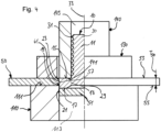
- the invention relates to a self-punching functional element for fastening to a workpiece, namely to a high-strength sheet metal part, an assembly part comprising a workpiece and a functional element, and a method for producing an assembly part.
- Such functional elements usually have a functional section, which in turn is used to attach other components. They are widely used in automotive engineering, among other areas.
- Functional elements can be bolt elements, the shaft of which can be provided with a thread, or nut elements, which have, for example, an internal thread.
- Functional elements are known in various designs. On the one hand, there are, for example, rivet elements that have a rivet section that is deformed when attached to a sheet metal part to form a rivet flange and, with the head part, to form an annular receptacle for the edge of a hole in the sheet metal part. With such rivet elements, the functional element is deformed when attached to the sheet metal part.
- Press-in elements are also known in which the element itself is not intentionally deformed when attached to a sheet metal part, but rather the sheet metal material itself is deformed in order to bring it into engagement with undercuts of the respective press-in element.
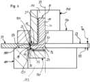
- a fastening element which is self-piercing and can also be attached to a regular sheet metal part as a rivet element.
- the fastening element has a punching and riveting section, at the free end of which a punching edge is provided radially on the inside.
- welded joints are often used, especially when the workpiece is a high-strength sheet metal part.
- Workpieces that have a strength of more than 1200 MPa, in particular around 1500 MPa to 1900 MPa, and are usually made of high-strength steel, are referred to as "high-strength”.
- high-strength steel is difficult to weld.
- the functional element which is usually made of steel, can be a bolt element or a nut element.
- a shaft of the press-in bolt preferably has an external thread and thus forms the functional section.
- the nut element on the other hand, preferably has an internal thread, which forms the functional section.
- other features can also be provided, which are suitable, for example, for fastening another component or for providing another functionality.
- the functional section can also be designed in sections or completely as a smooth pin or as a smooth hole.
- the fastening section is the section of the functional element with which the functional element is fastened to the workpiece.
- the two undercuts acting in the axial direction ensure a secure hold of the functional element in the sheet metal part, whereby pre-drilling of the
- the second undercut can only be formed after pressing in, in particular by means of a die punch, which means that a large range of possible workpiece thicknesses can be covered.
- the fastening section advantageously has an axial extension that is greater than the thickness of the workpiece.
- the die punch preferably has a forming surface which diverges from the end face in order to force material of the fastening section radially outward and thus form the second undercut.
- it is designed in such a way that it simultaneously fixes the workpiece 50 and the element 10 in the axial direction.
Landscapes
- Engineering & Computer Science (AREA)
- General Engineering & Computer Science (AREA)
- Mechanical Engineering (AREA)
- Connection Of Plates (AREA)
- Transition And Organic Metals Composition Catalysts For Addition Polymerization (AREA)
- Reinforced Plastic Materials (AREA)
- Laminated Bodies (AREA)
Claims (16)
- Elément fonctionnel auto-poinçonneur (10) destiné à être fixé à une pièce à oeuvrer (50), à savoir à une pièce de tôle à haute résistance, comprenantune portion fonctionnelle (11) etune portion de fixation (13), présentantune surface de pression (15) pour l'engagement d'un dispositif de pose (140),une surface frontale (17) réalisée en forme annulaire, détournée de la surface de pression (15), etune surface périphérique extérieure (19) reliant la surface de pression (15) et la surface frontale (17),au moins une saillie (23) étant prévue sur la surface périphérique extérieure (19) au voisinage de la surface de pression (15), saillie qui s'élève de la surface périphérique extérieure (19) dans la direction radiale,caractérisé en ce quela surface frontale (17) est délimitée radialement à l'extérieur par une arête de poinçonnage (21) destinée à découper une pastille (51) dans la pièce à oeuvrer (50),en ce que la saillie (23) s'étend plus loin vers l'extérieur dans la direction radiale que l'arête de poinçonnage (21), eten ce que la largeur de l'anneau de surface frontale est supérieure à 70 % de l'extension axiale de la portion de fixation (13) ou de l'extension axiale de la surface périphérique extérieure (19).
- Elément fonctionnel auto-poinçonneur (10) selon la revendication 1,
caractérisé en ce que
la saillie (23) est de forme conique et/ou, vue par rapport à un axe longitudinal (33) de l'élément fonctionnel (10), présente un tracé au moins localement incurvé et/ou oblique. - Elément fonctionnel auto-poinçonneur (10) selon la revendication 1 ou 2, caractérisé en ce que
une extension radiale maximale de la saillie (23) est disposée au voisinage ou de façon adjacente à une transition (25) vers la surface de pression (15). - Elément fonctionnel auto-poinçonneur (10) selon l'une des revendications 1 à 3,
caractérisé en ce que
la saillie (23) présente une extension axiale qui correspond à environ 30 % à 60 %, en particulier à environ 35 % à 45 %, d'une extension axiale de la portion de fixation (13). - Elément fonctionnel auto-poinçonneur (10) selon l'une des revendications 1 à 4,
caractérisé parau moins une caractéristique anti-rotation (27) formée sur la surface périphérique extérieure (19), qui est de préférence réalisée sous la forme d'une nervure s'élevant de la surface périphérique extérieure (19) et s'étendant dans la direction axiale,en particulier, une extension radiale de la caractéristique anti-rotation (27) correspond sensiblement à une extension radiale maximale de la saillie (23). - Elément fonctionnel auto-poinçonneur (10) selon l'une des revendications 1 à 5,
caractérisé en ce quela surface de pression (15) est réalisée en forme annulaire, et/ouen ce que la surface frontale (17) présente un renfoncement (29) disposé en particulier au centre. - Elément fonctionnel auto-poinçonneur (10) selon l'une des revendications 1 à 6,
caractérisé en ce que
la largeur de l'anneau de surface frontale est supérieure à 80 % ou supérieure à 90 % de l'extension axiale de la portion de fixation (13) ou de l'extension axiale de la surface périphérique extérieure (19). - Elément fonctionnel auto-poinçonneur (10) selon l'une des revendications 1 à 7,
caractérisé en ce que
la saillie (23) est continue dans la direction périphérique, et/ou en ce qu'il est prévu au moins deux saillies (23) disposées séparément l'une de l'autre dans la direction périphérique. - Elément fonctionnel auto-poinçonneur (10) selon l'une des revendications 1 à 8,
caractérisé en ce quela portion fonctionnelle (11) est pourvue d'un pas de vis (31) ou d'un moyen d'enclenchement, et/ouen ce que l'élément fonctionnel (10) est un élément formant boulon ou un élément formant écrou. - Pièce d'assemblage (100) comprenant une pièce à oeuvrer (50), en particulier une pièce en tôle à haute résistance, ayant une première surface (53), une deuxième surface (55) opposée à la première surface (53), et un trou de poinçonnage (57) qui forme une surface périphérique intérieure (59), dans laquelle un élément fonctionnel auto-poinçonneur (10) selon l'une des revendications 1 à 9 est enfoncé dans le trou de poinçonnage (57) en découpant une pastille de poinçonnage (51), de sorte que la surface périphérique extérieure (19) de l'élément fonctionnel (10) vient en contact avec la surface périphérique intérieure (59) du trou de poinçonnage (57) et que la saillie (23) s'engage dans la première surface (53) de la pièce à oeuvrer (50) ou coopère avec celle-ci, de manière à fournir une première contre-dépouille (61) agissant dans la direction axiale, le matériau déplacé de la portion de fixation (13) formant une deuxième contre-dépouille (63) entourant la pièce à oeuvrer (50) sur la deuxième surface (55), afin de fixer l'élément fonctionnel (10) à la pièce à oeuvrer (50).
- Pièce d'assemblage (100) selon la revendication 10,
caractérisée en ce que
la surface de pression (15) est alignée approximativement à fleur avec la première surface (53). - Pièce d'assemblage (100) selon la revendication 10 ou 11,
caractérisée en ce que
la portion de fixation (13) présente, sur la surface frontale (17), une dépression (35) à partir de laquelle la deuxième contre-dépouille (63) s'étend vers l'extérieur dans la direction radiale. - Pièce d'assemblage (100) selon l'une des revendications 10 à 12,
caractérisée en ce que
la portion de fixation (13) présente une extension axiale supérieure à l'épaisseur (T50) de la pièce à oeuvrer (50). - Procédé de fabrication d'une pièce d'assemblage (100) selon l'une des revendications 10 à 13, comprenant les étapes consistant à :- fournir un élément fonctionnel auto-poinçonneur (10) selon l'une au moins des revendications 1 à 9,- fournir une pièce à oeuvrer (50), en particulier une pièce de tôle à haute résistance, qui n'est pas pré-perforée au moins dans une zone prévue pour la fixation de l'élément fonctionnel (10),- presser la surface frontale (17) de l'élément fonctionnel (10) contre la pièce à oeuvrer (50), de sorte qu'une pastille de poinçonnage (51) est découpée de la pièce à oeuvrer (50) par l'arête de poinçonnage (21) en formant un trou de poinçonnage (57), l'élément fonctionnel (10) étant enfoncé dans la pièce à oeuvrer (50) au moins jusqu'à ce que la saillie (23) vienne en engagement avec la première surface (53) de la pièce à oeuvrer (50) et/ou avec la surface périphérique intérieure (59) du trou de poinçonnage (57) pour former la première contre-dépouille (61),- déformer la portion de fixation (13) au moins dans une zone voisine de l'arête de poinçonnage (21) pour former la deuxième contre-dépouille (63), en particulier, il est prévu un poinçon de matrice (120) qui est pressé contre la surface frontale (17) de la portion de fixation (13) pour déformer la portion de fixation (13).
- Procédé selon la revendication 14,
caractérisé en ce quel'élément fonctionnel (10) est pressé contre la pièce à oeuvrer (50) par un dispositif de pose (140) qui agit sur la surface de pression (15) de l'élément fonctionnel (10), et/ouen ce qu'il est prévu un serre-flan (130) par lequel la deuxième surface (55) de la pièce à oeuvrer (50) est pressée contre une surface d'appui (111) d'une matrice (110). - Procédé selon l'une des revendications 14 à 15,
caractérisé en ce que
le poinçon de matrice (120) présente une surface de déformation (121) qui diverge par rapport à la surface frontale (17) afin de pousser le matériau de la portion de fixation (13) radialement vers l'extérieur et de former ainsi la deuxième contre-dépouille (63).
Applications Claiming Priority (1)
| Application Number | Priority Date | Filing Date | Title |
|---|---|---|---|
| DE102021101366.6A DE102021101366A1 (de) | 2021-01-22 | 2021-01-22 | Selbststanzendes Funktionselement, Zusammenbauteil und Verfahren zur Herstellung eines Zusammenbauteils |
Publications (2)
| Publication Number | Publication Date |
|---|---|
| EP4033113A1 EP4033113A1 (fr) | 2022-07-27 |
| EP4033113B1 true EP4033113B1 (fr) | 2024-07-03 |
Family
ID=79164420
Family Applications (1)
| Application Number | Title | Priority Date | Filing Date |
|---|---|---|---|
| EP21217677.0A Active EP4033113B1 (fr) | 2021-01-22 | 2021-12-24 | Élément fonctionnel d'auto-poinçonnage, pièce d'assemblage et procédé de fabrication d'une pièce d'assemblage |
Country Status (6)
| Country | Link |
|---|---|
| US (1) | US12078199B2 (fr) |
| EP (1) | EP4033113B1 (fr) |
| CN (1) | CN114810772B (fr) |
| DE (1) | DE102021101366A1 (fr) |
| ES (1) | ES2986980T3 (fr) |
| PL (1) | PL4033113T3 (fr) |
Family Cites Families (16)
| Publication number | Priority date | Publication date | Assignee | Title |
|---|---|---|---|---|
| NL283819A (fr) * | 1958-06-24 | |||
| US4555838A (en) | 1983-03-28 | 1985-12-03 | Multifastener Corp. | Method of installing self-attaching fasteners |
| DE10015239A1 (de) * | 2000-03-27 | 2001-10-04 | Profil Verbindungstechnik Gmbh | Funktionselementanordnung, Funktionselement, Hilfsfügeteil, Zusammenbauteil und Verfahren zur Herstellung eines Zusammenbauteils |
| DE10243759B4 (de) * | 2002-09-20 | 2011-08-11 | PROFIL Verbindungstechnik GmbH & Co. KG, 61381 | Verfahren zur Erzeugung einer elektrisch leitenden Verbindung zwischen einer elektrischen Anschlusseinrichtung wie ein Kabelschuh und einem Blechteil, Befestigungselement und Zusammenbauteil |
| US7425111B2 (en) * | 2002-10-16 | 2008-09-16 | Whitesell International Corporation | Torque resistant fastening element |
| US7179034B2 (en) * | 2002-10-16 | 2007-02-20 | Whitesell International Corporation | Torque resistant fastening element |
| US20050025605A1 (en) * | 2003-07-30 | 2005-02-03 | Vrana John J. | Locator stud and method of assembly |
| DE102008052383A1 (de) * | 2008-10-20 | 2010-04-22 | Profil Verbindungstechnik Gmbh & Co. Kg | Zusammenbauteil bestehend aus einem Befestigungselement und einem Blechteil sowie ein Verfahren zur Herstellung eines solchen Zusammenbauteils |
| DE102009037427A1 (de) * | 2009-08-13 | 2011-02-17 | Profil Verbindungstechnik Gmbh & Co. Kg | Funktionselement, Verfahren zum Einbringen des Funktionselementes in ein Blechteil sowie Zusammenbauteil |
| DE102009042336A1 (de) | 2009-09-21 | 2011-03-24 | Profil Verbindungstechnik Gmbh & Co. Kg | Selbststanzendes hohles Einpresselement, Zusammenbauteil bestehend aus einem Einpresselement und einem Blechteil sowie ein Verfahren zur Herstellung einer selbststanzenden Einpressmutter sowie zur Anbringung einer selbststanzenden Einpressmutter |
| DE102010032866A1 (de) | 2010-07-30 | 2012-02-02 | Profil Verbindungstechnik Gmbh & Co. Kg | Selbststanzendes Mutterelement und Zusammenbauteil bestehend aus dem Mutterelement und einem Blechteil |
| DE102015101950A1 (de) * | 2015-02-11 | 2016-08-11 | Newfrey Llc | Stanzniet und Verfahren zum Herstellen einer Stanznietverbindung |
| EP3319785B1 (fr) * | 2015-07-09 | 2021-09-29 | WoodWelding AG | Liaison d'objets ensemble |
| DE102016119479A1 (de) | 2016-10-12 | 2018-04-12 | Profil Verbindungstechnik Gmbh & Co. Kg | Funktionselement zur fluiddichten Anbringung an ein Blechteil, Zusammenbauteil und Verfahren |
| DE102018117131A1 (de) * | 2018-07-16 | 2020-01-16 | Profil Verbindungstechnik Gmbh & Co. Kg | Selbststanzendes Element und Zusammenbauteil bestehend aus dem Element und einem Blechteil |
| DE102019117086A1 (de) * | 2019-06-25 | 2020-12-31 | Profil Verbindungstechnik Gmbh & Co. Kg | Befestigungseinheit |
-
2021
- 2021-01-22 DE DE102021101366.6A patent/DE102021101366A1/de active Pending
- 2021-12-24 ES ES21217677T patent/ES2986980T3/es active Active
- 2021-12-24 EP EP21217677.0A patent/EP4033113B1/fr active Active
- 2021-12-24 PL PL21217677.0T patent/PL4033113T3/pl unknown
-
2022
- 2022-01-20 CN CN202210063069.3A patent/CN114810772B/zh active Active
- 2022-01-21 US US17/580,925 patent/US12078199B2/en active Active
Also Published As
| Publication number | Publication date |
|---|---|
| US12078199B2 (en) | 2024-09-03 |
| ES2986980T3 (es) | 2024-11-13 |
| DE102021101366A1 (de) | 2022-07-28 |
| US20220235811A1 (en) | 2022-07-28 |
| PL4033113T3 (pl) | 2024-11-12 |
| EP4033113A1 (fr) | 2022-07-27 |
| CN114810772A (zh) | 2022-07-29 |
| CN114810772B (zh) | 2024-04-09 |
Similar Documents
| Publication | Publication Date | Title |
|---|---|---|
| EP2549128B1 (fr) | Elément fonctionnel avec propriétés de sécurisation contre la torsion et composant composé d'un élément fonctionnel et d'une partie en tôle | |
| EP2486288B1 (fr) | Liaison entre deux éléments en plastique renforcé et son procédé de fabrication | |
| EP2177776B1 (fr) | Assemblage comprenant un élément de fixation et un élément en tôle et procédé de fabrication d'un tel élément d'ensemble | |
| EP1674741B1 (fr) | Elément à montage par rivetage dans une pièce en tôle, procédé de montage et ensemble ainsi formé | |
| EP2412991B1 (fr) | Elément d'écrou auto-perforant et composant constitué de l'élément d'écrou et d'un élément de tôle | |
| EP2980426B1 (fr) | Composant d'assemblage comprenant un element a sertir et une partie de tole | |
| EP1918596B1 (fr) | Rivet aveugle et son utilisation | |
| DE102011001522B4 (de) | Verbindungselement zur Herstellung einer Verbindung zwischen wenigstens zwei sich überlappenden Bauteilen und Verfahren zur Herstellung dieser Verbindung | |
| WO2017157959A1 (fr) | Elément d'insertion à force autoperforant, assemblage par insertion à force et procédé pour réaliser un tel assemblage par insertion à force | |
| WO2009121670A1 (fr) | Rivet plein destiné à assembler des pièces composites | |
| DE102016204619A1 (de) | Einpressverbindung zwischen einem hochfesten Bauteil und einem Einpresselement, Verfahren zur Ausbildung einer solchen Einpressverbindung sowie Einpresselement für eine solche Einpressverbindung | |
| EP3366384B1 (fr) | Methode de fabrication d'un rivet aveugle, rivet aveugle et assemblage de fixation | |
| DE102018117131A1 (de) | Selbststanzendes Element und Zusammenbauteil bestehend aus dem Element und einem Blechteil | |
| EP0759510A1 (fr) | Corps creux, matrice pour le corps creux, méthode pour la fixation d'un corps creux sur un élément en forme plate et ensemble de montage | |
| DE102006021843A1 (de) | Abstandsniet, Nietverbindung und Verfahren zu ihrer Herstellung | |
| DE102010008554A1 (de) | Nietelement, insbesondere zum Hydrostanznieten, und damit durchgeführtes Fügeverfahren sowie unter Verwendung des Nietelements hergestellte Gegenstände | |
| DE102014104571A1 (de) | Selbststanzendes Funktionselement und ein Zusammenbauteil bestehend aus dem Funktionselement und einem Blechteil | |
| EP3936730B1 (fr) | Élément fonctionnel | |
| EP4033113B1 (fr) | Élément fonctionnel d'auto-poinçonnage, pièce d'assemblage et procédé de fabrication d'une pièce d'assemblage | |
| WO2002083357A1 (fr) | Procede pour monter un element fonctionnel sur un composant et outil utilise a cet effet | |
| EP4083451B1 (fr) | Élément fonctionnel auto-poinçonnant, composant d'assemblage et procédé de fabrication d'un composant d'assemblage | |
| DE19531016C2 (de) | Verbindungselement, nach Art eines Niets | |
| EP3877105B1 (fr) | Unité de fixation | |
| DE102020118262A1 (de) | Funktionselement | |
| EP3974660A1 (fr) | Élément de fixation auto-poinçonnant |
Legal Events
| Date | Code | Title | Description |
|---|---|---|---|
| PUAI | Public reference made under article 153(3) epc to a published international application that has entered the european phase |
Free format text: ORIGINAL CODE: 0009012 |
|
| STAA | Information on the status of an ep patent application or granted ep patent |
Free format text: STATUS: THE APPLICATION HAS BEEN PUBLISHED |
|
| AK | Designated contracting states |
Kind code of ref document: A1 Designated state(s): AL AT BE BG CH CY CZ DE DK EE ES FI FR GB GR HR HU IE IS IT LI LT LU LV MC MK MT NL NO PL PT RO RS SE SI SK SM TR |
|
| STAA | Information on the status of an ep patent application or granted ep patent |
Free format text: STATUS: REQUEST FOR EXAMINATION WAS MADE |
|
| 17P | Request for examination filed |
Effective date: 20221228 |
|
| RBV | Designated contracting states (corrected) |
Designated state(s): AL AT BE BG CH CY CZ DE DK EE ES FI FR GB GR HR HU IE IS IT LI LT LU LV MC MK MT NL NO PL PT RO RS SE SI SK SM TR |
|
| GRAP | Despatch of communication of intention to grant a patent |
Free format text: ORIGINAL CODE: EPIDOSNIGR1 |
|
| STAA | Information on the status of an ep patent application or granted ep patent |
Free format text: STATUS: GRANT OF PATENT IS INTENDED |
|
| RIC1 | Information provided on ipc code assigned before grant |
Ipc: F16B 19/08 20060101ALN20240315BHEP Ipc: F16B 37/06 20060101AFI20240315BHEP |
|
| INTG | Intention to grant announced |
Effective date: 20240412 |
|
| GRAS | Grant fee paid |
Free format text: ORIGINAL CODE: EPIDOSNIGR3 |
|
| GRAA | (expected) grant |
Free format text: ORIGINAL CODE: 0009210 |
|
| STAA | Information on the status of an ep patent application or granted ep patent |
Free format text: STATUS: THE PATENT HAS BEEN GRANTED |
|
| AK | Designated contracting states |
Kind code of ref document: B1 Designated state(s): AL AT BE BG CH CY CZ DE DK EE ES FI FR GB GR HR HU IE IS IT LI LT LU LV MC MK MT NL NO PL PT RO RS SE SI SK SM TR |
|
| REG | Reference to a national code |
Ref country code: CH Ref legal event code: EP |
|
| REG | Reference to a national code |
Ref country code: DE Ref legal event code: R096 Ref document number: 502021004212 Country of ref document: DE |
|
| REG | Reference to a national code |
Ref country code: LT Ref legal event code: MG9D |
|
| REG | Reference to a national code |
Ref country code: NL Ref legal event code: MP Effective date: 20240703 |
|
| REG | Reference to a national code |
Ref country code: ES Ref legal event code: FG2A Ref document number: 2986980 Country of ref document: ES Kind code of ref document: T3 Effective date: 20241113 |
|
| PG25 | Lapsed in a contracting state [announced via postgrant information from national office to epo] |
Ref country code: PT Free format text: LAPSE BECAUSE OF FAILURE TO SUBMIT A TRANSLATION OF THE DESCRIPTION OR TO PAY THE FEE WITHIN THE PRESCRIBED TIME-LIMIT Effective date: 20241104 |
|
| PG25 | Lapsed in a contracting state [announced via postgrant information from national office to epo] |
Ref country code: NL Free format text: LAPSE BECAUSE OF FAILURE TO SUBMIT A TRANSLATION OF THE DESCRIPTION OR TO PAY THE FEE WITHIN THE PRESCRIBED TIME-LIMIT Effective date: 20240703 |
|
| PG25 | Lapsed in a contracting state [announced via postgrant information from national office to epo] |
Ref country code: PT Free format text: LAPSE BECAUSE OF FAILURE TO SUBMIT A TRANSLATION OF THE DESCRIPTION OR TO PAY THE FEE WITHIN THE PRESCRIBED TIME-LIMIT Effective date: 20241104 Ref country code: NL Free format text: LAPSE BECAUSE OF FAILURE TO SUBMIT A TRANSLATION OF THE DESCRIPTION OR TO PAY THE FEE WITHIN THE PRESCRIBED TIME-LIMIT Effective date: 20240703 |
|
| PG25 | Lapsed in a contracting state [announced via postgrant information from national office to epo] |
Ref country code: NO Free format text: LAPSE BECAUSE OF FAILURE TO SUBMIT A TRANSLATION OF THE DESCRIPTION OR TO PAY THE FEE WITHIN THE PRESCRIBED TIME-LIMIT Effective date: 20241003 |
|
| PG25 | Lapsed in a contracting state [announced via postgrant information from national office to epo] |
Ref country code: GR Free format text: LAPSE BECAUSE OF FAILURE TO SUBMIT A TRANSLATION OF THE DESCRIPTION OR TO PAY THE FEE WITHIN THE PRESCRIBED TIME-LIMIT Effective date: 20241004 Ref country code: FI Free format text: LAPSE BECAUSE OF FAILURE TO SUBMIT A TRANSLATION OF THE DESCRIPTION OR TO PAY THE FEE WITHIN THE PRESCRIBED TIME-LIMIT Effective date: 20240703 |
|
| PG25 | Lapsed in a contracting state [announced via postgrant information from national office to epo] |
Ref country code: BG Free format text: LAPSE BECAUSE OF FAILURE TO SUBMIT A TRANSLATION OF THE DESCRIPTION OR TO PAY THE FEE WITHIN THE PRESCRIBED TIME-LIMIT Effective date: 20240703 |
|
| PG25 | Lapsed in a contracting state [announced via postgrant information from national office to epo] |
Ref country code: LV Free format text: LAPSE BECAUSE OF FAILURE TO SUBMIT A TRANSLATION OF THE DESCRIPTION OR TO PAY THE FEE WITHIN THE PRESCRIBED TIME-LIMIT Effective date: 20240703 |
|
| PG25 | Lapsed in a contracting state [announced via postgrant information from national office to epo] |
Ref country code: IS Free format text: LAPSE BECAUSE OF FAILURE TO SUBMIT A TRANSLATION OF THE DESCRIPTION OR TO PAY THE FEE WITHIN THE PRESCRIBED TIME-LIMIT Effective date: 20241103 |
|
| PG25 | Lapsed in a contracting state [announced via postgrant information from national office to epo] |
Ref country code: HR Free format text: LAPSE BECAUSE OF FAILURE TO SUBMIT A TRANSLATION OF THE DESCRIPTION OR TO PAY THE FEE WITHIN THE PRESCRIBED TIME-LIMIT Effective date: 20240703 |
|
| PG25 | Lapsed in a contracting state [announced via postgrant information from national office to epo] |
Ref country code: RS Free format text: LAPSE BECAUSE OF FAILURE TO SUBMIT A TRANSLATION OF THE DESCRIPTION OR TO PAY THE FEE WITHIN THE PRESCRIBED TIME-LIMIT Effective date: 20241003 |
|
| PG25 | Lapsed in a contracting state [announced via postgrant information from national office to epo] |
Ref country code: RS Free format text: LAPSE BECAUSE OF FAILURE TO SUBMIT A TRANSLATION OF THE DESCRIPTION OR TO PAY THE FEE WITHIN THE PRESCRIBED TIME-LIMIT Effective date: 20241003 Ref country code: NO Free format text: LAPSE BECAUSE OF FAILURE TO SUBMIT A TRANSLATION OF THE DESCRIPTION OR TO PAY THE FEE WITHIN THE PRESCRIBED TIME-LIMIT Effective date: 20241003 Ref country code: LV Free format text: LAPSE BECAUSE OF FAILURE TO SUBMIT A TRANSLATION OF THE DESCRIPTION OR TO PAY THE FEE WITHIN THE PRESCRIBED TIME-LIMIT Effective date: 20240703 Ref country code: IS Free format text: LAPSE BECAUSE OF FAILURE TO SUBMIT A TRANSLATION OF THE DESCRIPTION OR TO PAY THE FEE WITHIN THE PRESCRIBED TIME-LIMIT Effective date: 20241103 Ref country code: HR Free format text: LAPSE BECAUSE OF FAILURE TO SUBMIT A TRANSLATION OF THE DESCRIPTION OR TO PAY THE FEE WITHIN THE PRESCRIBED TIME-LIMIT Effective date: 20240703 Ref country code: GR Free format text: LAPSE BECAUSE OF FAILURE TO SUBMIT A TRANSLATION OF THE DESCRIPTION OR TO PAY THE FEE WITHIN THE PRESCRIBED TIME-LIMIT Effective date: 20241004 Ref country code: FI Free format text: LAPSE BECAUSE OF FAILURE TO SUBMIT A TRANSLATION OF THE DESCRIPTION OR TO PAY THE FEE WITHIN THE PRESCRIBED TIME-LIMIT Effective date: 20240703 Ref country code: BG Free format text: LAPSE BECAUSE OF FAILURE TO SUBMIT A TRANSLATION OF THE DESCRIPTION OR TO PAY THE FEE WITHIN THE PRESCRIBED TIME-LIMIT Effective date: 20240703 |
|
| REG | Reference to a national code |
Ref country code: DE Ref legal event code: R097 Ref document number: 502021004212 Country of ref document: DE |
|
| PG25 | Lapsed in a contracting state [announced via postgrant information from national office to epo] |
Ref country code: DK Free format text: LAPSE BECAUSE OF FAILURE TO SUBMIT A TRANSLATION OF THE DESCRIPTION OR TO PAY THE FEE WITHIN THE PRESCRIBED TIME-LIMIT Effective date: 20240703 Ref country code: RO Free format text: LAPSE BECAUSE OF FAILURE TO SUBMIT A TRANSLATION OF THE DESCRIPTION OR TO PAY THE FEE WITHIN THE PRESCRIBED TIME-LIMIT Effective date: 20240703 Ref country code: SM Free format text: LAPSE BECAUSE OF FAILURE TO SUBMIT A TRANSLATION OF THE DESCRIPTION OR TO PAY THE FEE WITHIN THE PRESCRIBED TIME-LIMIT Effective date: 20240703 |
|
| PG25 | Lapsed in a contracting state [announced via postgrant information from national office to epo] |
Ref country code: EE Free format text: LAPSE BECAUSE OF FAILURE TO SUBMIT A TRANSLATION OF THE DESCRIPTION OR TO PAY THE FEE WITHIN THE PRESCRIBED TIME-LIMIT Effective date: 20240703 |
|
| PG25 | Lapsed in a contracting state [announced via postgrant information from national office to epo] |
Ref country code: SK Free format text: LAPSE BECAUSE OF FAILURE TO SUBMIT A TRANSLATION OF THE DESCRIPTION OR TO PAY THE FEE WITHIN THE PRESCRIBED TIME-LIMIT Effective date: 20240703 |
|
| PLBE | No opposition filed within time limit |
Free format text: ORIGINAL CODE: 0009261 |
|
| STAA | Information on the status of an ep patent application or granted ep patent |
Free format text: STATUS: NO OPPOSITION FILED WITHIN TIME LIMIT |
|
| 26N | No opposition filed |
Effective date: 20250404 |
|
| PG25 | Lapsed in a contracting state [announced via postgrant information from national office to epo] |
Ref country code: MC Free format text: LAPSE BECAUSE OF FAILURE TO SUBMIT A TRANSLATION OF THE DESCRIPTION OR TO PAY THE FEE WITHIN THE PRESCRIBED TIME-LIMIT Effective date: 20240703 |
|
| REG | Reference to a national code |
Ref country code: CH Ref legal event code: PL |
|
| PG25 | Lapsed in a contracting state [announced via postgrant information from national office to epo] |
Ref country code: LU Free format text: LAPSE BECAUSE OF NON-PAYMENT OF DUE FEES Effective date: 20241224 |
|
| PG25 | Lapsed in a contracting state [announced via postgrant information from national office to epo] |
Ref country code: SE Free format text: LAPSE BECAUSE OF FAILURE TO SUBMIT A TRANSLATION OF THE DESCRIPTION OR TO PAY THE FEE WITHIN THE PRESCRIBED TIME-LIMIT Effective date: 20240703 |
|
| REG | Reference to a national code |
Ref country code: BE Ref legal event code: MM Effective date: 20241231 |
|
| PG25 | Lapsed in a contracting state [announced via postgrant information from national office to epo] |
Ref country code: BE Free format text: LAPSE BECAUSE OF NON-PAYMENT OF DUE FEES Effective date: 20241231 |
|
| PG25 | Lapsed in a contracting state [announced via postgrant information from national office to epo] |
Ref country code: CH Free format text: LAPSE BECAUSE OF NON-PAYMENT OF DUE FEES Effective date: 20241231 |
|
| PG25 | Lapsed in a contracting state [announced via postgrant information from national office to epo] |
Ref country code: IE Free format text: LAPSE BECAUSE OF NON-PAYMENT OF DUE FEES Effective date: 20241224 |
|
| PGFP | Annual fee paid to national office [announced via postgrant information from national office to epo] |
Ref country code: DE Payment date: 20250930 Year of fee payment: 5 |
|
| PGFP | Annual fee paid to national office [announced via postgrant information from national office to epo] |
Ref country code: GB Payment date: 20251001 Year of fee payment: 5 |
|
| PGFP | Annual fee paid to national office [announced via postgrant information from national office to epo] |
Ref country code: AT Payment date: 20260113 Year of fee payment: 5 |
|
| PGFP | Annual fee paid to national office [announced via postgrant information from national office to epo] |
Ref country code: IT Payment date: 20251121 Year of fee payment: 5 |
|
| PGFP | Annual fee paid to national office [announced via postgrant information from national office to epo] |
Ref country code: FR Payment date: 20251117 Year of fee payment: 5 |
|
| PGFP | Annual fee paid to national office [announced via postgrant information from national office to epo] |
Ref country code: TR Payment date: 20251224 Year of fee payment: 5 |
|
| PGFP | Annual fee paid to national office [announced via postgrant information from national office to epo] |
Ref country code: CZ Payment date: 20251208 Year of fee payment: 5 |
|
| PGFP | Annual fee paid to national office [announced via postgrant information from national office to epo] |
Ref country code: PL Payment date: 20251016 Year of fee payment: 5 |
|
| PGFP | Annual fee paid to national office [announced via postgrant information from national office to epo] |
Ref country code: ES Payment date: 20260113 Year of fee payment: 5 |