EP1503192A1 - Spektrophotometer mit einem Interferometer und einem dispersiven System - Google Patents
Spektrophotometer mit einem Interferometer und einem dispersiven System Download PDFInfo
- Publication number
- EP1503192A1 EP1503192A1 EP04291708A EP04291708A EP1503192A1 EP 1503192 A1 EP1503192 A1 EP 1503192A1 EP 04291708 A EP04291708 A EP 04291708A EP 04291708 A EP04291708 A EP 04291708A EP 1503192 A1 EP1503192 A1 EP 1503192A1
- Authority
- EP
- European Patent Office
- Prior art keywords
- interferometer
- mirrors
- plane
- matrix
- photodetectors
- Prior art date
- Legal status (The legal status is an assumption and is not a legal conclusion. Google has not performed a legal analysis and makes no representation as to the accuracy of the status listed.)
- Granted
Links
- 230000003287 optical effect Effects 0.000 claims abstract description 41
- 238000006073 displacement reaction Methods 0.000 claims abstract description 12
- 239000011159 matrix material Substances 0.000 claims description 47
- 238000001228 spectrum Methods 0.000 claims description 28
- 239000006185 dispersion Substances 0.000 claims description 17
- 238000005286 illumination Methods 0.000 claims description 14
- 238000000926 separation method Methods 0.000 claims description 10
- 230000009466 transformation Effects 0.000 claims description 10
- 230000004044 response Effects 0.000 claims description 3
- 230000005540 biological transmission Effects 0.000 claims description 2
- 238000010586 diagram Methods 0.000 description 9
- 230000003595 spectral effect Effects 0.000 description 7
- 230000006872 improvement Effects 0.000 description 6
- 230000008901 benefit Effects 0.000 description 3
- 230000000694 effects Effects 0.000 description 2
- 235000021183 entrée Nutrition 0.000 description 2
- 230000007246 mechanism Effects 0.000 description 2
- 230000009471 action Effects 0.000 description 1
- 230000008859 change Effects 0.000 description 1
- 238000001914 filtration Methods 0.000 description 1
- 230000017105 transposition Effects 0.000 description 1
Images



Classifications
-
- G—PHYSICS
- G01—MEASURING; TESTING
- G01J—MEASUREMENT OF INTENSITY, VELOCITY, SPECTRAL CONTENT, POLARISATION, PHASE OR PULSE CHARACTERISTICS OF INFRARED, VISIBLE OR ULTRAVIOLET LIGHT; COLORIMETRY; RADIATION PYROMETRY
- G01J3/00—Spectrometry; Spectrophotometry; Monochromators; Measuring colours
- G01J3/12—Generating the spectrum; Monochromators
-
- G—PHYSICS
- G01—MEASURING; TESTING
- G01J—MEASUREMENT OF INTENSITY, VELOCITY, SPECTRAL CONTENT, POLARISATION, PHASE OR PULSE CHARACTERISTICS OF INFRARED, VISIBLE OR ULTRAVIOLET LIGHT; COLORIMETRY; RADIATION PYROMETRY
- G01J3/00—Spectrometry; Spectrophotometry; Monochromators; Measuring colours
- G01J3/28—Investigating the spectrum
- G01J3/45—Interferometric spectrometry
- G01J3/453—Interferometric spectrometry by correlation of the amplitudes
- G01J3/4532—Devices of compact or symmetric construction
Definitions
- the present invention relates to a spectrophotometer comprising a interferometer and a dispersive system. It concerns more particularly a such a spectrophotometer adapted to be loaded on board a vehicle, a spacecraft or satellite.
- Spectrophotometers based on the use of a prism or a diffraction grating as a dispersive element are the simplest but the spectral resolution of some of these systems is limited by the openness angular within which an incident light is scattered. Moreover, the resolution of such spectrophotometers is in general proportional to a focal length of an optical focusing of the light transmitted by the spectrophotometer. High resolution requires a great distance focal length, resulting in a large footprint.
- Spectrophotometers known as Fourier transformers provide a interferogram from which a spectral distribution is calculated of light energy.
- the interferogram is obtained in recording variations in illuminance during movement of a mobile optical element.
- the mobile optical element is usually a mirror. It has to be moved very precisely and very controlled, which is often done using a stepper motor. Now some light detectors that are used in these systems require that the displacements of the moving optical element are slow. The acquisition duration of the interferogram is long.
- Such spectrophotometers are therefore incompatible with fast use conditions. In addition, they are relatively complex, because of the mechanism of displacement of the element mobile optics.
- An object of the present invention is to provide a spectrophotometer which does not have the aforementioned drawbacks.
- An advantage of a spectrophotometer according to the invention lies in the does not include any moving element that has an interferential role. From this in fact, its constitution is simpler and its cost reduced.
- Another advantage is the small size that can be such a spectrophotometer. Its transportation and use in a vehicle, of a ship or a satellite, are therefore facilitated.
- optical elements of a spectrophotometer according to the mode of preferred embodiment of the invention are now successively described, according to their order of disposition in relation to the propagation of light.
- an optical scanning device 1 is arranged to rotate about an axis of rotation A-A under the action of an engine M.
- an inlet opening of the scanning device 1 traverses an angular field in which there is a light source S intended to be observed.
- the scanning device 1 outputs a F1 input light beam that has a direction of propagation substantially parallel to a direction D0 fixed relative to the spectrophotometer.
- the direction D0 is perpendicular to the axis A-A.
- the source S is located at a great distance from the scanning device 1. Only the direction in which is the source S is therefore represented. In the jargon of the man of the profession, the source S is said to be "situated at infinity". It is understood that the principle of operation detailed below for a source S located at infinity is transposable to the case of a source S located at finite distance. The conditions such a transposition, which are not specific to the system described, are well known.
- An input optic 2 transforms the beam F1 into a primary beam converge F2 forming an image S 'of the source S.
- An interferometer 3 is arranged to receive as input the primary beam F2. It delivers at the output an intermediate light beam F7.
- An intermediate optic 10 is placed in the intermediate beam F7 so as to produce an image S "of the source S.
- a rectangular slot 4 is arranged at the level of the image S ", in a plane substantially perpendicular to the direction of propagation of the intermediate beam F7.
- a dispersive system 6 is arranged to receive as input the intermediate beam F7. It may comprise a collimation optics 5, a prism P and a focusing optics 7 arranged so that the light of the intermediate beam F7 passes successively through the collimation optics 5, the prism P and the focusing optics 7.
- the optics 2, 5 and 7 are symbolically represented by lenses, but they may each consist of a complex optical assembly.
- the collimation optics 5 is for example arranged so as to transform the intermediate beam F7 into a parallel beam which passes through the prism P.
- the focusing optics 7 is arranged to form a final image S D ( ⁇ ) of the source S in a plane conjugated with that of the slot 4 by the dispersive system 6.
- the prism P angularly disperses the light from the intermediate beam F7 in a direction D2 substantially perpendicular to the direction of propagation of the light. Images S D ( ⁇ ) corresponding to different scattered wavelengths ⁇ are thus formed, which are shifted together in a direction D4 conjugated with the dispersion direction D2 by the focusing optics 7.
- the prism P can be replaced by a diffraction grating, without change the operation of the spectrophotometer.
- a planar array of photodetectors 8 is arranged in the plane conjugated with the plane of the slot 4 by dispersive system 6.
- the images S D ( ⁇ ) are thus formed on the matrix 8.
- the matrix 8 may consist of photodetectors distributed in vertical lines 9 and horizontal.
- the slot 4 plays the role of system entrance slot 6.
- Each line of photodetectors 9 of the matrix 8 then has an output slot function of the dispersive system 6.
- the beams F3-F6 are not represented only by their respective propagation directions.
- the mirrors 32 and 33 are plans. They each have a specific inclination, respectively relative to the propagation directions of the secondary beams F3 and F4.
- the mirror 32 is for example perpendicular to the direction D0 ', D0' being conjugated with the direction D0 by the separating device 31.
- the mirror 33 can be tilted about an axis B-B parallel to the axis A-A, or conjugated with it last by the input optic 2.
- the inclination angle ⁇ of the mirror 33 is example between 0.2 degrees and 5 degrees.
- a difference in optical path length results from inclinations respective mirrors 32 and 33, between two parts of the same light beam of the primary beam F2 separated by the device 31. These spoke portions light respectively belonging to the secondary beams F3 and F4 are each reflected by the mirror 32 or 33.
- the reflected secondary beams resulting F5 and F6 are grouped by the device 31 in the beam intermediate F7.
- the intermediate beam F7 thus corresponds to a figure of interference of the reflected secondary beams F5 and F6.
- the difference between the lengths of the optical paths of the two parts of light ray depends the position of the reflection point of each of them on the mirrors 32 and 33.
- This difference varies during a displacement of the reflection point according to a direction perpendicular to the axis B-B and the direction of propagation D0.
- This direction of variation is designated by principal direction of the figure interference, and is referenced D1 in Figure 1a.
- the main direction D1 is also perpendicular to the direction of propagation of the beam intermediate F7.
- the distance between the interferometer 3 and the input optic 2 is furthermore adjusted so that the image S 'of the source S is formed within the interferometer 3, substantially at the level of the mirrors 32 and 33.
- the image S ' then corresponds to the point of reflection of the secondary beam F4 on the mirror 33.
- the great length of the slot 4 is then substantially parallel to the main direction D1
- D3 is parallel to D1
- the shift direction D4 of lines 9 of matrix 8 corresponds to the dispersion direction D2.
- the previous spectrophotometer can be adapted for observation a light source S located at infinity.
- the interferometer 3 is placed at a distance from the input optic 2 such that the mirrors 32 and 33 are substantially located in an image focal plane of the input optics 2, or in a plane conjugated with the focal plane image of the input optics 2.
- the input optics 2 may include telescope optics.
- the image S ' is then formed in the focal plane of the telescope optics.
- the whole of spectrophotometer can be integral with the telescope optics, and the device of scanning 1 can be constituted by the telescope itself equipped with a variable orientation system.
- the spectrophotometer can also be installed aboard a satellite.
- the calculation unit can then be connected to the photodetectors and the scan 1 by a radio transmission.
- spectrophotometer The use of the spectrophotometer is now described. For reason clarity of the presentation, a point S light source is still used for this description. The same principle applies for sources luminaires located in different telescope sighting directions, a two-dimensional image is formed by the spectrophotometer.
- the motor M is then actuated to rotate the scanning device 1 around the axis AA, so that the optical field of the scanning device 1 contains a trace. of the source S.
- the images S ', S "and S D ( ⁇ ) then move each parallel to the main direction D1 or D3
- the respective light intensities of the images S" and S D ( ⁇ ) vary during their displacement, as a function of the difference between the lengths of the optical paths of the beams of the secondary beams F3 and F5 on the one hand, and F4 and F6 on the other hand, for each position of the image S 'in the direction D1.
- the luminous illumination values are recorded for each image S D ( ⁇ 0 ) formed on a line 9 of photodetectors of the matrix 8.
- the dispersed wavelength ⁇ 0 is defined by the shift in the direction D4 of the line 9 considered, in which the image S D ( ⁇ 0 ) is formed.
- the dispersed wavelength ⁇ 0 is in fact an average value substantially corresponding to the position of the middle of the width of the line 9 considered, in the direction D4.
- the illuminance values recorded correspond to successive positions of the scanning device 1.
- the calculation unit can be connected in addition to a position detector of the scanning device 1. positions successively taken by the scanning device 1, a table of the illumination values received by each photodetector, identified by the position of the photodetector in the matrix 8.
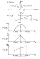
- FIG. 2a represents an example of an illumination pattern E received by the photodetectors of a line 9 of the matrix, associated with the dispersed wavelength ⁇ 0 . x ( ⁇ 0 ) locates the position of the photodetectors in this line.
- the illumination E is in arbitrary unit (au).
- the curve of FIG. 2a is initially defined by discrete points corresponding to each photodetector of line 9. It is advantageously completed by interpolation, in a manner known to those skilled in the art, to obtain a continuous curve.
- FIG. 2b illustrates an example of variation of the optical path length difference ⁇ L as a function of the position x ( ⁇ 0 ) of the image S D ( ⁇ 0 ) along the line 9 associated with ⁇ 0 .
- This variation is linear for mirrors 32 and 33 planes.
- the slope of this variation is equal to the angle ⁇ of inclination of the mirror 33, multiplied by the magnification G of the intermediate optics 10 and the dispersive system 6 between the mirrors 32/33 and the matrix 8.
- a photodetector located 20 millimeters from the center line MM (FIG. 1b) of the matrix 8 parallel to the direction D4 corresponds to a difference in optical path length ⁇ L of 20 microns.
- the inverse Fourier transform is calculated with respect to the optical path length difference ⁇ L, evaluated for each selected photodetector.
- the conjugate variables when calculating the inverse Fourier transformation are ⁇ L and 2 ⁇ / ⁇ 1 .
- a raw spectrum segment indicating an intensity I for wavelength values ⁇ 1 of said raw spectrum segment is then obtained.
- the wavelength values ⁇ 1 are distributed around the dispersed wavelength ⁇ 0 associated with the line 9 considered of the matrix 8.
- FIG. 2c represents, in an approximate manner, a gross spectrum segment thus obtained.
- the extension of the raw spectrum segment on both sides of ⁇ 0 is for example approximately ⁇ 30 nanometers.
- FIG. 2d An example of an apparatus function for a line 9 of the matrix 8 is illustrated in FIG. 2d.
- the diagram of this figure having for abscissa the wavelength ⁇ 1 , has a triangular shape centered on the value of ⁇ 0 . This shape results from the coincidence between the slot 4 and the line 9 of the matrix 8 associated with the dispersed wavelength ⁇ 0 .
- the intensity I read on the raw spectrum segment (FIG. 2c) is then divided for each wavelength value ⁇ 1 by the instrument response value corresponding to the same wavelength ⁇ 1 (FIG. ).
- a corrected spectrum segment T (FIG. 2e) is then obtained, which indicates a corrected intensity I corr for each wavelength value ⁇ 1 .
- the corrected spectrum segments obtained for each matrix line 9 are grouped in a grouping spectral diagram (FIG. 2f). This grouping is performed by positioning on a single wavelength axis the length values of scattered waves ⁇ 0 , ⁇ 0 ', ⁇ 0 ", ..., and carrying around each of them the corresponding corrected spectrum segment T, T', T", .... Possibly interpolation or correction It can be done between two segments of successive corrected spectra, in order to obtain a global spectral intensity curve free of reconstruction artifacts.
- the spectral resolution of the spectrophotometer is otherwise limited by the size of the mirrors 32 and 33 parallel to the main direction D1. But an increase in the size of the mirrors 32 and 33 results in a significant increase in the cost, weight and bulk of the whole spectrophotometer. An improvement of the spectrophotometer Previous is now described, which improves the spectral resolution.
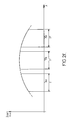
- one of the two mirrors 32 or 33 is plane, and the other mirror, for example the mirror 33, is ladder mirror type, as shown in Figure 3a.
- a mirror with a ladder is formed of reflective flat strips 330, rectangular and juxtaposed in a direction D.
- Each band has a width d of 200 micrometers, for example, and a length equal to the size of the mirror 33 parallel to the axis B-B.
- Each band 330 is parallel to a plane of reference P of the eclamp mirror, and is shifted with respect to the plane P of a respective distance measured perpendicular to the reference plane.
- the gap e between the distances on the plane P of two successive bands according to the direction D is, for example, 1 micrometer.
- the mirror 33 comprises for example 10 bands 330.
- the plane mirror 32 is maintained in the position perpendicular to the direction D0 'described above, within the interferometer 3.
- the mirror ladder is placed at the tilting axis B-B, and is oriented initially so that the direction D related to the mirror is parallel to the direction D1. It is then inclined along the axis B-B of an angle ⁇ with respect to the direction D1, between 0.2 degrees and 5 degrees, for example.
- FIG. 3b illustrates, in a manner analogous to FIG. 2b, the variations the difference in optical path length for a spectrophotometer according to Figure 1a which incorporates a plane mirror 32 and a mirror 33 echelette.
- the curve obtained is discontinuous: it is formed of successive steps respectively associated with the strips 330. Each step has a slope per ratio to the abscissa axis equal to ⁇ x G, a height equal to 2 x e and a length along the abscissa axis equal to d x G.
- the offsets bands 330 of the mirror 33 generates a subsampling of the values of ⁇ L: the values of the optical path length difference corresponding to lightings received by photodetectors only correspond to one part of all possible values.
- this subsampling results in a folding of spectrum segments obtained. This behavior, well known to the man of is a filtering effect due to the reduced width of bands 330.
- the second intermediate beam thus corresponds to a second interference pattern of the third and fourth reflected secondary beams and grouped.
- This second interference figure has a direction main variation of a second difference in optical path length substantially perpendicular to the direction of propagation of the second beam intermediate.
- the second interferometer is also adjustable so that a second image of the source S is formed inside the second interferometer, substantially at the third and fourth mirrors, and so that the second image moves parallel to the main direction of the second interference figure during a displacement of the scanning device 1 .
- the first cylindrical mirror is arranged to confer on the third secondary beam, after reflection on the first cylindrical mirror, a convergent beam and parallel beam configuration according to respective directions perpendicular to the direction of propagation of the third secondary beam.
- the second cylindrical mirror is arranged to to give the third reflected secondary beam, after reflection on the second cylindrical mirror, a divergent spherical beam configuration.
- the second interferometer is oriented so that the direction principal of the second interference figure is substantially parallel to a direction conjugated with the direction of the great length of the slot 4.
- the second interferometer, the second dispersive system and the second matrix of photodetectors form an additional optical channel arranged in parallel to the interferometer 3, the dispersive system 6 and the matrix 8.
- a main separator is arranged in the primary beam F2, which sends a first portion of the beam F2 into the interferometer 3, and a second part of the beam F2 in the second interferometer.
- the separator principal may, in particular, be of the semi-reflecting blade type.
- the second interferometer is integrated with interferometer 3, the second dispersive system is confused with the dispersive system 6, and the second matrix of photodetectors is juxtaposed to the matrix 8 so the lines of the second matrix are located in line with lines 9 of the matrix 8.
- the second matrix and the matrix 8 are grouped into a single matrix, still referred to as matrix 8, having lines 9 of increased length. The second separation device and the second device grouping can then be confused with the separation device 31.
- FIG. 4 is an optical diagram of the interferometer 3 thus obtained. For the sake of clarity, this scheme is broken down in the D1 direction, and both axes 100 and 200 direction D0 must be read as being merged.
- the interferometer 3 is divided into two parts P1 and P2 juxtaposed according to the direction D1.
- the part P1 is that described above in relation to the figure 1a, including the mirrors 32 and 33, and a first half of the device 31.
- a second half of the separation device 31 is extends symmetrically in the P2 part of the interferometer 3.
- the mirrors 32 and 33 are limited in part P1.
- the primary beam F2 passes successively from the P1 part to the P2 part.
- the operation of the interferometer when the primary beam F2 is in the P1 part has already been described.
- the plane mirror 35 and the convex cylindrical mirrors 37 and 38 have a function identical to that of the mirror 32.
- the mirror 36 and the flat mirrors 39 and 40 have a function identical to that of the mirror 33.
- the mirror 36 may be identical to the mirror 33, being, for example, the ladder type.
- the separation device 31 separates the primary beam F2 into two secondary beams F8 and F9 respectively incident on the mirrors 37 and 39.
- the secondary beams F8 and F9 are shifted according to the main direction D1 with respect to the secondary beams F3 and F4.
- a device not shown in FIG. 4 can be arranged at the input of the P2 part of the interferometer, to shift the beams F8 and F9, so that these beams pass respectively to outside the mirrors 35 and 36 before being reflected by the mirrors 37 and 39, respectively.
- the secondary beam F8 becomes the beam F10, reflected by the mirror 38 so as to be redirected to the separation and grouping mechanism 31.
- the secondary beam F9 becomes the beam F11, reflected by the mirror 40 so as to be also redirected to the device 31.
- the device 31 then regroups, in the P2 part of the interferometer, the beams F10 and F11 in a second intermediate beam F12 which corresponds to the second figure interference, distinct from the interference pattern of the intermediate beam F7.
- the mirrors 32, 33, 35 and 36 as well as the two cylindrical mirrors convex 37 and 38 and the two plane mirrors 39 and 40 are arranged so that the main direction of the second interference figure is merged with or is parallel to the main direction D1 of the interference pattern corresponding to the intermediate beam F7.
- the second intermediate beam F12 passes through the dispersion system 6 in the same way as the intermediate beam F7, and forms, like the latter, an image of the source S.
- the positions of the mirrors 32 and 33 are adjusted in relation to those mirrors 35 and 36 so that the optical paths between, on the one hand, the mirrors 32 or 33 and the matrix 8, and on the other hand the mirrors 35 or 36 and the matrix 8, have substantially identical lengths, with the effects interferential close.
- the beams F7 and F12 then form successive images S D ( ⁇ ) which move on the same line 9 of photodetectors during a displacement of the scanning device 1.
- Each line 9 of photodetectors then corresponds to a first half of its length. to the optical path length difference variation in the interferometer portion 1, and for a second half of its length to the optical path length difference variation in the P2 portion of the interferometer.
- the respective photodetectors of the first and second halves of length of the lines 9 detect illuminations corresponding to two interference figures in quadrature.
- the recording of the illuminations of these two quadrature interference patterns are then combined with the calculation of the inverse Fourier transformation, in a manner known per se. This combination avoids the folding artefact of the spectrum segments.
- the slot 4 can also be arranged in the primary beam F2, in one of the secondary beams F3 / F8 or F4 / F9, in one of the secondary beams reflective F5 / F10 or F6 / F11, or in the intermediate beam F7 / F12.
- a common continuous device of shifting of the beams along the axis B-B can also be arranged at the input of the interferometer 3, in the two parts P1 and P2.
- Such a device makes it possible to shift the secondary beams F3-F6 so that they accommodate, in the part P1 of the interferometer, folded configurations similar to those secondary beams F8-F11 in the P2 part of the interferometer.
Landscapes
- Physics & Mathematics (AREA)
- Spectroscopy & Molecular Physics (AREA)
- General Physics & Mathematics (AREA)
- Spectrometry And Color Measurement (AREA)
Applications Claiming Priority (2)
| Application Number | Priority Date | Filing Date | Title |
|---|---|---|---|
| FR0309443A FR2858404B1 (fr) | 2003-07-31 | 2003-07-31 | Spectrophotometre comprenant un interferometre et un systeme dispersif |
| FR0309443 | 2003-07-31 |
Publications (3)
| Publication Number | Publication Date |
|---|---|
| EP1503192A1 true EP1503192A1 (de) | 2005-02-02 |
| EP1503192B1 EP1503192B1 (de) | 2013-05-01 |
| EP1503192B8 EP1503192B8 (de) | 2013-07-03 |
Family
ID=33523032
Family Applications (1)
| Application Number | Title | Priority Date | Filing Date |
|---|---|---|---|
| EP20040291708 Expired - Lifetime EP1503192B8 (de) | 2003-07-31 | 2004-07-06 | Spektrophotometer mit einem Interferometer und einem dispersiven System |
Country Status (2)
| Country | Link |
|---|---|
| EP (1) | EP1503192B8 (de) |
| FR (1) | FR2858404B1 (de) |
Cited By (6)
| Publication number | Priority date | Publication date | Assignee | Title |
|---|---|---|---|---|
| EP1793213A1 (de) * | 2005-12-01 | 2007-06-06 | Astrium Sas | Abtastspektrometer mit Interferometer |
| US7646361B2 (en) | 2004-11-19 | 2010-01-12 | Lg Electronics Inc. | Plasma display apparatus and driving method thereof |
| CN102072768A (zh) * | 2010-10-26 | 2011-05-25 | 中国科学院化学研究所 | 一种二维红外光谱装置及其光学干涉仪 |
| CN110501289A (zh) * | 2018-05-16 | 2019-11-26 | 中国科学院西安光学精密机械研究所 | 一种基于数字微镜阵列dmd的光谱展宽方法及装置 |
| CN110501074A (zh) * | 2018-05-16 | 2019-11-26 | 中国科学院西安光学精密机械研究所 | 高通量宽谱段高分辨率的相干色散光谱成像方法及装置 |
| CN115629469A (zh) * | 2022-09-22 | 2023-01-20 | 中国科学院长春光学精密机械与物理研究所 | 一种大型望远镜消旋消色散标定及控制方法和系统 |
Families Citing this family (1)
| Publication number | Priority date | Publication date | Assignee | Title |
|---|---|---|---|---|
| FR2894332B1 (fr) | 2005-12-01 | 2014-12-12 | Eads Astrium Sas | Spectrophotometre a large fente d'entree |
Citations (3)
| Publication number | Priority date | Publication date | Assignee | Title |
|---|---|---|---|---|
| US4538910A (en) * | 1982-09-30 | 1985-09-03 | Laser Precision Corporation | Dual beam fourier spectrometer |
| US4681445A (en) * | 1984-07-18 | 1987-07-21 | U.S. Philips Corporation | Interferometer |
| US6351307B1 (en) * | 1999-02-23 | 2002-02-26 | The Regents Of The University Of California | Combined dispersive/interference spectroscopy for producing a vector spectrum |
-
2003
- 2003-07-31 FR FR0309443A patent/FR2858404B1/fr not_active Expired - Fee Related
-
2004
- 2004-07-06 EP EP20040291708 patent/EP1503192B8/de not_active Expired - Lifetime
Patent Citations (3)
| Publication number | Priority date | Publication date | Assignee | Title |
|---|---|---|---|---|
| US4538910A (en) * | 1982-09-30 | 1985-09-03 | Laser Precision Corporation | Dual beam fourier spectrometer |
| US4681445A (en) * | 1984-07-18 | 1987-07-21 | U.S. Philips Corporation | Interferometer |
| US6351307B1 (en) * | 1999-02-23 | 2002-02-26 | The Regents Of The University Of California | Combined dispersive/interference spectroscopy for producing a vector spectrum |
Cited By (10)
| Publication number | Priority date | Publication date | Assignee | Title |
|---|---|---|---|---|
| US7646361B2 (en) | 2004-11-19 | 2010-01-12 | Lg Electronics Inc. | Plasma display apparatus and driving method thereof |
| EP1793213A1 (de) * | 2005-12-01 | 2007-06-06 | Astrium Sas | Abtastspektrometer mit Interferometer |
| FR2894333A1 (fr) * | 2005-12-01 | 2007-06-08 | Eads Astrium Sas Soc Par Actio | Spectrophotometre a echantillonnage comprenant un interferometre |
| US7440107B2 (en) | 2005-12-01 | 2008-10-21 | Astrium Sas | Sampling spectrophotometer comprising an interferometer |
| CN102072768A (zh) * | 2010-10-26 | 2011-05-25 | 中国科学院化学研究所 | 一种二维红外光谱装置及其光学干涉仪 |
| CN110501289A (zh) * | 2018-05-16 | 2019-11-26 | 中国科学院西安光学精密机械研究所 | 一种基于数字微镜阵列dmd的光谱展宽方法及装置 |
| CN110501074A (zh) * | 2018-05-16 | 2019-11-26 | 中国科学院西安光学精密机械研究所 | 高通量宽谱段高分辨率的相干色散光谱成像方法及装置 |
| CN110501074B (zh) * | 2018-05-16 | 2023-05-26 | 中国科学院西安光学精密机械研究所 | 高通量宽谱段高分辨率的相干色散光谱成像方法及装置 |
| CN110501289B (zh) * | 2018-05-16 | 2023-05-26 | 中国科学院西安光学精密机械研究所 | 一种基于数字微镜阵列dmd的光谱展宽方法及装置 |
| CN115629469A (zh) * | 2022-09-22 | 2023-01-20 | 中国科学院长春光学精密机械与物理研究所 | 一种大型望远镜消旋消色散标定及控制方法和系统 |
Also Published As
| Publication number | Publication date |
|---|---|
| FR2858404B1 (fr) | 2006-01-13 |
| EP1503192B1 (de) | 2013-05-01 |
| EP1503192B8 (de) | 2013-07-03 |
| FR2858404A1 (fr) | 2005-02-04 |
Similar Documents
| Publication | Publication Date | Title |
|---|---|---|
| US8792105B2 (en) | Interferometer with variable optical path length reference mirror using overlapping depth scan signals | |
| EP4042098B1 (de) | Vorrichtung und verfahren zur bildmessung und interferometrie | |
| EP3980715A1 (de) | Verfahren und vorrichtung zum messen von schnittstellen eines optischen elements | |
| FR2726641A1 (fr) | Procede et dispositif pour profiler des surfaces en utilisant une optique de diffraction | |
| EP2368098A1 (de) | Bildgebungsspektrometer des dyson-typs mit verbesserter bildqualität und geringen verzerrungen | |
| EP4214463A1 (de) | Vorrichtung und verfahren zur vermessung von schnittstellen eines optischen elements | |
| EP1503192B1 (de) | Spektrophotometer mit einem Interferometer und einem dispersiven System | |
| US11300799B2 (en) | Generally v-shaped interferometer formed from beamsplitter deployed between geometrically similar prisms | |
| FR2555323A1 (fr) | Perfectionnements aux dispositifs de filtrage optique | |
| EP3030867B1 (de) | Spektrometer mit einer vielzahl von beugungsgittern | |
| EP2554941B1 (de) | Optisches Messsystem der Ausrichtung eines Helms mit Hilfe von Retroreflektoren und telezentrischer Emissionsoptik | |
| EP3194916B1 (de) | Wellenfrontanalysator und verfahren zur bestimmung von differenzen in einer amplitude und neigung zwischen mehreren lichtstrahlen | |
| KR102903313B1 (ko) | 필터 요소를 갖는 광학계 | |
| EP1793212B1 (de) | Spektrophotometer mit breiter Eintrittsspalte | |
| EP2473824B1 (de) | Feldkompensiertes interferometer | |
| EP2309236B1 (de) | Teleskop mit Blickfeldkomprimierung für atmosphärische Beobachtung | |
| FR2513375A1 (fr) | Interferometre a basculement invariable et a miroirs plans | |
| FR2936323A1 (fr) | Telescope de type korsch a miroirs de renvoi. | |
| EP1793213B9 (de) | Abtastspektrometer mit Interferometer | |
| EP1141668B1 (de) | Vorrichtung zum spektralen abblenden in einem optischen bildsensor | |
| WO2026003442A1 (fr) | Procede de correction de mesures d'un element optique | |
| FR2876793A1 (fr) | Spectrometre statique par transformee de fourier du type coin d'air |
Legal Events
| Date | Code | Title | Description |
|---|---|---|---|
| PUAI | Public reference made under article 153(3) epc to a published international application that has entered the european phase |
Free format text: ORIGINAL CODE: 0009012 |
|
| AK | Designated contracting states |
Kind code of ref document: A1 Designated state(s): AT BE BG CH CY CZ DE DK EE ES FI FR GB GR HU IE IT LI LU MC NL PL PT RO SE SI SK TR |
|
| AX | Request for extension of the european patent |
Extension state: AL HR LT LV MK |
|
| 17P | Request for examination filed |
Effective date: 20050603 |
|
| AKX | Designation fees paid |
Designated state(s): DE GB IT NL |
|
| RAP1 | Party data changed (applicant data changed or rights of an application transferred) |
Owner name: EADS ASTRIUM SAS |
|
| 17Q | First examination report despatched |
Effective date: 20050715 |
|
| GRAP | Despatch of communication of intention to grant a patent |
Free format text: ORIGINAL CODE: EPIDOSNIGR1 |
|
| GRAS | Grant fee paid |
Free format text: ORIGINAL CODE: EPIDOSNIGR3 |
|
| GRAA | (expected) grant |
Free format text: ORIGINAL CODE: 0009210 |
|
| AK | Designated contracting states |
Kind code of ref document: B1 Designated state(s): DE GB IT NL |
|
| REG | Reference to a national code |
Ref country code: GB Ref legal event code: FG4D Free format text: NOT ENGLISH |
|
| RAP2 | Party data changed (patent owner data changed or rights of a patent transferred) |
Owner name: ASTRIUM SAS |
|
| REG | Reference to a national code |
Ref country code: DE Ref legal event code: R096 Ref document number: 602004041954 Country of ref document: DE Effective date: 20130627 |
|
| REG | Reference to a national code |
Ref country code: NL Ref legal event code: T3 |
|
| PLBE | No opposition filed within time limit |
Free format text: ORIGINAL CODE: 0009261 |
|
| STAA | Information on the status of an ep patent application or granted ep patent |
Free format text: STATUS: NO OPPOSITION FILED WITHIN TIME LIMIT |
|
| 26N | No opposition filed |
Effective date: 20140204 |
|
| REG | Reference to a national code |
Ref country code: DE Ref legal event code: R097 Ref document number: 602004041954 Country of ref document: DE Effective date: 20140204 |
|
| PGFP | Annual fee paid to national office [announced via postgrant information from national office to epo] |
Ref country code: NL Payment date: 20190617 Year of fee payment: 16 |
|
| PGFP | Annual fee paid to national office [announced via postgrant information from national office to epo] |
Ref country code: IT Payment date: 20190723 Year of fee payment: 16 Ref country code: DE Payment date: 20190711 Year of fee payment: 16 |
|
| PGFP | Annual fee paid to national office [announced via postgrant information from national office to epo] |
Ref country code: GB Payment date: 20190719 Year of fee payment: 16 |
|
| REG | Reference to a national code |
Ref country code: DE Ref legal event code: R119 Ref document number: 602004041954 Country of ref document: DE |
|
| REG | Reference to a national code |
Ref country code: NL Ref legal event code: MM Effective date: 20200801 |
|
| GBPC | Gb: european patent ceased through non-payment of renewal fee |
Effective date: 20200706 |
|
| PG25 | Lapsed in a contracting state [announced via postgrant information from national office to epo] |
Ref country code: GB Free format text: LAPSE BECAUSE OF NON-PAYMENT OF DUE FEES Effective date: 20200706 Ref country code: NL Free format text: LAPSE BECAUSE OF NON-PAYMENT OF DUE FEES Effective date: 20200801 |
|
| PG25 | Lapsed in a contracting state [announced via postgrant information from national office to epo] |
Ref country code: DE Free format text: LAPSE BECAUSE OF NON-PAYMENT OF DUE FEES Effective date: 20210202 |
|
| PG25 | Lapsed in a contracting state [announced via postgrant information from national office to epo] |
Ref country code: IT Free format text: LAPSE BECAUSE OF NON-PAYMENT OF DUE FEES Effective date: 20200706 |