EP1503196A1 - Procédé et installation pour la mesure du couple d'entrainement d'un moteur électrique avec une boíte de vitesse - Google Patents
Procédé et installation pour la mesure du couple d'entrainement d'un moteur électrique avec une boíte de vitesse Download PDFInfo
- Publication number
- EP1503196A1 EP1503196A1 EP04019235A EP04019235A EP1503196A1 EP 1503196 A1 EP1503196 A1 EP 1503196A1 EP 04019235 A EP04019235 A EP 04019235A EP 04019235 A EP04019235 A EP 04019235A EP 1503196 A1 EP1503196 A1 EP 1503196A1
- Authority
- EP
- European Patent Office
- Prior art keywords
- torque
- torque sensor
- connecting webs
- motor
- output
- Prior art date
- Legal status (The legal status is an assumption and is not a legal conclusion. Google has not performed a legal analysis and makes no representation as to the accuracy of the status listed.)
- Granted
Links
Images


Classifications
-
- G—PHYSICS
- G01—MEASURING; TESTING
- G01L—MEASURING FORCE, STRESS, TORQUE, WORK, MECHANICAL POWER, MECHANICAL EFFICIENCY, OR FLUID PRESSURE
- G01L3/00—Measuring torque, work, mechanical power, or mechanical efficiency, in general
- G01L3/02—Rotary-transmission dynamometers
- G01L3/14—Rotary-transmission dynamometers wherein the torque-transmitting element is other than a torsionally-flexible shaft
- G01L3/1407—Rotary-transmission dynamometers wherein the torque-transmitting element is other than a torsionally-flexible shaft involving springs
- G01L3/1428—Rotary-transmission dynamometers wherein the torque-transmitting element is other than a torsionally-flexible shaft involving springs using electrical transducers
- G01L3/1457—Rotary-transmission dynamometers wherein the torque-transmitting element is other than a torsionally-flexible shaft involving springs using electrical transducers involving resistance strain gauges
-
- B—PERFORMING OPERATIONS; TRANSPORTING
- B25—HAND TOOLS; PORTABLE POWER-DRIVEN TOOLS; MANIPULATORS
- B25J—MANIPULATORS; CHAMBERS PROVIDED WITH MANIPULATION DEVICES
- B25J13/00—Controls for manipulators
- B25J13/08—Controls for manipulators by means of sensing devices, e.g. viewing or touching devices
- B25J13/085—Force or torque sensors
Definitions
- the invention relates to a method and a device for Measuring the output torque of an electric motor with a this downstream transmission and this device usable torque sensors.
- Torque sensors commonly called torque measuring shafts in Output strands installed.
- torque measuring shafts in Output strands installed.
- the installation of such torque measuring shafts in stripping is only very expensive possible and requires a high cost and a high Effort in terms of interface customization, because several electromechanical components mostly different Manufacturers must be combined.
- the object of the invention is a torque sensor so in a motor-gear unit to accommodate that of any Disturbances and other influences as little as possible impaired, the output torque as accurately as possible reproducing measured value of high quality is obtained.
- this object is achieved in a method for Determining an output torque of an electric motor with Subordinate transmission by the features of claim 1 and in a device for carrying out the method solved by the features of claim 2. Further are at the device usable for performing the method Torque sensors specified.
- a dynamic motor torque M disturbance torque is measured according to the invention by means of one of the torque sensors according to the invention, which is fixedly supported with a ring gear of the transmission, for example in the form of a harmonic drive or planetary gear and thus directly to the transmission ring gear connected is.
- the gear ring gear and the torque sensor can be made in one piece.
- the stationary support over a stationary housing takes place, supports the ring gear of the transmission on this stationary housing, so that power flow from the motor shaft via the gearbox to the motor housing and thus does not go via the torque sensor.
- the torque sensor Since according to the invention, the stationary support over a stationary housing takes place, supports the ring gear of the transmission on this stationary housing, so that power flow from the motor shaft via the gearbox to the motor housing and thus does not go via the torque sensor.
- the inventive solution it comes to a different effect.
- the engine starts and thus a speed change takes place, there is a kind of "jerk" on the outside of the motor housing, which is caused by the inertia of the motor shaft, and which is detected by the torque sensor.
- the disturbing dynamic engine torque M disturbance torque is measured by the integrated sensor, as set forth above, as a "jerk" is perceptible.
- ⁇ n denotes a speed change
- ⁇ t a time interval
- ⁇ ⁇ a speed change of the motor shaft J the rotational mass inertia of the motor shaft.
- the torque sensors provided according to the invention a disc-shaped design have a significantly lower Height as known from the prior art torque sensors. Furthermore, in the invention, both the integrated Torque sensor as well as the transmission and the engine of one Surrounded by fixed housing, so that the above cited important components not only against environmental influences of any kind but also from dirt and the like and protected against electromagnetic radiation.
- an output torque becomes exact receive corresponding measurement signals, through which at introduction in a regulation of the engine torque whose precision is significantly improved.
- the installation position of the torque sensor for example, in a servo drive unit of great importance with regard to the quality of the Signal.
- the lines for transmitting measured by a torque sensor Signals are led on the motor side, so that a sensor operation is realized with multi-turn.
- integrable torque sensor embodiments have a very compact design, is with appropriate integration of the respective torque sensor in a drive gear unit, the moment of inertia not increased or in other words, it is not larger than with a corresponding drive unit, in which no torque sensor is integrated. Furthermore is by integrating a torque sensor into a drive unit an easy-to-use for the user Torque interface created and given.
- Fig. 1 is a unit of a motor 90 and a transmission 91 housed in a stationary housing 92, the supported by a schematically indicated housing part 92a is.
- a torque sensor 1 or 2 is fixed between Housing 92 and the gear 91 and the ring gear of the transmission 91 provided.
- Fig.1 is schematic a storage 94 indicated.
- the invention measures between the housing 92 and the Gear 91 sensor housed an output torque and In addition, a disturbing dynamic motor torque, the at a change in speed occurs and a "jerk" of the motor housing leads. From one to the one described above Way accommodated torque sensor 1 or 2 are no static motor torques and thus will not be the Frictional torque of the motor shaft bearing measured, which is not calculable and thus can not be compensated.
- Fig.2 the essential part of another embodiment represented according to the invention.
- the Harmonic Drive Transmission 95 is over in the outer bearing 10 a bearing provided 94 stored.
- the torque sensors 1 or 2 are one of the torque sensors 1 or 2 intended.
- the torque sensor 1 or 2 and the ring gear 98 of the harmonic drive transmission 95 also in difference formed integrally to the illustration in Figure 9 be.
- Fig.3a and 3b are each in perspective Front and back of a first embodiment of a Torque sensor shown which as a monolithic, disc-shaped receiving part 1 is formed, whose Top one divided into contiguous sections, plane surface is.
- the receiving part 1 consists of an inner flange 10 with a Number of first force introduction points 12, an outer flange 11 with a generally larger number of second ones Force introduction points 13 and four between the two Flanges 10 and 11 formed, radially extending Connecting webs 14 with mechanically weakened sections in the form of underside recesses 15th
- the underside recesses 15 are respectively, as the perspective view of the back in Figure 3b or the sectional view in Figure 5 and the illustration in Figure 4 can be seen, optimized to the effect that they are preferably kidney-shaped and by a thin membranous Conclusion 15a (Figure 5) are completed with respect to the top.
- the upper side of the membrane-like closure 15a (FIG. 5) and thus of the recess is a planar surface on which measuring sensors, for example strain gauges 6 1 (FIG. 3 a) are applied.
- FIGS each weakened by a recess 15 sections of Connecting webs 14 has a substantially U-shaped cross-section. Furthermore, the transition from the flat underside the membrane-like conclusion 15a of the respective recess 15 in the recess bottom approximately perpendicular Wall portions 15c as a circumferential rounding or grooving 15b formed. This results in a lower Material load in this area and on top of that a more even Voltage curve, which in turn is very beneficial Way to affect the life of a torque sensor.
- the membrane-like termination 15a is thus of webs (wall areas) with different wall thicknesses and thereby surrounded with elastic and less elastic areas, why protruding from a kidney-shaped recess is spoken.
- This also has the consequence that this at a Torque load is yielding, while at an axial load or tilting load is stiff due to a tilting moment. Furthermore, high stresses or strains occur in the membranous Conclusion 15a thus exclusively only at the measuring torques.
- strain gauges 6 1 are mirror images of two diagonally opposite connecting webs 14 also again applied at 45 ° to a fictitious, radially extending center line of the respective connecting web 14.
- each connecting bridge 14 two measuring spokes with variable cross section each with a flat outer application surface for application formed by strain gauges.
- adjacent connecting webs 14 provided cutouts 16 lugs 17 formed, which is approximately in the middle the respective section 16 from the inside of the outer flange 11 protrude inward.
- approaches 17 may be electronic hardware, for example in the form of an analogue amplifier for amplifying the determined measured values and a subordinate to the amplifier analog-to-digital converter and the actual evaluation directly on / on the mounted monolithic receiving part 1 of the torque sensor become.
- the torque sensor again as a monolithic disc-shaped receiving part 2 formed with a flat top.
- the receiving part 2 again consists of a annular inner flange 20 with first force application points 22, from an annular outer flange 21 with second force introduction points 23 and four between the two flanges formed, radially extending connecting webs 24th
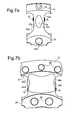
- the outer surfaces 24a (FIG. 7a) and 24'a (FIG. 7b) aligned perpendicular to the surface of the receiving part 2 and extending in the radial direction are the respective connecting webs 24 and 24 'as formed flat surfaces on which appropriately aligned transducers 6 1 are applied.
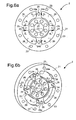
- the approximately radially oriented wall regions 25c and 25'c of the respective cutouts 25 and 25 'of the connecting webs 24 and 24' have a variable cross section, which in turn is elastic and less elastic and so that stiffer areas alternate.
- cutouts 25 in Fig.6a, 6b and FIG. 7 a shows the elastic regions approximately in the middle region the split in two spokes connecting webs 24th or 24a, while the less elastic and thus Stiffer areas in the transitions from the connecting webs 24 and 24 'to the inner flange 20 and the outer flange 21 are located.
- Fig. 7b corresponds to the different ones Wall thicknesses and thus the elastic and less elastic portions of those described in detail above Embodiment in Fig.4.
- the only difference is in that it is in Fig.7b one of the Oberzur Bottom of the receiving part through cutout 25 ' acts while in Figure 4, a recess 15 with a thin membranous closure 15a is provided.
- a common feature of the embodiments in FIGS. 6a to 7b is that the application surfaces are planar and in each case formed on the outer sides of the connecting webs 24, 24 'as plane-parallel surfaces for applying strain gauges 6 1 .
- the loadable cross-section of the two measuring spokes of each connecting web 24 or 24 'located under the application surfaces is variable.
- each Connecting web formed Meßspeichen Due to the non-constant cross section of the two in each Connecting web formed Meßspeichen results in a load a more favorable bend or a beneficial Bend line, so even in this case the placement
- the strain gauges are not quite as accurate as in the Be made hitherto known embodiments must, and thus the application of the strain gauges can be done faster and therefore cheaper. Further is a misplacement hardly possible, so that also a given greater reliability in terms of operation is.
- the two outer surfaces of each Connecting web 24, 24 'formed two measuring spokes respectively is a flat application surface and on top of that the two application surfaces essentially plane-parallel when applying the strain gauges, to apply the required contact pressure, for example simple screw clamps are used.
Landscapes
- Engineering & Computer Science (AREA)
- Physics & Mathematics (AREA)
- General Physics & Mathematics (AREA)
- Human Computer Interaction (AREA)
- Robotics (AREA)
- Mechanical Engineering (AREA)
- Force Measurement Appropriate To Specific Purposes (AREA)
- Retarders (AREA)
Applications Claiming Priority (7)
| Application Number | Priority Date | Filing Date | Title |
|---|---|---|---|
| DE10217016 | 2002-04-12 | ||
| DE10217015 | 2002-04-12 | ||
| DE10217016 | 2002-04-12 | ||
| DE10304359A DE10304359A1 (de) | 2002-04-12 | 2003-02-03 | Drehmomentsensor in der Form eines monolithischen Aufnahmeteils |
| DE10304359 | 2003-02-03 | ||
| DE10217015 | 2003-04-12 | ||
| EP03008566A EP1353159B1 (fr) | 2002-04-12 | 2003-04-14 | Capteur de couple monolithique |
Related Parent Applications (2)
| Application Number | Title | Priority Date | Filing Date |
|---|---|---|---|
| EP03008566.6 Division | 2003-04-14 | ||
| EP03008566A Division EP1353159B1 (fr) | 2002-04-12 | 2003-04-14 | Capteur de couple monolithique |
Publications (2)
| Publication Number | Publication Date |
|---|---|
| EP1503196A1 true EP1503196A1 (fr) | 2005-02-02 |
| EP1503196B1 EP1503196B1 (fr) | 2005-12-28 |
Family
ID=29550921
Family Applications (1)
| Application Number | Title | Priority Date | Filing Date |
|---|---|---|---|
| EP04019235A Expired - Lifetime EP1503196B1 (fr) | 2002-04-12 | 2003-04-14 | Procédé et installation pour la mesure du couple d'entrainement d'un moteur électrique avec une boíte de vitesse |
Country Status (2)
| Country | Link |
|---|---|
| EP (1) | EP1503196B1 (fr) |
| DE (1) | DE10317304A1 (fr) |
Cited By (9)
| Publication number | Priority date | Publication date | Assignee | Title |
|---|---|---|---|---|
| DE102015119424A1 (de) | 2015-11-11 | 2017-05-11 | Reis Gmbh & Co. Kg Maschinenfabrik | Verfahren zum Bearbeiten zumindest eines Werkstücks |
| CN107991094A (zh) * | 2017-12-17 | 2018-05-04 | 成都育芽科技有限公司 | 一种工业机器人用谐波减速机性能试验方法 |
| WO2019171810A1 (fr) * | 2018-03-08 | 2019-09-12 | 日本電産コパル電子株式会社 | Capteur de couple |
| DE102018213452A1 (de) * | 2018-08-09 | 2020-02-13 | Kuka Deutschland Gmbh | Roboterarm mit wenigstens einem Gelenkmomentsensor |
| CN111152258A (zh) * | 2019-12-12 | 2020-05-15 | 中山市北京理工大学研究院 | 一种具有力感知功能的机械集成关节 |
| WO2021104948A1 (fr) * | 2019-11-30 | 2021-06-03 | Agile Robots AG | Joint de bras mécanique |
| CN113715014A (zh) * | 2021-09-22 | 2021-11-30 | 哈尔滨工业大学 | 适用于深海机器人的大力矩一体化驱动关节 |
| JP2022010550A (ja) * | 2020-06-29 | 2022-01-17 | トヨタ自動車株式会社 | 力覚センサ |
| JP2022019838A (ja) * | 2018-03-08 | 2022-01-27 | 日本電産コパル電子株式会社 | トルクセンサ |
Families Citing this family (8)
| Publication number | Priority date | Publication date | Assignee | Title |
|---|---|---|---|---|
| AT7835U1 (de) * | 2004-05-28 | 2005-09-26 | Siemens Ag Oesterreich | Elektrische maschine mit drehmomentmesseinrichtung |
| DE102019112146B3 (de) * | 2019-05-09 | 2020-09-10 | Schaeffler Technologies AG & Co. KG | Vorrichtung zum Messen eines Drehmoments und Spannungswellengetriebe mit dieser Vorrichtung |
| DE102019120344B4 (de) * | 2019-07-26 | 2023-10-12 | Deutsches Zentrum für Luft- und Raumfahrt e.V. | Aktuatorvorrichtung, Robotergelenkvorrichtung und Roboter |
| EP3896416B1 (fr) * | 2020-04-16 | 2025-08-13 | TE Connectivity Sensors France | Capteur de couple |
| WO2021219199A1 (fr) * | 2020-04-28 | 2021-11-04 | Rethink Robotics Gmbh | Dispositif d'entraînement, bras rototique et procédé de mesure de couple |
| DE102021205369B3 (de) | 2021-05-27 | 2022-09-15 | Zf Friedrichshafen Ag | Prüfstand für einen Antriebsstrang eines Kraftfahrzeugs |
| DE102021116857A1 (de) | 2021-06-30 | 2023-01-05 | Minebea Mitsumi Inc. | Drehmomentsensor |
| CN115451082B (zh) * | 2022-10-18 | 2025-07-01 | 上海非夕机器人科技有限公司 | 谐波减速器、测量谐波减速器中扭矩的方法、及机器人 |
Citations (8)
| Publication number | Priority date | Publication date | Assignee | Title |
|---|---|---|---|---|
| US4281538A (en) * | 1973-05-14 | 1981-08-04 | Thor Power Tool Company | Transducer for indicating torque |
| US5010970A (en) * | 1988-05-27 | 1991-04-30 | Mazda Motor Corporation | Power-assisted steering system |
| DE4208522A1 (de) * | 1992-03-18 | 1993-09-23 | Hottinger Messtechnik Baldwin | Drehmomentsensor |
| EP0575634A1 (fr) * | 1992-05-25 | 1993-12-29 | Hottinger Baldwin Messtechnik Gmbh | Palpeur de couple |
| US5503241A (en) * | 1993-04-07 | 1996-04-02 | Rhythm Corporation | Electrically power-assisted steering apparatus |
| US5672834A (en) * | 1994-01-29 | 1997-09-30 | British Autogard Limited | Torgue indicating device |
| JP2000055752A (ja) * | 1998-08-03 | 2000-02-25 | Kayaba Ind Co Ltd | トルク検出装置 |
| US6230555B1 (en) * | 1996-12-05 | 2001-05-15 | Daimlerchrysler Ag | Measuring device for measuring the braking moment in a motor vehicle |
-
2003
- 2003-04-14 EP EP04019235A patent/EP1503196B1/fr not_active Expired - Lifetime
- 2003-04-14 DE DE10317304A patent/DE10317304A1/de not_active Ceased
Patent Citations (8)
| Publication number | Priority date | Publication date | Assignee | Title |
|---|---|---|---|---|
| US4281538A (en) * | 1973-05-14 | 1981-08-04 | Thor Power Tool Company | Transducer for indicating torque |
| US5010970A (en) * | 1988-05-27 | 1991-04-30 | Mazda Motor Corporation | Power-assisted steering system |
| DE4208522A1 (de) * | 1992-03-18 | 1993-09-23 | Hottinger Messtechnik Baldwin | Drehmomentsensor |
| EP0575634A1 (fr) * | 1992-05-25 | 1993-12-29 | Hottinger Baldwin Messtechnik Gmbh | Palpeur de couple |
| US5503241A (en) * | 1993-04-07 | 1996-04-02 | Rhythm Corporation | Electrically power-assisted steering apparatus |
| US5672834A (en) * | 1994-01-29 | 1997-09-30 | British Autogard Limited | Torgue indicating device |
| US6230555B1 (en) * | 1996-12-05 | 2001-05-15 | Daimlerchrysler Ag | Measuring device for measuring the braking moment in a motor vehicle |
| JP2000055752A (ja) * | 1998-08-03 | 2000-02-25 | Kayaba Ind Co Ltd | トルク検出装置 |
Non-Patent Citations (1)
| Title |
|---|
| PATENT ABSTRACTS OF JAPAN vol. 2000, no. 05 14 September 2000 (2000-09-14) * |
Cited By (17)
| Publication number | Priority date | Publication date | Assignee | Title |
|---|---|---|---|---|
| DE102015119424A1 (de) | 2015-11-11 | 2017-05-11 | Reis Gmbh & Co. Kg Maschinenfabrik | Verfahren zum Bearbeiten zumindest eines Werkstücks |
| CN107991094A (zh) * | 2017-12-17 | 2018-05-04 | 成都育芽科技有限公司 | 一种工业机器人用谐波减速机性能试验方法 |
| JP2022019838A (ja) * | 2018-03-08 | 2022-01-27 | 日本電産コパル電子株式会社 | トルクセンサ |
| WO2019171810A1 (fr) * | 2018-03-08 | 2019-09-12 | 日本電産コパル電子株式会社 | Capteur de couple |
| JP2019158419A (ja) * | 2018-03-08 | 2019-09-19 | 日本電産コパル電子株式会社 | トルクセンサ |
| JP7091545B2 (ja) | 2018-03-08 | 2022-06-27 | 日本電産コパル電子株式会社 | トルクセンサ |
| DE102018213452A1 (de) * | 2018-08-09 | 2020-02-13 | Kuka Deutschland Gmbh | Roboterarm mit wenigstens einem Gelenkmomentsensor |
| US11267133B2 (en) | 2018-08-09 | 2022-03-08 | Kuka Deutschland Gmbh | Robot arm with at least one joint torque sensor |
| WO2020030498A1 (fr) | 2018-08-09 | 2020-02-13 | Kuka Deutschland Gmbh | Bras de robot muni d'au moins un capteur de couple d'articulation |
| WO2021104948A1 (fr) * | 2019-11-30 | 2021-06-03 | Agile Robots AG | Joint de bras mécanique |
| JP2023511000A (ja) * | 2019-11-30 | 2023-03-16 | アジャイル ロボッツ アーゲー | メカニカルアームジョイント |
| JP7402338B2 (ja) | 2019-11-30 | 2023-12-20 | アジャイル ロボッツ アーゲー | メカニカルアームジョイント |
| US12246445B2 (en) | 2019-11-30 | 2025-03-11 | Agile Robots Se | Mechanical arm joint |
| CN111152258A (zh) * | 2019-12-12 | 2020-05-15 | 中山市北京理工大学研究院 | 一种具有力感知功能的机械集成关节 |
| JP2022010550A (ja) * | 2020-06-29 | 2022-01-17 | トヨタ自動車株式会社 | 力覚センサ |
| CN113715014A (zh) * | 2021-09-22 | 2021-11-30 | 哈尔滨工业大学 | 适用于深海机器人的大力矩一体化驱动关节 |
| CN113715014B (zh) * | 2021-09-22 | 2023-11-21 | 哈尔滨工业大学 | 适用于深海机器人的大力矩一体化驱动关节 |
Also Published As
| Publication number | Publication date |
|---|---|
| DE10317304A1 (de) | 2003-12-11 |
| EP1503196B1 (fr) | 2005-12-28 |
Similar Documents
| Publication | Publication Date | Title |
|---|---|---|
| EP1353159A2 (fr) | Capteur de couple monolithique | |
| EP1503196B1 (fr) | Procédé et installation pour la mesure du couple d'entrainement d'un moteur électrique avec une boíte de vitesse | |
| DE3821083C2 (fr) | ||
| DE69922168T2 (de) | Drehmomentsensor und mit einem solchen sensor versehene lenksäule | |
| EP3938749B1 (fr) | Système de mesure pour le montage entre des pièces de machine de transmission de couple et/ou de force | |
| DE3536474C2 (fr) | ||
| EP0756165B1 (fr) | Méthode et dispositif pour calibrer un système de mesure de couple | |
| WO2019144171A9 (fr) | Système de mesure et procédé permettant de déterminer une force et/ou un couple au niveau d'un arbre de transmission de couple | |
| DE3423873A1 (de) | Rheometer | |
| DE102017126906A1 (de) | Achsrotations-Drehmomentsensor | |
| DE102010037226A1 (de) | Steuerungs- und Sensormodul für einen Aktuator | |
| DE69416813T2 (de) | Interferenzspektrometer | |
| DE2215002A1 (de) | Auswuchtmaschine | |
| DE3881564T2 (de) | Achsentorsionsvibrations-Überwachungsgerät für eine Anordnung mit mehreren Massen an einer rotierenden Achse. | |
| DE19925407A1 (de) | Einrichtung und Verfahren zum Messen der dynamischen Torsionseigenschaften einer Dämpferanordnung | |
| DE10032600B4 (de) | Verfahren und Vorrichtung zum Auswuchten eines Rotors | |
| DE19640717A1 (de) | Drehsteife Drehmoment Meßnaben | |
| DE19963279B4 (de) | Verfahren zum Feststellen eines Ausgangsdrehmoments einer Antriebsvorrichtung und Antriebsvorrichtung | |
| DE19502030C1 (de) | Schalldämmeinrichtung und Verfahren zur Dämmung von Körperschall | |
| DE602004012951T2 (de) | Verfahren zur Kompensation einer Anisotropie in einem Inertialdrehwinkelsensor mit einer schwingenden Glocke | |
| EP0043892A1 (fr) | Rhéomètre rotatif et procédé de détermination de la force normale dans une substance soumise à un cisaillement entre deux surfaces de mesure | |
| DE102023208544A1 (de) | Zweimotoren- antriebsanordnung | |
| DE102006036746B4 (de) | Positionsmesseinrichtung | |
| EP1051601A1 (fr) | Detecteur de mesure sans contact de moments de couples | |
| DE3814592A1 (de) | Einrichtung zum feststellen der drehwinkelposition |
Legal Events
| Date | Code | Title | Description |
|---|---|---|---|
| PUAI | Public reference made under article 153(3) epc to a published international application that has entered the european phase |
Free format text: ORIGINAL CODE: 0009012 |
|
| 17P | Request for examination filed |
Effective date: 20040813 |
|
| AC | Divisional application: reference to earlier application |
Ref document number: 1353159 Country of ref document: EP Kind code of ref document: P |
|
| AK | Designated contracting states |
Kind code of ref document: A1 Designated state(s): AT BE BG CH CY CZ DE DK EE ES FI FR GB GR HU IE IT LI LU MC NL PT SE SI SK TR |
|
| AX | Request for extension of the european patent |
Extension state: AL LT LV MK |
|
| 17Q | First examination report despatched |
Effective date: 20050404 |
|
| GRAP | Despatch of communication of intention to grant a patent |
Free format text: ORIGINAL CODE: EPIDOSNIGR1 |
|
| AKX | Designation fees paid |
Designated state(s): AT BE BG CH CY CZ DE DK EE ES FI FR GB GR HU IE IT LI LU MC NL PT SE SI SK TR |
|
| GRAS | Grant fee paid |
Free format text: ORIGINAL CODE: EPIDOSNIGR3 |
|
| GRAA | (expected) grant |
Free format text: ORIGINAL CODE: 0009210 |
|
| AC | Divisional application: reference to earlier application |
Ref document number: 1353159 Country of ref document: EP Kind code of ref document: P |
|
| AK | Designated contracting states |
Kind code of ref document: B1 Designated state(s): AT BE BG CH CY CZ DE DK EE ES FI FR GB GR HU IE IT LI LU MC NL PT SE SI SK TR |
|
| PG25 | Lapsed in a contracting state [announced via postgrant information from national office to epo] |
Ref country code: CZ Free format text: LAPSE BECAUSE OF FAILURE TO SUBMIT A TRANSLATION OF THE DESCRIPTION OR TO PAY THE FEE WITHIN THE PRESCRIBED TIME-LIMIT Effective date: 20051228 Ref country code: SI Free format text: LAPSE BECAUSE OF FAILURE TO SUBMIT A TRANSLATION OF THE DESCRIPTION OR TO PAY THE FEE WITHIN THE PRESCRIBED TIME-LIMIT Effective date: 20051228 Ref country code: FI Free format text: LAPSE BECAUSE OF FAILURE TO SUBMIT A TRANSLATION OF THE DESCRIPTION OR TO PAY THE FEE WITHIN THE PRESCRIBED TIME-LIMIT Effective date: 20051228 Ref country code: IT Free format text: LAPSE BECAUSE OF FAILURE TO SUBMIT A TRANSLATION OF THE DESCRIPTION OR TO PAY THE FEE WITHIN THE PRESCRIBED TIME-LIMIT;WARNING: LAPSES OF ITALIAN PATENTS WITH EFFECTIVE DATE BEFORE 2007 MAY HAVE OCCURRED AT ANY TIME BEFORE 2007. THE CORRECT EFFECTIVE DATE MAY BE DIFFERENT FROM THE ONE RECORDED. Effective date: 20051228 Ref country code: IE Free format text: LAPSE BECAUSE OF FAILURE TO SUBMIT A TRANSLATION OF THE DESCRIPTION OR TO PAY THE FEE WITHIN THE PRESCRIBED TIME-LIMIT Effective date: 20051228 Ref country code: NL Free format text: LAPSE BECAUSE OF FAILURE TO SUBMIT A TRANSLATION OF THE DESCRIPTION OR TO PAY THE FEE WITHIN THE PRESCRIBED TIME-LIMIT Effective date: 20051228 Ref country code: SK Free format text: LAPSE BECAUSE OF FAILURE TO SUBMIT A TRANSLATION OF THE DESCRIPTION OR TO PAY THE FEE WITHIN THE PRESCRIBED TIME-LIMIT Effective date: 20051228 |
|
| REG | Reference to a national code |
Ref country code: GB Ref legal event code: FG4D Free format text: NOT ENGLISH |
|
| REG | Reference to a national code |
Ref country code: CH Ref legal event code: EP |
|
| REG | Reference to a national code |
Ref country code: IE Ref legal event code: FG4D Free format text: LANGUAGE OF EP DOCUMENT: GERMAN |
|
| REF | Corresponds to: |
Ref document number: 50302070 Country of ref document: DE Date of ref document: 20060202 Kind code of ref document: P |
|
| GBT | Gb: translation of ep patent filed (gb section 77(6)(a)/1977) |
Effective date: 20060227 |
|
| PG25 | Lapsed in a contracting state [announced via postgrant information from national office to epo] |
Ref country code: SE Free format text: LAPSE BECAUSE OF FAILURE TO SUBMIT A TRANSLATION OF THE DESCRIPTION OR TO PAY THE FEE WITHIN THE PRESCRIBED TIME-LIMIT Effective date: 20060328 Ref country code: DK Free format text: LAPSE BECAUSE OF FAILURE TO SUBMIT A TRANSLATION OF THE DESCRIPTION OR TO PAY THE FEE WITHIN THE PRESCRIBED TIME-LIMIT Effective date: 20060328 Ref country code: BG Free format text: LAPSE BECAUSE OF FAILURE TO SUBMIT A TRANSLATION OF THE DESCRIPTION OR TO PAY THE FEE WITHIN THE PRESCRIBED TIME-LIMIT Effective date: 20060328 Ref country code: GR Free format text: LAPSE BECAUSE OF FAILURE TO SUBMIT A TRANSLATION OF THE DESCRIPTION OR TO PAY THE FEE WITHIN THE PRESCRIBED TIME-LIMIT Effective date: 20060328 |
|
| REG | Reference to a national code |
Ref country code: CH Ref legal event code: NV Representative=s name: SERVOPATENT GMBH |
|
| PG25 | Lapsed in a contracting state [announced via postgrant information from national office to epo] |
Ref country code: ES Free format text: LAPSE BECAUSE OF FAILURE TO SUBMIT A TRANSLATION OF THE DESCRIPTION OR TO PAY THE FEE WITHIN THE PRESCRIBED TIME-LIMIT Effective date: 20060408 |
|
| PG25 | Lapsed in a contracting state [announced via postgrant information from national office to epo] |
Ref country code: MC Free format text: LAPSE BECAUSE OF NON-PAYMENT OF DUE FEES Effective date: 20060430 Ref country code: BE Free format text: LAPSE BECAUSE OF NON-PAYMENT OF DUE FEES Effective date: 20060430 |
|
| PG25 | Lapsed in a contracting state [announced via postgrant information from national office to epo] |
Ref country code: PT Free format text: LAPSE BECAUSE OF FAILURE TO SUBMIT A TRANSLATION OF THE DESCRIPTION OR TO PAY THE FEE WITHIN THE PRESCRIBED TIME-LIMIT Effective date: 20060529 |
|
| NLV1 | Nl: lapsed or annulled due to failure to fulfill the requirements of art. 29p and 29m of the patents act | ||
| RAP2 | Party data changed (patent owner data changed or rights of a patent transferred) |
Owner name: DEUTSCHES ZENTRUM FUER LUFT- UND RAUMFAHRT E.V. |
|
| PG25 | Lapsed in a contracting state [announced via postgrant information from national office to epo] |
Ref country code: HU Free format text: LAPSE BECAUSE OF FAILURE TO SUBMIT A TRANSLATION OF THE DESCRIPTION OR TO PAY THE FEE WITHIN THE PRESCRIBED TIME-LIMIT Effective date: 20060629 |
|
| REG | Reference to a national code |
Ref country code: IE Ref legal event code: FD4D |
|
| ET | Fr: translation filed | ||
| PLBE | No opposition filed within time limit |
Free format text: ORIGINAL CODE: 0009261 |
|
| STAA | Information on the status of an ep patent application or granted ep patent |
Free format text: STATUS: NO OPPOSITION FILED WITHIN TIME LIMIT |
|
| 26N | No opposition filed |
Effective date: 20060929 |
|
| BERE | Be: lapsed |
Owner name: DEUTSCHES ZENTRUM FUR LUFT- UND RAUMFAHRT E.V. Effective date: 20060430 |
|
| REG | Reference to a national code |
Ref country code: CH Ref legal event code: PFA Owner name: DEUTSCHES ZENTRUM FUER LUFT- UND RAUMFAHRT E.V. Free format text: DEUTSCHES ZENTRUM FUER LUFT- UND RAUMFAHRT E.V.#SUEDSTRASSE 125#53175 BONN (DE) -TRANSFER TO- DEUTSCHES ZENTRUM FUER LUFT- UND RAUMFAHRT E.V.#SUEDSTRASSE 125#53175 BONN (DE) |
|
| PG25 | Lapsed in a contracting state [announced via postgrant information from national office to epo] |
Ref country code: EE Free format text: LAPSE BECAUSE OF FAILURE TO SUBMIT A TRANSLATION OF THE DESCRIPTION OR TO PAY THE FEE WITHIN THE PRESCRIBED TIME-LIMIT Effective date: 20051228 |
|
| PG25 | Lapsed in a contracting state [announced via postgrant information from national office to epo] |
Ref country code: TR Free format text: LAPSE BECAUSE OF FAILURE TO SUBMIT A TRANSLATION OF THE DESCRIPTION OR TO PAY THE FEE WITHIN THE PRESCRIBED TIME-LIMIT Effective date: 20051228 Ref country code: LU Free format text: LAPSE BECAUSE OF NON-PAYMENT OF DUE FEES Effective date: 20060414 |
|
| PG25 | Lapsed in a contracting state [announced via postgrant information from national office to epo] |
Ref country code: CY Free format text: LAPSE BECAUSE OF FAILURE TO SUBMIT A TRANSLATION OF THE DESCRIPTION OR TO PAY THE FEE WITHIN THE PRESCRIBED TIME-LIMIT Effective date: 20051228 |
|
| REG | Reference to a national code |
Ref country code: FR Ref legal event code: PLFP Year of fee payment: 13 |
|
| REG | Reference to a national code |
Ref country code: FR Ref legal event code: PLFP Year of fee payment: 14 |
|
| REG | Reference to a national code |
Ref country code: FR Ref legal event code: PLFP Year of fee payment: 15 |
|
| REG | Reference to a national code |
Ref country code: FR Ref legal event code: PLFP Year of fee payment: 16 |
|
| REG | Reference to a national code |
Ref country code: CH Ref legal event code: PCAR Free format text: NEW ADDRESS: WANNERSTRASSE 9/1, 8045 ZUERICH (CH) |
|
| PGFP | Annual fee paid to national office [announced via postgrant information from national office to epo] |
Ref country code: AT Payment date: 20210420 Year of fee payment: 19 |
|
| PGFP | Annual fee paid to national office [announced via postgrant information from national office to epo] |
Ref country code: GB Payment date: 20220325 Year of fee payment: 20 Ref country code: CH Payment date: 20220318 Year of fee payment: 20 |
|
| PGFP | Annual fee paid to national office [announced via postgrant information from national office to epo] |
Ref country code: FR Payment date: 20220324 Year of fee payment: 20 |
|
| PGFP | Annual fee paid to national office [announced via postgrant information from national office to epo] |
Ref country code: DE Payment date: 20220318 Year of fee payment: 20 |
|
| REG | Reference to a national code |
Ref country code: AT Ref legal event code: MM01 Ref document number: 314633 Country of ref document: AT Kind code of ref document: T Effective date: 20220414 |
|
| PG25 | Lapsed in a contracting state [announced via postgrant information from national office to epo] |
Ref country code: AT Free format text: LAPSE BECAUSE OF NON-PAYMENT OF DUE FEES Effective date: 20220414 |
|
| REG | Reference to a national code |
Ref country code: DE Ref legal event code: R071 Ref document number: 50302070 Country of ref document: DE Ref country code: CH Ref legal event code: PL |
|
| REG | Reference to a national code |
Ref country code: GB Ref legal event code: PE20 Expiry date: 20230413 |
|
| PG25 | Lapsed in a contracting state [announced via postgrant information from national office to epo] |
Ref country code: GB Free format text: LAPSE BECAUSE OF EXPIRATION OF PROTECTION Effective date: 20230413 |