EP1503386B1 - Miroir encapsulé pour rayons-X - Google Patents
Miroir encapsulé pour rayons-X Download PDFInfo
- Publication number
- EP1503386B1 EP1503386B1 EP04016846A EP04016846A EP1503386B1 EP 1503386 B1 EP1503386 B1 EP 1503386B1 EP 04016846 A EP04016846 A EP 04016846A EP 04016846 A EP04016846 A EP 04016846A EP 1503386 B1 EP1503386 B1 EP 1503386B1
- Authority
- EP
- European Patent Office
- Prior art keywords
- mirror
- ray
- encapsulation
- mirror surface
- ray mirror
- Prior art date
- Legal status (The legal status is an assumption and is not a legal conclusion. Google has not performed a legal analysis and makes no representation as to the accuracy of the status listed.)
- Expired - Lifetime
Links
Images


Classifications
-
- B—PERFORMING OPERATIONS; TRANSPORTING
- B82—NANOTECHNOLOGY
- B82Y—SPECIFIC USES OR APPLICATIONS OF NANOSTRUCTURES; MEASUREMENT OR ANALYSIS OF NANOSTRUCTURES; MANUFACTURE OR TREATMENT OF NANOSTRUCTURES
- B82Y10/00—Nanotechnology for information processing, storage or transmission, e.g. quantum computing or single electron logic
-
- G—PHYSICS
- G21—NUCLEAR PHYSICS; NUCLEAR ENGINEERING
- G21K—HANDLING OF PARTICLES OR IONISING RADIATION NOT OTHERWISE PROVIDED FOR; IRRADIATION DEVICES; GAMMA RAY OR X-RAY MICROSCOPES
- G21K1/00—Arrangements for handling particles or ionising radiation, e.g. focusing or moderating
- G21K1/06—Arrangements for handling particles or ionising radiation, e.g. focusing or moderating using diffraction, refraction or reflection, e.g. monochromators
- G21K1/062—Devices having a multilayer structure
Definitions
- the invention relates to an X-ray mirror, in particular multilayer mirror, for reflecting X-rays under grazing incidence, with an integral, firmly connected to the X-ray mirror means for protecting the mirror surface against undesirable surface-altering influences that affect the mirror effect
- the means for protecting the mirror surface comprises an encapsulation of the mirror surface, wherein the encapsulation has an X-ray transparent entrance and exit window, and wherein the encapsulation is airtight.
- a generic X-ray mirror is from the US 6,529,578 B1 known.
- X-rays are used in a variety of ways in materials research and medical technology.
- the special interaction behavior of the X-ray radiation with matter is exploited in order to obtain information about the irradiated matter.
- X-ray mirrors are used.
- Known construction methods of X-ray mirrors include single-crystal X-ray mirrors and multilayer mirrors, in particular gradient multilayer mirrors (Goebel mirrors). With a Goebel mirror at the same time a reflection and a focussing can be achieved.
- X-ray mirrors also called X-ray reflectors
- X-ray reflectors in prior art X-ray systems lose a considerable part of their reflectivity after a short period of use, sometimes even after a few months.
- the X-ray mirrors become completely unusable and replacement of the X-ray mirror becomes necessary.
- a disadvantage of this coating layer is, above all, a lowering of the basic reflectivity of the X-ray mirror. Furthermore, the materials of the coating layer and the X-ray mirror must be compatible with each other. In particular, depending on the material combination of the coating layer and the mirror material, mechanical stresses occur, which even lead to chipping can cause the coating layer and thus make it impossible to protect the mirror surface. Furthermore, it has been found that, with a coating layer, aging of the X-ray mirror can not be satisfactorily slowed down in many cases.
- the DE 40 27 285 A1 describes an X-ray microscope with a plasma focus source, whose X-radiation is imaged in an evacuated column via a mirror condenser on a sample and finally a detector.
- the mirror condenser has the shape of an ellipsoid of revolution, on the inside of which the X-ray radiation is reflected.
- the two front ends of the mirror condenser are covered with a foil.
- the US 6,529,578 B1 describes an X-ray condenser in which an X-ray mirror, an analysis crystal and a zone plate are arranged in an airtight housing.
- the airtight housing can be evacuated.
- the object of the present invention is to substantially extend the service life of x-ray mirrors, irrespective of the materials used for the x-ray mirror, and to set up a compact construction.
- This object is achieved in an X-ray mirror of the type introduced by the fact that the encapsulation on the mirror surface is attached and hood covers a part of the mirror surface.
- the airtight encapsulation limits the total amount (amount of substance) of chemical substances that can interact with the mirror surface. It is therefore preferred according to the invention to enclose with the encapsulation the smallest possible volume only immediately above the mirror surface.
- the second pollution-related aging effect of the mirror surface is, to the knowledge of the inventors, a crystallite formation on the mirror surface, which leads to a roughening of the mirror surface.
- the crystallites scatter the x-ray light more or less randomly, i. in all spatial directions, and thus reduce the reflectivity of the X-ray mirror in the desired spatial direction, i. in the actual, geometric failure direction of the X-ray beam.
- the crystallite formation is based on the findings of the inventors on a deposit of impurities from the environment of the mirror. The encapsulation prevents access of contaminants from the environment, and thus inhibits formation and / or growth of the crystallites.
- the invention limits the Spieelobenization the X-ray mirror with the part walls of the enclosure and the windows an interior of the enclosure; the mirror surface forms part of the encapsulation. This will achieved a particularly compact construction of the X-ray mirror according to the invention.
- the encapsulation can be arranged exclusively as an attachment to the reflective mirror surface.
- the encapsulation can basically be used independently of the mirror material used.
- the encapsulation can be fastened to the X-ray mirror via a network layer, wherein the network layer suppresses a voltage input into the X-ray mirror or also causes an adhesion mediation on account of its easier plastic deformability.
- the network layer can be considered part of the encapsulation.
- the encapsulation also leads to a more stable operating behavior of the X-ray mirror.
- the environment of the mirror surface is constant by the encapsulation, in particular independent of the environmental pollution (oil, soot, dust in the air), and the ambient humidity (humidity, also as a function of temperature). This simplifies the reproducibility of measurement conditions.
- the entrance window and / or the exit window are made of beryllium and / or polyimide, in particular Kapton®, and / or Mylar. These materials do not cause appreciable absorption of X-rays and do not contaminate the interior of the enclosure, even when exposed to X-rays.
- the window surface of the entrance window and / or the exit window is inclined by a window angle of 90 ° ⁇ 25 °, in particular 90 ° ⁇ 5 °, against the mirror surface.
- the Aging problems at the X-ray mirrors are intensified by the fact that the geometry of the grazing incidence causes X-ray radiation to act in a large volume area immediately above the mirror surface.
- the X-radiation strikes the window surface approximately perpendicularly, so that only a small volume area in the immediate vicinity of the window surface is under the influence of X-ray radiation.
- this window geometry helps to reduce reflection losses at the windows.
- the entrance window and / or the exit window have mechanical support grids.
- the windows can then be manufactured with less material use with the same mechanical stability.
- the support grid prevent bulging of the windows.
- the airtight enclosure is evacuated. Under evacuated a total gas pressure of 0.2 bar (2 * 10 4 Pa) or less understood. Preferably, the total pressure inside the enclosure is at most 0.1 Pa. Due to the reduced gas pressure, material transport processes in the enclosure are slowed down. Also, the amount of corrosive substances in the enclosure is easily reduced.
- the airtight enclosure contains a defined atmosphere, wherein the atmosphere is preferably also chemically inert under the action of X-radiation.
- the setting of the defined atmosphere is typically carried out by evacuating and then filling the enclosure with a specific gas, or by mounting and closing the enclosure in a specific gas environment, such as inside a protective gas box (glove box).
- a protective gas box glove box
- the X-ray mirror according to the invention with encapsulation does not have any closable openings, but that of FIG X-ray mirror is irreversibly associated with the closed enclosure.
- the monatomic noble gases are suitable as atmospheric gases in the encapsulation.
- no decay products (such as atomic radicals or molecular fragments with unpaired electrons or other strongly oxidizing or strongly reducing substances) are preferably formed from the atmosphere.
- the defined atmosphere improves the reproducibility of X-ray measurements involving the X-ray mirror according to the invention.
- the defined atmosphere provides control over the possible chemical processes in the encapsulation, which according to the invention is used for a reduction of the aging processes.
- the atmosphere is subjected to an overpressure, in particular with an overpressure between 100 mbar and 500 mbar, preferably with an overpressure of about 300 mbar.
- the overpressure makes the penetration of gas molecules from the environment into the encapsulation more difficult (so-called countercurrent diffusion).
- the atmosphere in the enclosure can be kept constant for a longer time easier, especially oxygen-free.
- a total pressure of about 1.3 * 10 5 Pa in the enclosure (corresponding to an overpressure of about 300 mbar in the enclosure in ambient conditions in the environment) is sufficient to maintain an overpressure in the encapsulation from the environment in all weather conditions.
- the atmosphere for X-radiation is substantially transparent. This allows a high beam intensity of an associated X-ray apparatus and thus high measurement accuracy.
- An X-ray transparent gas also has less interaction with the X-ray and thereby reduces the reactivity of the atmosphere. This makes aging processes less likely.
- the atmosphere is oxygen-free.
- the atmosphere is considered to be oxygen free if the mass fraction of oxygen in the atmosphere is less than 10 -5 (10 ppm). A further improvement can be achieved with even lower oxygen mass fractions, in particular less than 10 -8 (0.01 ppm).
- the atmosphere is not only free of oxygen gas (O 2 ), but also of any other oxygen-containing gases, in particular CO, CO 2 and H 2 O.
- Such other oxygen-containing gases can in principle be split by X-radiation and form ozone or free oxygen radicals, which can damage the mirror surface. Due to the low oxygen mass fraction, the damage (etching) of the mirror surface is prevented or at least slowed down.
- the atmosphere consists of nitrogen gas and / or noble gases.
- the atmosphere gases have been dried prior to filling in the encapsulation.
- nitrogen of purity 4.8 or 5.0 has proven to be useful atmospheric gas.
- Nitrogen gas and noble gases are particularly inert and therefore do not contribute to the aging processes of the X-ray mirror.
- a very particularly preferred embodiment provides that the encapsulation materials are chosen such that the atmosphere is chemically inert even under the action of the X-radiation in the presence of the encapsulation.
- the atmosphere and the encapsulation materials are coordinated so that no chemical reactions occur at the interface of encapsulation material and atmosphere, even under the influence of X-ray radiation, which lead to an enrichment of the atmosphere with substances that accelerate the aging of the mirror surface.
- the encapsulants include both the encapsulant structural material and sealing and bonding materials in contact with the atmosphere inside the encapsulant. This form of further development slows down the aging of the mirror surface even more.
- the encapsulation materials are chosen such that they do not outgas, in particular that they do not emit oxidizing molecules.
- the encapsulation materials can be precoated or baked out before the assembly of the X-ray mirror. This embodiment also slows down the aging of the mirror surface.
- the encapsulating materials comprise metal, in particular copper-free metal, and / or glass and / or ceramic.
- the encapsulation preferably consists exclusively of metal, in particular copper-free metal, and / or glass and / or ceramic.
- the above materials are particularly suitable as encapsulating materials because of their chemical and physical stability.
- metals in particular light metals such as aluminum are preferred because of their lower interaction with X-radiation.
- the glass and / or the ceramic are also preferably copper-free, since copper has been found to be particularly active in the crystallite surface contamination.
- the thermal expansion coefficients of the encapsulating materials and the X-ray mirror are matched to one another.
- the coefficients of thermal expansion in the directions in the mirror surface plane are the same, so that no thermal stresses occur in the mirror at fluctuating operating temperatures.
- the thermal expansion coefficient so agree that at a typical operating temperature (around 20 ° C), the mirror surface assumes a defined state of stress, in particular a voltage-free state.
- the X-ray mirror is operated with well-defined reflection properties.
- the reflectivity diminishes rapidly by etching off the mirror surface, so that in this type of mirror the aging protection by the encapsulation is particularly desired.
- the invention can also be used with other types of X-ray mirrors, such as single-crystal X-ray mirrors.
- X-ray mirrors such as single-crystal X-ray mirrors.
- surface etching can increase the roughness of the mirror surface, and crystallite deposits can also reduce reflectivity.
- the encapsulation of the invention extends the useful life of the mirror.
- the multilayer mirror multilayer materials include Ni / C and / or Ni / B 4 C and / or W / WSi 2 and / or V / C and / or Fe / B 4 C .
- the slash separates the materials of each layer.
- the material combinations are widespread and therefore cost-effective.
- the combination of materials Ni / B 4 C is particularly easily etched away by oxygen radicals or ozone, so that the advantages of the invention are particularly evident here.
- the X-ray mirror is designed for X-radiation under grazing incidence with an angle of incidence ⁇ 5 °, in particular ⁇ 3 °, to the mirror surface.
- ⁇ 5 ° in particular ⁇ 3 °
- the volume penetrated by the X-ray radiation in the immediate vicinity of the mirror surface (and also the mirror surface illuminated by X-ray radiation) is particularly large, so that the aging damage could occur particularly quickly and intensively in this type of X-ray mirror. This is prevented by the encapsulation according to the invention, and the advantages of the invention are particularly effective.
- both X-ray mirrors with a (macroscopically nearly flat) mirror surface and X-ray mirrors with a plurality of mirror surfaces can be provided with an encapsulation.
- an encapsulated X-ray mirror which is characterized in that the encapsulation is connected under clean room conditions with the X-ray mirror.
- An encapsulation with the internal dimensions 2 x 2 x 1 cm 3 would then have enclosed on average only about 0.014 dirt particles.
- skin contacts to the interior of the encapsulation and in particular to the mirror surface are avoided according to the invention.
- the encapsulation is connected under protective gas atmosphere with the X-ray mirror, in particular wherein the inert gas atmosphere with an atmosphere in the enclosure is identical.
- the protective gas is preferably anhydrous and free of oxygen gas. The protective gas mounting prevents the entry of aging active substances in the encapsulation.
- an X-ray arrangement is shown in a cross-sectional top view, comprising an X-ray source 1, from which an incident X-ray beam 2 emanates, and an encapsulation 3, which contains an X-ray mirror 4.
- the encapsulation 3 is in the in Fig. 1 illustrated embodiment, a housing which surrounds the X-ray mirror 4 completely and on all sides.
- Fig. 1 From the enclosure 3 are in Fig. 1 in particular side walls 5, which are connected by means of housing reinforcements 8 with beryllium disks of an entrance window 6 and an exit window 7.
- the entire encapsulation 3 is airtight, in particular also waterproof, designed so that a gas or mass transfer between an interior 14 of the encapsulation 3 and the environment 15 of the encapsulation 3 is excluded.
- the beryllium panes of the entrance window 6 and the exit window 7 are transparent to X-rays, so that the incident beam 2 can pass unimpeded to the X-ray mirror 4, and incident X-ray radiation can leave the enclosure unhindered.
- the incident X-ray radiation may be a divergent beam 9, a parallel beam 10 or a convergent beam 11.
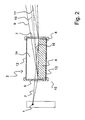
- Fig. 2 is the X-ray arrangement of Fig. 1 in a vertical cross section, ie from the side shown.
- the incident beam 2 emanating from the X-ray source 1 enters the enclosure 3 through the entrance window 6, strikes a mirror surface 16 of the X-ray mirror 4, is reflected there and leaves the enclosure 3 through the exit window as a failing beam 9, 10, 11 7th
- the beryllium disks of the entrance and exit windows 6, 7, housing reinforcements 8 and a cover plate 12 and a bottom plate 13 are shown.
- the X-ray mirror 4 rests on the bottom plate 13 and is fixed on this in a manner not shown, such as by a mechanical clamping device or by a bond.
- the enclosure 3 houses in its interior 14 exclusively a single X-ray mirror 4.
- the interior 14 contains moreover a defined atmosphere, preferably high-purity argon or helium at a gas pressure of about 1.3 * 10 5 Pa.
- the outer dimensions of the encapsulation 3 are based on the size of the enclosed X-ray mirror 4, ie the outer dimensions of the encapsulation 3 are only slightly larger (up to a factor of 2) than the outer dimensions of the X-ray mirror 4 above the mirror surface 16 a distance of a few millimeters (typically up to about 12 mm) to the cover plate 12 of the enclosure 3 remains.
- the outer dimensions of the encapsulation 3 are approximately 30 mm in length, 15 mm in width and 15 mm in each case; According to the invention, the outer dimensions of an encapsulated X-ray mirror are each a maximum of 100 mm.
- the encapsulation 3 is firmly connected to the X-ray mirror 4 and protects the mirror surface 16 during assembly of the encapsulated X-ray mirror according to the invention against accidental contact and thus contamination or damage.
- the encapsulation 3 is easy to carry and handle together with the actual X-ray mirror 4, in particular with one hand.
- the encapsulated X-ray mirror is a single component for X-ray optics.
- the incident beam of X-rays impinges very flatly on the mirror surface 16, namely in grazing incidence.
- the course of the radiation beam 2, (and also the beam 9, 10, 11) is almost parallel to the mirror surface 16.
- the angle of incidence (and the angle of reflection) in the figures is shown slightly enlarged.
- the planes of the beryllium disks of the windows 6, 7 run perpendicular to the plane of the mirror surface 16. This ensures that the X-radiation strikes approximately perpendicular to the windows 6, 7 and can irradiate them with only slight reflection losses.
- mirror surface 16 in the FIG. 2 just shown, this can also be profiled, in particular having a paraboloid profile.
- An encapsulated X-ray mirror 30 has a reflective mirror surface 31.
- An encapsulation 32 which covers a part of the mirror surface 31 like a hood, is fastened to this mirror surface 31. Only this overstretched part of the mirror surface 31 is used for reflection of X-radiation.
- the encapsulation 32 has an entrance window 33 and an exit window 34, each made of beryllium.
- An interior 35 The encapsulation 32 is bounded by the partial walls of the encapsulation 32, in particular a cover plate 36 and side walls 37, the windows 33, 34 and the X-ray mirror 30 itself.
- the mirror surface 31 thus forms a boundary of the interior 35 of the encapsulation 32, in the interior 35 a to be able to include a defined atmosphere.
- a small volume of a defined atmosphere is permanently enclosed in order to limit the access of chemical substances during the irradiation of the mirror surface with X-radiation. This limits mirror-surface-causing chemical reactions at the mirror surface and extends the life of the X-ray mirror encapsulated in this way.
Landscapes
- Engineering & Computer Science (AREA)
- Physics & Mathematics (AREA)
- Chemical & Material Sciences (AREA)
- Nanotechnology (AREA)
- Theoretical Computer Science (AREA)
- Crystallography & Structural Chemistry (AREA)
- Mathematical Physics (AREA)
- Spectroscopy & Molecular Physics (AREA)
- General Engineering & Computer Science (AREA)
- High Energy & Nuclear Physics (AREA)
- Exposure Of Semiconductors, Excluding Electron Or Ion Beam Exposure (AREA)
- Analysing Materials By The Use Of Radiation (AREA)
- X-Ray Techniques (AREA)
Claims (9)
- Miroir à rayons X (30), en particulier miroir multicouche, conçu pour réfléchir un rayonnement X (2) sous incidence rasante, comportant un moyen intégré, solidaire du miroir à rayons X (30) pour protéger la surface de miroir (31) contre des influences indésirables qui modifient la surface et affectent l'effet réfléchissant,
le moyen pour protéger la surface de miroir (31) comprenant une encapsulation (32) de la surface de miroir (31), l'encapsulation (32) présentant une fenêtre d'entrée et de sortie (33, 34) transparente aux rayons X, et l'encapsulation (32) étant étanche à l'air,
caractérisé en ce
que l'encapsulation (32) est fixée sur la surface de miroir (31) et recouvre une partie de la surface de miroir (31) à la manière d'une calotte. - Miroir à rayons X (30) selon la revendication 1, caractérisé en ce que la surface de fenêtre de la fenêtre d'entrée (33) et/ou de la fenêtre de sortie (34) est inclinée d'un angle de fenêtre de 90° ± 25°, en particulier 90° ± 5°, par rapport à la surface de miroir (31).
- Miroir à rayons X (30) selon une des revendications précédentes, caractérisé en ce que l'encapsulation étanche à l'air (32) est mise au vide ou que l'encapsulation étanche à l'air (32) contient une atmosphère définie, les matériaux d'encapsulation étant choisis en particulier de façon que l'atmosphère soit chimiquement inerte, de préférence dépourvue d'oxygène, en présence de l'encapsulation (32) même sous l'influence du rayonnement X.
- Miroir à rayons X (30) selon une des revendications précédentes, caractérisé en ce que les matériaux d'encapsulation sont choisis de façon qu'ils n'émettent pas de gaz, en particulier qu'ils ne cèdent pas de molécules oxydantes.
- Miroir à rayons X (30) selon une des revendications précédentes, caractérisé en ce que les coefficients de dilatation thermique des matériaux d'encapsulation et du miroir à rayons X (30) sont adaptés les uns aux autres.
- Miroir à rayons X (30) selon une des revendications précédentes, caractérisé en ce que le miroir à rayons X (30) et l'encapsulation (32) sont construits sans contraintes mécaniques.
- Miroir à rayons X (30) selon une des revendications précédentes, caractérisé en ce que le miroir à rayons X (30) est conçu pour un rayonnement X (2) sous incidence rasante avec un angle d'incidence < 5°, en particulier < 3°, par rapport à la surface de miroir (31).
- Procédé de fabrication d'un miroir à rayons X (30) selon une des revendications précédentes, caractérisé en ce que l'encapsulation (32) est assemblée avec le miroir à rayons X (30) dans des conditions de salle blanche.
- Procédé selon la revendication 8, caractérisé en ce que l'encapsulation (32) est assemblée avec le miroir à rayons X (30) sous atmosphère protectrice, l'atmosphère protectrice étant en particulier identique à une atmosphère présente dans l'encapsulation (32).
Applications Claiming Priority (2)
| Application Number | Priority Date | Filing Date | Title |
|---|---|---|---|
| DE10334169 | 2003-07-26 | ||
| DE2003134169 DE10334169A1 (de) | 2003-07-26 | 2003-07-26 | Gekapselter Röntgenspiegel |
Publications (3)
| Publication Number | Publication Date |
|---|---|
| EP1503386A2 EP1503386A2 (fr) | 2005-02-02 |
| EP1503386A3 EP1503386A3 (fr) | 2009-08-05 |
| EP1503386B1 true EP1503386B1 (fr) | 2011-12-28 |
Family
ID=33521419
Family Applications (1)
| Application Number | Title | Priority Date | Filing Date |
|---|---|---|---|
| EP04016846A Expired - Lifetime EP1503386B1 (fr) | 2003-07-26 | 2004-07-16 | Miroir encapsulé pour rayons-X |
Country Status (2)
| Country | Link |
|---|---|
| EP (1) | EP1503386B1 (fr) |
| DE (1) | DE10334169A1 (fr) |
Families Citing this family (3)
| Publication number | Priority date | Publication date | Assignee | Title |
|---|---|---|---|---|
| DE102010034597A1 (de) * | 2010-08-12 | 2012-02-16 | Ifg - Institute For Scientific Instruments Gmbh | Röntgenoptik mit Strahleneintrittsfenster und Strahlenaustrittsfenster |
| DE102012208710B3 (de) * | 2012-05-24 | 2013-09-19 | Incoatec Gmbh | Verfahren zur Herstellung einer einkristallinen Röntgenblende und Röntgenanalysegerät mit einkristalliner Röntgenblende |
| CN112638261B (zh) | 2018-09-04 | 2025-06-27 | 斯格瑞公司 | 利用滤波的x射线荧光的系统和方法 |
Family Cites Families (7)
| Publication number | Priority date | Publication date | Assignee | Title |
|---|---|---|---|---|
| JPH01198021A (ja) * | 1988-02-03 | 1989-08-09 | Nec Corp | X線露光装置 |
| DE4027285A1 (de) * | 1990-08-29 | 1992-03-05 | Zeiss Carl Fa | Roentgenmikroskop |
| US6108397A (en) * | 1997-11-24 | 2000-08-22 | Focused X-Rays, Llc | Collimator for x-ray proximity lithography |
| US6498685B1 (en) * | 1999-01-11 | 2002-12-24 | Kenneth C. Johnson | Maskless, microlens EUV lithography system |
| JP3741411B2 (ja) * | 1999-10-01 | 2006-02-01 | 株式会社リガク | X線集光装置及びx線装置 |
| EP1126477A3 (fr) * | 2000-02-14 | 2003-06-18 | Leica Microsystems Lithography GmbH | Procédé d'examen de structures dans un substrat sémiconducteur |
| DE10134267B4 (de) | 2001-07-18 | 2007-03-01 | Gkss-Forschungszentrum Geesthacht Gmbh | Einrichtung zur Reflexion von Röntgenstrahlen |
-
2003
- 2003-07-26 DE DE2003134169 patent/DE10334169A1/de not_active Ceased
-
2004
- 2004-07-16 EP EP04016846A patent/EP1503386B1/fr not_active Expired - Lifetime
Non-Patent Citations (1)
| Title |
|---|
| XENOCS: "Xenocs Products", 16 June 2003 (2003-06-16), Retrieved from the Internet <URL:http://web.archive.org/web/20030613112635/www.xenocs.com/products.php> [retrieved on 20100705] * |
Also Published As
| Publication number | Publication date |
|---|---|
| EP1503386A3 (fr) | 2009-08-05 |
| DE10334169A1 (de) | 2005-02-24 |
| EP1503386A2 (fr) | 2005-02-02 |
Similar Documents
| Publication | Publication Date | Title |
|---|---|---|
| EP1629268B1 (fr) | Procédé et dispositif pour nettoyer au moins un composant optique | |
| EP0646283B1 (fr) | Fenetre de sortie pour faisceau electronique | |
| DE69817035T2 (de) | Strahlungsdetektor und Verfahren zu seiner Herstellung | |
| DE19808795C2 (de) | Wärmestrahlen reflektierendes Schichtsystem für transparente Substrate | |
| DE4301146A1 (fr) | ||
| EP1772758B1 (fr) | Fibre optique à noyau creux | |
| DE2926461A1 (de) | Solarzellenmodul | |
| WO2019025162A1 (fr) | Agencement optique pour rayonnement ultraviolet extrême comportant un écran pour la protection contre l'effet caustique d'un plasma | |
| DE102016224200A1 (de) | Verfahren zum Reparieren von reflektiven optischen Elementen für die EUV-Lithographie | |
| EP1947444A2 (fr) | Dispositif destiné à la vérification de la lumière ou du vieillissement d'un boîtier d'échantillons à l'aide d'un filtre à rayons UV intégré | |
| EP3660550A2 (fr) | Matière composite réfléchissante dotée d'un support en aluminium et d'une couche de réflexion en argent | |
| DE69709508T2 (de) | Fluoreszenzlampe mit Dünnschichtphotokatalysator und Herstellungsverfahren derselben | |
| WO2021037508A1 (fr) | Élément optique pour réfléchir un rayonnement euv, système de lithographie euv et procédé d'obturation d'un interstice | |
| EP1503386A2 (fr) | Miroir encapsulé pour rayons-X | |
| EP2582640B1 (fr) | Matériau du revêtement ou réflecteur pour l' application à haute température | |
| EP4237884B1 (fr) | Élément optique, en particulier pour la réflexion d'un rayonnement ultraviolet extrême, ensemble optique et procédé de fabrication d'un élément optique | |
| DE2813919A1 (de) | Eingangs-bildschirm fuer roentgen- fluoreszenzvervielfacher | |
| EP2494577A1 (fr) | Dispositif pour réfléchir des électrons accélérés | |
| DE102018128243A1 (de) | Herstellvorrichtung zur additiven Fertigung dreidimensionaler Bauteile | |
| DE102008000957A1 (de) | Schutzmodul sowie EUV-Lithographievorrichtung mit Schutzmodul | |
| DE102017222690A1 (de) | Optisches Element mit einem Wasserstoff-Desorptionsmaterial | |
| DE19525735A1 (de) | Abstandhalter für Isolierverglasungen | |
| DE102021205985A1 (de) | Optische Anordnung für die EUV-Lithographie und Verfahren zum Regenerieren eines gasbindenden Bauteils | |
| DE2854213A1 (de) | Verfahren zur herstellung von zu isolierscheiben verarbeitbaren, infrarotreflektierenden fensterscheiben und durch das verfahren hergestellte fensterscheiben sowie isolierscheiben | |
| WO2017202579A1 (fr) | Élément optique et système de lithographique extrême ultraviolet |
Legal Events
| Date | Code | Title | Description |
|---|---|---|---|
| PUAI | Public reference made under article 153(3) epc to a published international application that has entered the european phase |
Free format text: ORIGINAL CODE: 0009012 |
|
| AK | Designated contracting states |
Kind code of ref document: A2 Designated state(s): AT BE BG CH CY CZ DE DK EE ES FI FR GB GR HU IE IT LI LU MC NL PL PT RO SE SI SK TR |
|
| AX | Request for extension of the european patent |
Extension state: AL HR LT LV MK |
|
| PUAL | Search report despatched |
Free format text: ORIGINAL CODE: 0009013 |
|
| AK | Designated contracting states |
Kind code of ref document: A3 Designated state(s): AT BE BG CH CY CZ DE DK EE ES FI FR GB GR HU IE IT LI LU MC NL PL PT RO SE SI SK TR |
|
| AX | Request for extension of the european patent |
Extension state: AL HR LT LV MK |
|
| 17P | Request for examination filed |
Effective date: 20091113 |
|
| AKX | Designation fees paid |
Designated state(s): DE FR NL |
|
| 17Q | First examination report despatched |
Effective date: 20100709 |
|
| GRAP | Despatch of communication of intention to grant a patent |
Free format text: ORIGINAL CODE: EPIDOSNIGR1 |
|
| GRAS | Grant fee paid |
Free format text: ORIGINAL CODE: EPIDOSNIGR3 |
|
| GRAA | (expected) grant |
Free format text: ORIGINAL CODE: 0009210 |
|
| AK | Designated contracting states |
Kind code of ref document: B1 Designated state(s): DE FR NL |
|
| REG | Reference to a national code |
Ref country code: DE Ref legal event code: R096 Ref document number: 502004013181 Country of ref document: DE Effective date: 20120308 |
|
| REG | Reference to a national code |
Ref country code: NL Ref legal event code: T3 |
|
| PLBE | No opposition filed within time limit |
Free format text: ORIGINAL CODE: 0009261 |
|
| STAA | Information on the status of an ep patent application or granted ep patent |
Free format text: STATUS: NO OPPOSITION FILED WITHIN TIME LIMIT |
|
| 26N | No opposition filed |
Effective date: 20121001 |
|
| REG | Reference to a national code |
Ref country code: DE Ref legal event code: R097 Ref document number: 502004013181 Country of ref document: DE Effective date: 20121001 |
|
| REG | Reference to a national code |
Ref country code: FR Ref legal event code: PLFP Year of fee payment: 13 |
|
| REG | Reference to a national code |
Ref country code: FR Ref legal event code: PLFP Year of fee payment: 14 |
|
| REG | Reference to a national code |
Ref country code: FR Ref legal event code: PLFP Year of fee payment: 15 |
|
| PGFP | Annual fee paid to national office [announced via postgrant information from national office to epo] |
Ref country code: NL Payment date: 20230720 Year of fee payment: 20 |
|
| PGFP | Annual fee paid to national office [announced via postgrant information from national office to epo] |
Ref country code: FR Payment date: 20230724 Year of fee payment: 20 Ref country code: DE Payment date: 20230720 Year of fee payment: 20 |
|
| P01 | Opt-out of the competence of the unified patent court (upc) registered |
Effective date: 20231116 |
|
| REG | Reference to a national code |
Ref country code: NL Ref legal event code: MK Effective date: 20240715 |