EP1504960B1 - Appareil et méthode pour améliorer la vision dans un vehicule - Google Patents
Appareil et méthode pour améliorer la vision dans un vehicule Download PDFInfo
- Publication number
- EP1504960B1 EP1504960B1 EP04017287.6A EP04017287A EP1504960B1 EP 1504960 B1 EP1504960 B1 EP 1504960B1 EP 04017287 A EP04017287 A EP 04017287A EP 1504960 B1 EP1504960 B1 EP 1504960B1
- Authority
- EP
- European Patent Office
- Prior art keywords
- image
- camera
- motor vehicle
- excerpt
- data
- Prior art date
- Legal status (The legal status is an assumption and is not a legal conclusion. Google has not performed a legal analysis and makes no representation as to the accuracy of the status listed.)
- Expired - Lifetime
Links
- 238000000034 method Methods 0.000 title claims description 32
- 238000012545 processing Methods 0.000 claims description 19
- 230000003287 optical effect Effects 0.000 claims description 10
- 238000004891 communication Methods 0.000 claims description 5
- 230000006870 function Effects 0.000 description 48
- 238000001514 detection method Methods 0.000 description 17
- 238000004364 calculation method Methods 0.000 description 11
- 238000010586 diagram Methods 0.000 description 8
- 238000012937 correction Methods 0.000 description 4
- 230000006978 adaptation Effects 0.000 description 3
- 230000007423 decrease Effects 0.000 description 3
- 238000013461 design Methods 0.000 description 3
- 230000001133 acceleration Effects 0.000 description 2
- 230000001419 dependent effect Effects 0.000 description 2
- 238000013213 extrapolation Methods 0.000 description 2
- 230000004297 night vision Effects 0.000 description 2
- 241001465754 Metazoa Species 0.000 description 1
- 230000003044 adaptive effect Effects 0.000 description 1
- 238000013528 artificial neural network Methods 0.000 description 1
- 230000006835 compression Effects 0.000 description 1
- 238000007906 compression Methods 0.000 description 1
- 238000001816 cooling Methods 0.000 description 1
- 230000008878 coupling Effects 0.000 description 1
- 238000010168 coupling process Methods 0.000 description 1
- 238000005859 coupling reaction Methods 0.000 description 1
- 238000006073 displacement reaction Methods 0.000 description 1
- 238000000605 extraction Methods 0.000 description 1
- 238000005286 illumination Methods 0.000 description 1
- 238000003384 imaging method Methods 0.000 description 1
- 238000009434 installation Methods 0.000 description 1
- 239000011159 matrix material Substances 0.000 description 1
- 238000012544 monitoring process Methods 0.000 description 1
- 238000010606 normalization Methods 0.000 description 1
- PHEDXBVPIONUQT-RGYGYFBISA-N phorbol 13-acetate 12-myristate Chemical compound C([C@]1(O)C(=O)C(C)=C[C@H]1[C@@]1(O)[C@H](C)[C@H]2OC(=O)CCCCCCCCCCCCC)C(CO)=C[C@H]1[C@H]1[C@]2(OC(C)=O)C1(C)C PHEDXBVPIONUQT-RGYGYFBISA-N 0.000 description 1
- 239000000700 radioactive tracer Substances 0.000 description 1
- 230000001105 regulatory effect Effects 0.000 description 1
Images


Classifications
-
- B—PERFORMING OPERATIONS; TRANSPORTING
- B60—VEHICLES IN GENERAL
- B60R—VEHICLES, VEHICLE FITTINGS, OR VEHICLE PARTS, NOT OTHERWISE PROVIDED FOR
- B60R1/00—Optical viewing arrangements; Real-time viewing arrangements for drivers or passengers using optical image capturing systems, e.g. cameras or video systems specially adapted for use in or on vehicles
- B60R1/20—Real-time viewing arrangements for drivers or passengers using optical image capturing systems, e.g. cameras or video systems specially adapted for use in or on vehicles
- B60R1/30—Real-time viewing arrangements for drivers or passengers using optical image capturing systems, e.g. cameras or video systems specially adapted for use in or on vehicles providing vision in the non-visible spectrum, e.g. night or infrared vision
-
- H—ELECTRICITY
- H04—ELECTRIC COMMUNICATION TECHNIQUE
- H04N—PICTORIAL COMMUNICATION, e.g. TELEVISION
- H04N7/00—Television systems
- H04N7/18—Closed-circuit television [CCTV] systems, i.e. systems in which the video signal is not broadcast
- H04N7/183—Closed-circuit television [CCTV] systems, i.e. systems in which the video signal is not broadcast for receiving images from a single remote source
-
- B—PERFORMING OPERATIONS; TRANSPORTING
- B60—VEHICLES IN GENERAL
- B60R—VEHICLES, VEHICLE FITTINGS, OR VEHICLE PARTS, NOT OTHERWISE PROVIDED FOR
- B60R1/00—Optical viewing arrangements; Real-time viewing arrangements for drivers or passengers using optical image capturing systems, e.g. cameras or video systems specially adapted for use in or on vehicles
- B60R1/20—Real-time viewing arrangements for drivers or passengers using optical image capturing systems, e.g. cameras or video systems specially adapted for use in or on vehicles
- B60R1/22—Real-time viewing arrangements for drivers or passengers using optical image capturing systems, e.g. cameras or video systems specially adapted for use in or on vehicles for viewing an area outside the vehicle, e.g. the exterior of the vehicle
- B60R1/23—Real-time viewing arrangements for drivers or passengers using optical image capturing systems, e.g. cameras or video systems specially adapted for use in or on vehicles for viewing an area outside the vehicle, e.g. the exterior of the vehicle with a predetermined field of view
- B60R1/24—Real-time viewing arrangements for drivers or passengers using optical image capturing systems, e.g. cameras or video systems specially adapted for use in or on vehicles for viewing an area outside the vehicle, e.g. the exterior of the vehicle with a predetermined field of view in front of the vehicle
-
- H—ELECTRICITY
- H04—ELECTRIC COMMUNICATION TECHNIQUE
- H04N—PICTORIAL COMMUNICATION, e.g. TELEVISION
- H04N25/00—Circuitry of solid-state image sensors [SSIS]; Control thereof
- H04N25/40—Extracting pixel data from image sensors by controlling scanning circuits, e.g. by modifying the number of pixels sampled or to be sampled
- H04N25/46—Extracting pixel data from image sensors by controlling scanning circuits, e.g. by modifying the number of pixels sampled or to be sampled by combining or binning pixels
-
- B—PERFORMING OPERATIONS; TRANSPORTING
- B60—VEHICLES IN GENERAL
- B60R—VEHICLES, VEHICLE FITTINGS, OR VEHICLE PARTS, NOT OTHERWISE PROVIDED FOR
- B60R2300/00—Details of viewing arrangements using cameras and displays, specially adapted for use in a vehicle
- B60R2300/10—Details of viewing arrangements using cameras and displays, specially adapted for use in a vehicle characterised by the type of camera system used
- B60R2300/107—Details of viewing arrangements using cameras and displays, specially adapted for use in a vehicle characterised by the type of camera system used using stereoscopic cameras
-
- B—PERFORMING OPERATIONS; TRANSPORTING
- B60—VEHICLES IN GENERAL
- B60R—VEHICLES, VEHICLE FITTINGS, OR VEHICLE PARTS, NOT OTHERWISE PROVIDED FOR
- B60R2300/00—Details of viewing arrangements using cameras and displays, specially adapted for use in a vehicle
- B60R2300/20—Details of viewing arrangements using cameras and displays, specially adapted for use in a vehicle characterised by the type of display used
- B60R2300/205—Details of viewing arrangements using cameras and displays, specially adapted for use in a vehicle characterised by the type of display used using a head-up display
-
- B—PERFORMING OPERATIONS; TRANSPORTING
- B60—VEHICLES IN GENERAL
- B60R—VEHICLES, VEHICLE FITTINGS, OR VEHICLE PARTS, NOT OTHERWISE PROVIDED FOR
- B60R2300/00—Details of viewing arrangements using cameras and displays, specially adapted for use in a vehicle
- B60R2300/30—Details of viewing arrangements using cameras and displays, specially adapted for use in a vehicle characterised by the type of image processing
- B60R2300/302—Details of viewing arrangements using cameras and displays, specially adapted for use in a vehicle characterised by the type of image processing combining image information with GPS information or vehicle data, e.g. vehicle speed, gyro, steering angle data
-
- B—PERFORMING OPERATIONS; TRANSPORTING
- B60—VEHICLES IN GENERAL
- B60R—VEHICLES, VEHICLE FITTINGS, OR VEHICLE PARTS, NOT OTHERWISE PROVIDED FOR
- B60R2300/00—Details of viewing arrangements using cameras and displays, specially adapted for use in a vehicle
- B60R2300/70—Details of viewing arrangements using cameras and displays, specially adapted for use in a vehicle characterised by an event-triggered choice to display a specific image among a selection of captured images
-
- B—PERFORMING OPERATIONS; TRANSPORTING
- B60—VEHICLES IN GENERAL
- B60R—VEHICLES, VEHICLE FITTINGS, OR VEHICLE PARTS, NOT OTHERWISE PROVIDED FOR
- B60R2300/00—Details of viewing arrangements using cameras and displays, specially adapted for use in a vehicle
- B60R2300/80—Details of viewing arrangements using cameras and displays, specially adapted for use in a vehicle characterised by the intended use of the viewing arrangement
- B60R2300/8006—Details of viewing arrangements using cameras and displays, specially adapted for use in a vehicle characterised by the intended use of the viewing arrangement for monitoring and displaying scenes of vehicle interior, e.g. for monitoring passengers or cargo
-
- B—PERFORMING OPERATIONS; TRANSPORTING
- B60—VEHICLES IN GENERAL
- B60R—VEHICLES, VEHICLE FITTINGS, OR VEHICLE PARTS, NOT OTHERWISE PROVIDED FOR
- B60R2300/00—Details of viewing arrangements using cameras and displays, specially adapted for use in a vehicle
- B60R2300/80—Details of viewing arrangements using cameras and displays, specially adapted for use in a vehicle characterised by the intended use of the viewing arrangement
- B60R2300/804—Details of viewing arrangements using cameras and displays, specially adapted for use in a vehicle characterised by the intended use of the viewing arrangement for lane monitoring
Definitions
- the invention relates to a method and a device for improving the visibility in a motor vehicle.
- a camera device for motor vehicles having a variably orientable camera for detecting a road ahead of a vehicle is known. It is proposed to carry out the tracking of the camera in yaw and pitch angle direction by a mechanical device in the form of a movable platform by drive. The tracking of the camera takes place before entering the curve due to information from a navigation system. References to a method and a device for improving the visibility in a motor vehicle, which allow a compact design of the camera, are missing in the DE 199 50 033 A1 ,
- the WO 02/36389 A1 discloses a night vision device for a motor vehicle in which a camera is provided which detects an infrared image on the road in front of the motor vehicle, wherein a video signal generated by the camera is processed by a signal processor.
- a signal processor In this case, the field of view of the image displayed on a monitor is selected in accordance with a control signal. In particular, the width of the field of view can be reduced with increasing speed.
- the method described below with the features of claim 1 has the particular advantage that it is inexpensive to implement, since only computing power is needed in the processing unit, compared to a complex and expensive hardware and software solution with a mechanical drive of the camera for tracking of the detection area, and the image section is provided by reading out only pixel areas of the CMOS image sensor of the camera.
- the course of the road especially in strong bends, fully detectable.
- the proportion of usable image information increases in an advantageous manner. It is advantageous that the visibility of the system is approximately constant and independent of the pitch angle of the motor vehicle.
- the pitch angle of the motor vehicle changes, for example during compression during braking and / or when starting the motor vehicle during acceleration.
- the method contributes to an increase in traffic safety, since the road is clearly visible even when driving to the images of the camera by the driver.
- a driver can Motor vehicle by turning the head change the field of view.
- the method described below provides an analogue viewing area, in particular at night.
- non-illustrative camera systems for example devices for lane departure warning
- relevant areas of the scene are detected in an advantageous manner.
- detection reliability is high while precious computing power is concentrated on relevant areas.
- the method described below has the advantage that the system has a long service life and low wear, since no moving parts are required for tracking.
- a compact design of the system allows, for example, no additional space for drives and / or cooling power for power loss of drives is necessary.
- a two-axis tracking, ie in the yaw and pitch angle direction compared to a uniaxial tracking, for example in the yaw angle direction substantially the same effort is necessary.
- the method is possible on a three-axis tracking in yaw, pitch and roll angle direction. It is also advantageous if the size of the image detail and / or the position of the image detail is additionally or alternatively set as a function of the current direction of travel of the motor vehicle and / or the direction of travel of the motor vehicle desired by the driver.
- the current direction of travel can be determined, for example, from the image data of the at least one camera, while the driving direction desired by the driver can be determined, for example, from the steering wheel position via a steering wheel sensor and / or via the steering angle via at least one steering angle sensor.
- Particularly advantageous is the determination of the course of the road as a function of image data of one and / or the at least one camera, since in this case the vehicle position with respect to the road can be determined exactly and at the same time the course of the road is currently ascertainable.
- This has the advantage that the change of the position of the image section within the at least one image is made possible even before the motor vehicle enters the curve.
- a forward-looking tracking of the detection range of the camera is made possible in a particularly advantageous manner.
- the setting of the size of the image detail and / or the position of the image detail within the at least one image at least in dependence on the data of at least one further motor vehicle sensor, in particular at least one Steering wheel sensor and / or at least one steering angle sensor, advantageously contributes to a robust method. It is particularly advantageous if the size of the image detail and / or the position of the image detail within the at least one image is set as a function of the driver's line of sight. The look and thus the line of sight of the driver is generally directed to relevant scenes. By an interior camera, for example, receives the face of the driver, the viewing direction is determined, for example, by evaluating the position of the eyes.
- the method described below in which the size of the image section and / or the position of the image section within the at least one image is set at least in dependence on the setting of the headlights.
- the advantage here is that the captured scene in the image section with the illumination by the headlights is approximately equal.
- the size of the image section is adjusted in dependence on the position of the image section such that the opening angle of the image section is approximately constant.
- the user thereby obtains a comparable coverage area, as he is accustomed to when the head is turned.
- An adaptation of the at least one image section to the pixel resolution of the display unit is advantageous since in this case the entire image section is displayed independently of its size.
- the image section is post-processed, wherein the natural vignetting, ie the drop in intensity towards the edge of the image, of the image is compensated.
- the natural vignetting ie the drop in intensity towards the edge of the image
- the viewing angle of the camera ie in yaw and / or pitch and / or roll angle direction, is tracked purely electronically. This is done by tracking the image section, the so-called window of interest, on the image sensor of a CMOS camera.
- the optical axis of the camera is not changed, but the camera remains constantly aligned.
- the direction of the optical axis is determined by two points, the main objective point and the center of the image sensor.
- the read-out of the pixel area of the image sensor of the CMOS camera (window of interest) is read by writing configuration registers directly in the CMOS image sensor.
- the window of interest of today's CMOS image sensors can only be selected at right angles, but will allow more degrees of freedom in future sensor generations. For diagonal-shaped image sections, a direct roll angle correction is then also possible. With today's CMOS image sensors, simple tracking in the yaw angle direction and / or in the pitch angle direction is already possible. A superposition of tracking in yaw and / or pitch and / or roll angle direction is easily possible. This leads to the extent that in extreme cases the image window of interest lies exactly in the corner of the image sensor pixel area.
- the adjustment of the size of the image detail and / or the position of the image section takes place at least as a function of the course of the road, the information about the course of the road being obtained directly from the image data of the camera, in particular by utilizing the information of the Lane Departure Warning function.
- the course of the road in the pitch angle direction can be determined in a particularly advantageous manner with a stereo camera.
- the information about the course of the road is obtained by evaluating further sources of information, such as data from a navigation system.
- the function module for calculating the size of the image section (window of interest) guarantees a constant opening angle, as is the case with the mechanically rotated camera.
- the function module for imaging the variably large image detail (window of interest) on the target image size allows simple further processing and / or a simple representation on a display unit (display).
- the function module for compensation of the intensity drop to the edge of the frame guarantees constant image brightness.
- the pitch angle means the deviation of the driving axis of the motor vehicle in the vertical direction, while the yaw angle describes the deviation of the driving axis of the motor vehicle in the horizontal direction.
- the roll angle is a measure of the rotation of the motor vehicle about the driving axle.
- the steering wheel position detectable by at least one steering wheel sensor
- the steering angle of the steering wheels detectable by at least one steering angle sensor
- the angle of the headlights in the horizontal and vertical directions Data from a vehicle dynamics control system (ESP), the yaw angle of the motor vehicle detectable by at least one yaw rate sensor, data of a navigation system over the course of the road, data of a camera-based lane detection system over the course of the road, data of an external guidance system over the course of the road, for example guide wire, radio, satellite
- Data from further sensors which calculate the yaw angle or from which the current yaw angle can be calculated and / or image data of a camera-based interior video sensor system, which is a calculation of Magnoliaric driver's attention.
- data of the chassis in particular of the active chassis
- data of the dynamic Lichtweitenkorrektur image data of at least one camera and / or image data of a camera-based interior video sensors, which allows a calculation of the driver's line of sight.
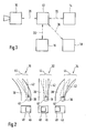
- FIG. 12 shows a block diagram of the preferred embodiment, consisting of a CMOS camera 10 and a processing unit 12, which are connected by a signal line 20.
- the processing unit 12 is connected via a signal line 20 to at least one information system 16 of the motor vehicle.
- the processing unit 12 is connected via further signal lines 20 to a display unit 14 and a subsequent system 18.
- the CMOS camera 10 is attached to the windshield of the motor vehicle.
- the CMOS camera 10 is mounted in the interior of the motor vehicle in the region of the interior rear view mirror, wherein the optical axis of the camera 10 for detecting the traffic space is oriented such that the detection area of the CMOS camera 10 covers at least parts of the area in front of the motor vehicle in the direction of travel.
- the processing unit 12 consists of several, in FIG. 5
- the function modules 70, 72, 74, 76, 78 are programs or program steps of at least one microprocessor in the processing unit 12 and / or by means of programmable logic, in particular ASIC and / or FPGA, realized.
- the display unit 14 is a display and / or a head-up display.
- the following system 18 serves to realize at least one further camera function, for example the lane departure warning.
- the data is transmitted via the signal lines 20 electrically and / or optically and / or by radio, wherein the signal lines 20 is a 1-wire line and / or a 2-wire line and / or a multi-wire line.
- the signal lines are designed alternatively or additionally as a bus line.
- FIG. 2 3 shows scenes for explaining the position of the image detail 48 within the image 46 in the yaw angle direction.
- the first scene 30 shows a motor vehicle 36 on a road 38 with lane markings 40.
- the motor vehicle 36 travels on the lane 42 in the direction of travel, with the road 38 and thus the lane 42 making a left turn.
- the detection area 44 of the camera is shifted to the inside of the curve.
- the second scene 32 shows a motor vehicle 36 on a road 38 with lane markings 40, the motor vehicle being on the lane 42 and driving straight ahead.
- the detection area 44 of the camera is oriented in the direction of travel for detecting the scene of the lane 42 and the road 38.
- the image section 48 is located in the middle of the image 46 FIG. 2 a third scene 34 is shown in which the motor vehicle 36 is also on the road 38 with lane markings 40, the road 38 and the lane 42 making a right turn.
- the detection area 44 of the camera is aligned such that relevant areas of the lane 42 and the road 38 of this right turn are detected.
- the image section 48 is shifted in the image 46 in the horizontal direction to the left. Fundamental to this is that image sensors are available for cameras with large pixel matrices, for example 2272 x 1704 pixels.
- the size of the image sensor exceeds the size of automotive display units (displays and / or head-up displays), for example, have a resolution of 640 x 480 pixels.
- image sections in the size of about 640 x 480 pixels are sufficient.
- a CMOS image sensor having a size of the pixel matrix and thus the image 46 of 2272 x 1704 pixels is used.
- frame 48 has a size of 640 x 480 pixels.
- FIG. 3 shows three scenes for explaining the position of the image section 48 in the image 46 in the pitch angle direction.
- a motor vehicle 36 is shown in accelerated straight-ahead driving. Due to the acceleration of the front portion of the motor vehicle 36 is raised. To compensate for this pitching movement and to align the detection area 44 of the camera with the relevant areas, the image detail 48 in the image 46 is shifted upward so that the camera looks downwards.
- a motor vehicle 36 is also shown, wherein the motor vehicle 36 is unaccelerated.
- the image section 48 is located substantially in the center of the image 46 so that the detection area 44 of the camera also detects the relevant areas of the street.
- a further third scene 54 is shown, in which the motor vehicle 36 is braked.
- the front part of the motor vehicle lowers, while the rear part is raised.
- the image section 48 is located at the bottom of the image 46, so that the Detection range 44 of the camera is aligned to the relevant areas of the road.
- FIG. 4 shows three scenes for explaining the setting of the size of the image section 48 in the image 46. If a picture section 48 (window of interest) of the same size is slid over the image area (image 46) of the image sensor (image), the opening angle changes due to the geometric conditions of the image field. This becomes smaller, the further one moves away from the optical axis of the camera. If you want to achieve the same opening angle over the entire work area, so the entire image 46, then the image section 48 must be adjusted in size. In FIG. 4 this is exemplified in yaw angle direction. In the preferred embodiment, this compensation of the size of the image section 48 is performed in yaw and / or pitch angle direction, wherein the calculation in the pitch angle direction is performed analogously.
- the image detail 48 in the image 46 is located substantially in the center of the image both in the horizontal and in the vertical direction.
- the position of the image section 48 is shifted to the right within the image 46, for example due to a left turn of the motor vehicle and / or a road course in which the road makes a left turn.
- the width 58 of the image detail 48 in the first scene 30 is increased by the amount ⁇ x.
- An analogous situation results in the third scene 34, in which the image section 48 is shifted in the image 46 to the left and thereby the width 58 of the image section 48 has been increased by the amount .DELTA.x.
- the adjustment of the size of the image section 48 as a function of the position of the image section 48 within the at least one image 46 is such that the opening angle of the image section 48 is approximately constant by changing the width 58 and / or the height 56 of the image section 48 in FIG
- Dependence of the image sensor size and / or the focal length of the lens and / or the opening angle of the image detail and / or the deviation from the viewing direction is determined.
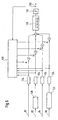
- FIG. 5 shows a block diagram of the signal flow of the preferred embodiment, consisting of the in FIG. 1 explained components, the camera 10 and a processing unit 12, and a display unit 14 for performing camera functions, information systems 16 of the motor vehicle and subsequent systems 18 for non-representative camera functions.
- the processing unit 12 consists of 5 function modules 70, 72, 74, 76, 78.
- the first function module 70 the currently required pitch angle 106 of the camera 10 is calculated.
- data of the camera 10 and / or of information systems 16 of the motor vehicle are alternatively or jointly used.
- the input variables used are, for example, data 80 of the chassis, in particular of the active chassis, of the motor vehicle and / or image data 82 of the camera 10 and / or data 84 of the dynamic light range correction and / or image data 86 of an interior camera, for example for determining the driver's line of sight.
- the first function module 70 calculates from the input data the pitch angle 106, which is transmitted to the third function module 74.
- the currently required yaw angle 108 of the camera 10 is calculated from various input variables of the camera 10 and / or from other information systems 16 of the motor vehicle and transmitted to the third function module 74.
- ESP driving dynamics control
- a yaw rate sensor and / or data 102 of a device for motor vehicle environment communication or motor vehicle motor vehicle communication and / or image data 104 of an interior camera used.
- the third module 74 calculates the size of the image detail and / or the position of the image detail within the at least one image from the pitch angle 106 and the yaw angle 108, with setting parameters 110 of the camera being transmitted from the third function module 74 to the camera 10.
- the corresponding image detail in the form of image data 112 is read from the CMOS camera 10 and transmitted to the fourth function module 76.
- the image detail is displayed on the target image size of the display unit 14 and / or the required size for the subsequent systems 18.
- the target image size should be constant because the resolution of the display unit 14 is fixed.
- the fourth function module 76 brings the image size to a uniform size by variable subsampling and / or zooming.
- the distortion is compensated by the lens. This is done, for example, via bilinear interpolation using look-up tables. Distortion is due in particular to non-optimal placement, for example, for constructive reasons, the aperture in the lens.
- the adjusted image data 114 are transmitted from the fourth function module 76 to the fifth function module 78. Due to the geometric conditions in the camera 10, the intensity decreases as one moves away from the optical axis. This is called natural vignetting (edge shading). This decrease is not dependent on the image scene and can therefore be computationally compensated.
- this is done by look-up tables and / or maps.
- This functionality is provided by the fifth function module 78, which performs the compensation for this drop in intensity.
- the homogenous image data 116 is finally transmitted to the display unit 14 and / or subsequent systems 18 for providing camera functions such as lane departure warning.
- FIG. 6 12 shows a block diagram of the signal flow for calculating the pitch angle 106 of the camera in the function module 70 FIG. 5 of the preferred embodiment, consisting of function modules 120, 122, 124, 126, 128, 130. From the image data 80 of the front camera 10 and the image data 86 of the interior camera are in the function module 120 for pitch angle calculation and in the function module 122 to the driver angle calculation first estimates for the pitch angle or the line of sight of the driver in the pitch angle direction determined.
- all four input values for the pitch angle are temporally filtered in the function modules 124 and over weighting factors A1, A2, A3 , A4 weighted summed.
- the weighting factors A1, A2, A3, A4 are thereby changed by a classifier for the driving situation as a function module 126, which takes into account not only the last estimate for the pitch angle, but also the function module 130 for delaying z high minus 1-element, the current input values.
- fuzzy classifiers or neural networks are used.
- the required pitch angle 106 of the camera is calculated.
- at least one weighting factor A1, A2, A3, A4 is set to 0.
- the pitch angle 106 is calculated only from the data 80 of the chassis sensors and / or the pitch angle 106 is taken from the data 84 of the dynamic light correction.
- FIG. 7 12 shows a block diagram of the signal flow for calculating the yaw angle 108 of the camera in the function module 72 FIG. 5 of the preferred embodiment, consisting of functional modules 132, 134, 136, 138, 140, 142, 144.
- ESP vehicle dynamics control
- the information of the other sensors are processed in the further functional modules 134, 136, 138, ie the angle 92 of the headlights in the function module 134 for tracer extrapolation and / or the data 96 of the navigation system and / or the image data 98 of the camera in the function module 136 for tracing calculation and or the data 100 of further vehicle sensors in the function module 136 for the track calculation and / or the data 102 of a device for motor vehicle surroundings communication in the function module 136 for the track calculation and / or the image data 104 of an interior camera in the function module 138 for the field of view calculation, so that the relevant Points (points of interest) depending on these data sources are also present.
- the points of interest weighted in this way are then superimposed two-dimensionally in the function module 142, ie a 2-D overlay of the relevant points is made (2D overlay of the points of interest). This is done by entering and summing the weighted points of interest in a rasterized two-dimensional map (2D map).
- the desired yaw angle 108 is then determined by an adaptation method (fitting method), for example a least-squares method, by comparison (matching) with stored progressions of the relevant points 146 (point-of-interest progressions) determined by the camera.
- the calculated yaw angle 108 is preferably also used for the calculation of the next driving situation in the function module 140, the classifier for driving situations.
- At least one weighting factor B88, B90, B92, B94, B96, B98, B100, B102, B104 is set to 0, or at least one input variable 88, 90, 92, 94, 96, 98, 100, 102, 104 is not involved in the procedure because it is not present for a time or because of the vehicle.
- the yaw angle 108 is calculated only from the data 88 of the steering angle sensor and / or the yaw angle 108 is determined from the angle 92 of the headlights.
- the method, the device and the processing unit are used in two cameras, in particular a stereo camera. Furthermore, further installation locations of the at least one camera in the motor vehicle are conceivable.
- the method, the device and the processing unit can be used in a reversing camera, wherein the reversing camera is preferably attached to the rear window of the motor vehicle.
- the adaptation of the size of the image section is dispensed with.
- the opening angle of the image section changes when the position of the image section changes, no calculation effort is required to control the size of the image section.
- the image of the image section on the target image field size is omitted, since the image section has a constant size.
- the electronic tracking of the camera in yaw angle and / or pitch angle and / or roll angle direction is complemented by a mechanical tracking of the optical axis of the camera.
- the mechanical tracking of the optical axis of the camera for example, by electromechanical, pneumatic, hydraulic, piezo-mechanical and / or shape memory-based actuators.
- the entire camera is tracked in yaw angle and / or pitch angle and / or roll angle direction.
- a direct mechanical coupling of the camera is made to the steering.
- actuators are used, which track a mirror and / or other optical units, which are located in the beam path of the camera. This has the advantage that small masses are to be moved for tracking.
- the camera is rigidly mounted on the motor vehicle.
- the camera is housed in the tracking headlight in a further variant.
- the electronic and the mechanical tracking of the camera is combined in such a way that in each of the pitch angle and / or yaw angle and / or roll angle direction the electronic and / or the mechanical tracking is used.
- the use of the described method, the device and the processing unit is revealed in CMOS cameras, in that by observing (monitoring) the register settings of the CMOS image sensor, the tracking of the image area (area of interest or window-of-interest) is detected becomes.
- the use of the track information of the camera can be recognized by it, if the detection area is properly tracked before entering the curve, especially if navigation information is wrong and / or not available.
Landscapes
- Engineering & Computer Science (AREA)
- Multimedia (AREA)
- Mechanical Engineering (AREA)
- Signal Processing (AREA)
- Traffic Control Systems (AREA)
- Closed-Circuit Television Systems (AREA)
- Electric Propulsion And Braking For Vehicles (AREA)
Claims (9)
- Procédé d'amélioration de la vision dans un véhicule automobile, dans lequel
une caméra (10) du véhicule automobile, qui présente un capteur d'image CMOS, enregistre au moins une image de l'environnement du véhicule automobile,
au moins une partie (48) de la ou des images est délivrée,
la grandeur de la partie de l'image et/ou la position de la partie de l'image à l'intérieur de la ou des images sont ajustées par exemple au moins en fonction de l'évolution de la chaussée et/ou de la direction de déplacement du véhicule automobile en cours et/ou souhaitée par le conducteur et
la partie de l'image est transférée à une unité d'affichage (14) pour être affichée et/ou à des systèmes (48) situés en aval,
caractérisé en ce que
la caméra est commandée de telle sorte que la caméra délivre directement la partie de la ou des images et
en ce que la partie d'image est délivrée par lecture de zones de pixels du capteur d'image CMOS de la caméra en décrivant des registres de configuration du capteur d'image CMOS. - Procédé selon la revendication 1, caractérisé en ce que la largeur (58) de la partie d'image et/ou la hauteur (56) de la partie d'image sont ajustées en tant que taille de la partie d'image.
- Procédé selon l'une des revendications précédentes, caractérisé en ce que l'évolution de la chaussée est déterminée en fonction de données (96) d'au moins un système de navigation, de données d'image d'au moins une caméra (10), de données d'image de la ou des caméras, de données (102) d'au moins un dispositif de communication entre véhicules automobiles, de données d'au moins un dispositif de communication du véhicule automobile avec son environnement et/ou de données d'au moins un autre capteur (88, 90, 92, 94, 96, 98, 100, 102, 104) du véhicule automobile.
- Procédé selon l'une des revendications précédentes, caractérisé en ce que la taille de la partie d'image et/ou la position de la partie d'image dans la ou les images sont ajustées au moins en fonction des données d'au moins un autre capteur (88, 90, 92, 94, 96, 98, 100, 102, 104) du véhicule automobile.
- Procédé selon l'une des revendications précédentes, caractérisé en ce que la taille de la partie d'image et/ou la position de la partie d'image dans la ou les images sont ajustées au moins en fonction du réglage des phares du véhicule automobile.
- Procédé selon l'une des revendications précédentes, caractérisé en ce que la taille de la partie d'image est ajustée en fonction de la position de la partie d'image à l'intérieur de la ou des images.
- Procédé selon l'une des revendications précédentes, caractérisé en ce que la direction des l'axe optique de la caméra par rapport au véhicule automobile peut être ajustée par un entraînement mécanique.
- Procédé selon l'une des revendications précédentes, caractérisé en ce que la ou les parties d'image sont adaptées à la résolution de l'unité d'affichage (14).
- Dispositif d'amélioration de la vision dans un véhicule automobile, en particulier en vue de la mise en oeuvre du procédé selon au moins l'une des revendications 1 à 8, et présentant
au moins une caméra (10) du véhicule automobile dotée d'un capteur d'image CMOS et qui enregistre au moins une image de l'environnement du véhicule automobile et
au moins une unité de traitement (12),
la ou les unités de traitement délivrant au moins une partie (48) de la ou des images,
la ou les unités de traitement ajustant la taille de la partie d'image et/ou la position de la partie d'image à l'intérieur de la ou des images par exemple au moins en fonction de l'évolution de la chaussée et/ou de la direction de déplacement du véhicule automobile en cours et/ou souhaitée par le conducteur,
l'unité de traitement transférant la partie d'image à une unité d'affichage (14) pour l'afficher et/ou à des systèmes (18) situés en aval,
caractérisé en ce que
l'unité de traitement commande la caméra de telle sorte que la caméra délivre directement la partie de la ou des images et
en ce que des registres de configuration qui sont conçus de telle sorte que la partie d'image puisse être délivrée par lecture de zones de pixels du capteur d'image CMOS de la caméra en décrivant des registres de configuration sont prévus dans le capteur d'image CMOS.
Applications Claiming Priority (2)
| Application Number | Priority Date | Filing Date | Title |
|---|---|---|---|
| DE10336329A DE10336329A1 (de) | 2003-08-07 | 2003-08-07 | Verfahren und Vorrichtung zur Verbesserung der Sicht in einem Kraftfahrzeug |
| DE10336329 | 2003-08-07 |
Publications (2)
| Publication Number | Publication Date |
|---|---|
| EP1504960A1 EP1504960A1 (fr) | 2005-02-09 |
| EP1504960B1 true EP1504960B1 (fr) | 2013-09-11 |
Family
ID=33547139
Family Applications (1)
| Application Number | Title | Priority Date | Filing Date |
|---|---|---|---|
| EP04017287.6A Expired - Lifetime EP1504960B1 (fr) | 2003-08-07 | 2004-07-22 | Appareil et méthode pour améliorer la vision dans un vehicule |
Country Status (2)
| Country | Link |
|---|---|
| EP (1) | EP1504960B1 (fr) |
| DE (1) | DE10336329A1 (fr) |
Families Citing this family (29)
| Publication number | Priority date | Publication date | Assignee | Title |
|---|---|---|---|---|
| DE102005024374A1 (de) * | 2005-05-27 | 2006-12-07 | Hella Kgaa Hueck & Co. | Kameraanordnung für ein Kraftfahrzeug, insbesondere Nachtsichtsystem |
| DE102006029847A1 (de) * | 2006-06-27 | 2008-01-03 | Siemens Ag | Nightvisionsystem |
| DE102006030394A1 (de) * | 2006-07-01 | 2008-01-03 | Leopold Kostal Gmbh & Co. Kg | Verfahren zum Betreiben eines Fahrerassistenzsystems |
| FR2907395B1 (fr) * | 2006-10-23 | 2009-05-08 | Renault Sas | Dispositif retroviseur electronique. |
| DE102006055904A1 (de) | 2006-11-27 | 2008-05-29 | Adc Automotive Distance Control Systems Gmbh | Erkennung und Kategorisierung von Lichtpunkten mit einer Kamera in einer Fahrzeugumgebung |
| DE102007044536A1 (de) | 2007-09-18 | 2009-03-19 | Bayerische Motoren Werke Aktiengesellschaft | Vorrichtung zum Überwachen der Umgebung eines Kraftfahrzeugs |
| DE102007044535B4 (de) | 2007-09-18 | 2022-07-14 | Bayerische Motoren Werke Aktiengesellschaft | Verfahren zur Fahrerinformation in einem Kraftfahrzeug |
| DE102008004370A1 (de) | 2008-01-15 | 2009-07-16 | Robert Bosch Gmbh | Bildjustageverfahren für ein Videobild |
| EP2119593A1 (fr) * | 2008-05-14 | 2009-11-18 | Hella KG Hueck & Co. | Appareil de commande et/ou de contrôle d'une ligne de coupure verticale de phares d'un véhicule |
| EP2123512B1 (fr) * | 2008-05-14 | 2013-07-31 | Hella KGaA Hueck & Co. | Appareil de commande et/ou de contrôle d'une ligne de coupure verticale |
| WO2010080610A1 (fr) * | 2008-12-19 | 2010-07-15 | Delphi Technologies, Inc. | Système électronique d'affichage de vues latérales |
| DE102009001339A1 (de) * | 2009-03-05 | 2010-09-09 | Robert Bosch Gmbh | Assistenzsystem für ein Kraftfahrzeug |
| US8629784B2 (en) * | 2009-04-02 | 2014-01-14 | GM Global Technology Operations LLC | Peripheral salient feature enhancement on full-windshield head-up display |
| JP2011031808A (ja) * | 2009-08-04 | 2011-02-17 | Koito Mfg Co Ltd | 車両用前照灯の配光制御システム |
| DE102011010012A1 (de) * | 2011-02-02 | 2012-08-02 | Conti Temic Microelectronic Gmbh | Optische Vorrichtung mit elektrooptischem Medium |
| DE102012001950A1 (de) * | 2012-02-02 | 2013-08-08 | Daimler Ag | Verfahren zum Betreiben einer Kameraanordnung für ein Fahrzeug und Kameraanordnung |
| DE102013201379B4 (de) * | 2013-01-29 | 2020-12-10 | Robert Bosch Gmbh | Motorrad mit einem Kamerasystem |
| GB2518850B (en) * | 2013-10-01 | 2015-12-30 | Jaguar Land Rover Ltd | Vehicle having wade sensing apparatus and system |
| DE102015204529A1 (de) * | 2015-03-13 | 2016-09-15 | Bayerische Motoren Werke Aktiengesellschaft | Verfahren und Vorrichtung zur Objekterkennung in einem Fortbewegungsmittel |
| DE102015119871A1 (de) * | 2015-11-17 | 2017-05-18 | Connaught Electronics Ltd. | Verfahren zum Betreiben eines Kamerasystems mit einer Vielzahl von Bildsensorelementen und Kraftfahrzeug |
| DE102016117496A1 (de) | 2016-09-16 | 2018-03-22 | Connaught Electronics Ltd. | Verfahren zum Erkennen eines Fußgängers in einem Umgebungsbereich eines Kraftfahrzeugs, Bildverarbeitungseinrichtung, Fahrerassistenzsystem sowie Kraftfahrzeug |
| DE102017200897B4 (de) | 2017-01-20 | 2022-01-27 | Audi Ag | Verfahren zum Betrieb eines Kraftfahrzeugs |
| DE102018207407B4 (de) * | 2018-05-14 | 2025-05-22 | Bayerische Motoren Werke Aktiengesellschaft | Fahrerassistenzsystem, Fortbewegungsmittel und Verfahren zur Anzeige eines Abbildes eines Umgebungsbereiches eines Fortbewegungsmittels |
| DE102019003061B4 (de) | 2018-11-15 | 2023-11-23 | Günter Fendt | Vorrichtung zum Prüfen eines optischen Erfassungssystems für ein Kraftfahrzeug, sowie ein Verfahren hierzu |
| DE102019209812B4 (de) * | 2019-07-04 | 2021-11-25 | Zf Friedrichshafen Ag | Steuerung einer Anzeigeeinheit in einem Kraftfahrzeug |
| DE102019122305A1 (de) * | 2019-08-20 | 2021-02-25 | Bayerische Motoren Werke Aktiengesellschaft | Kameravorrichtung und Verfahren zum Erfassen einer Umgebung eines Kraftfahrzeugs sowie Kraftfahrzeug |
| DE102020209971A1 (de) | 2020-08-06 | 2022-02-10 | Volkswagen Aktiengesellschaft | Intelligentes Head-Up-Display |
| DE102021209507B4 (de) | 2021-07-07 | 2025-11-13 | Volkswagen Aktiengesellschaft | Verfahren zum Einstellen einer Erfassungseinheit eines Fahrzeugs während einer Fortbewegungsfahrt des Fahrzeugs sowie Kamerasystem und Fahrzeug |
| DE102021213097B3 (de) | 2021-11-22 | 2023-02-09 | Robert Bosch Gesellschaft mit beschränkter Haftung | Verfahren zum Klassifizieren von Objekten in einem Bild, welches die Fahrbahn im Vorfeld eines Kraftfahrzeugs zeigt |
Family Cites Families (10)
| Publication number | Priority date | Publication date | Assignee | Title |
|---|---|---|---|---|
| DE3900667A1 (de) * | 1989-01-09 | 1990-07-12 | Fahri Kirsever | Periskop fuer ein kraftfahrzeug |
| DE19713884A1 (de) * | 1997-04-04 | 1998-10-08 | Bosch Gmbh Robert | Verfahren zur Regelung von Leuchtweite und/oder Leuchtrichtung |
| DE19950033B4 (de) | 1999-10-16 | 2005-03-03 | Bayerische Motoren Werke Ag | Kameravorrichtung für Fahrzeuge |
| DE10043099A1 (de) * | 2000-09-01 | 2002-03-28 | Volkswagen Ag | Verfahren und Vorrichtung zur Überwachung des rückwärtigen Bereichs eines Kraftfahrzeugs |
| SE520042C2 (sv) | 2000-10-26 | 2003-05-13 | Autoliv Dev | Anordning för förbättring av mörkersikten hos ett fordon såsom en bil |
| DE10059315A1 (de) * | 2000-11-29 | 2002-06-13 | Bosch Gmbh Robert | Anordnung und Verfahren zum Überwachen des Umfeldes eines Fahrzeugs |
| DE10203413C2 (de) * | 2002-01-28 | 2003-11-27 | Daimler Chrysler Ag | Automobiles Infrarot-Nachtsichtgerät |
| DE10230202A1 (de) * | 2002-07-05 | 2004-01-15 | Robert Bosch Gmbh | Anordnung zur Sichtverbesserung |
| DE10247563A1 (de) * | 2002-10-11 | 2004-04-22 | Valeo Schalter Und Sensoren Gmbh | Verfahren und System zur Unterstützung des Fahrers |
| DE10312546B3 (de) * | 2003-03-21 | 2004-09-09 | Audi Ag | Kameravorrichtung für ein Fahrzeug und Verfahren zum Betreiben einer Kameravorrichtung |
-
2003
- 2003-08-07 DE DE10336329A patent/DE10336329A1/de not_active Ceased
-
2004
- 2004-07-22 EP EP04017287.6A patent/EP1504960B1/fr not_active Expired - Lifetime
Also Published As
| Publication number | Publication date |
|---|---|
| EP1504960A1 (fr) | 2005-02-09 |
| DE10336329A1 (de) | 2005-03-10 |
Similar Documents
| Publication | Publication Date | Title |
|---|---|---|
| EP1504960B1 (fr) | Appareil et méthode pour améliorer la vision dans un vehicule | |
| EP1211132B1 (fr) | Dispositif et procédé pour surveiller l'environnement d'un véhicule | |
| DE102012025322B4 (de) | Kraftfahrzeug mit Kamera-Monitor-System | |
| EP3024700B1 (fr) | Procédé et dispositif permettant de reproduire une zone latérale et/ou arrière environnant un véhicule | |
| EP3028898B1 (fr) | Systeme de vision | |
| EP3501897A1 (fr) | Système de visualisation permettant d'apprehender l'environnement d'un véhicule | |
| WO2004070449A1 (fr) | Procede et dispositif pour rendre visible l'environnement d'un vehicule au moyen d'une fusion dependant de l'environnement, entre une image infrarouge et une image visuelle | |
| EP3219533A2 (fr) | Système de vision pour un véhicule, notamment pour un véhicule utilitaire | |
| DE202014102291U1 (de) | Rückspiegelposition verwendendes Rücksichtkamerasystem | |
| EP3528026A1 (fr) | Système de caméra pour un véhicule automobile, système de remplacement de miroir doté d'un tel système de caméra et système d'aide à la conduite doté d'un tel système | |
| DE102015223176A1 (de) | Verfahren und Vorrichtung zur Ermittlung von Verdeckungsbereichen in der Fahrzeugumgebung eines Fahrzeuges | |
| EP1405124A1 (fr) | Systeme de visualisation tete haute et procede de representation correctement localisee d'un objet dans l'espace exterieur d'un vehicule par rapport a la position du conducteur | |
| EP3512739A1 (fr) | Procédé permettant de produire une vue dans un rétroviseur de l'environnement d'un véhicule | |
| EP3882080A1 (fr) | Système de visualisation pour un véhicule et procédé de commutation entre les zones d'image représentées par le système de visualisation | |
| DE10323560B4 (de) | Kamera und Vorrichtung zur Ermittlung der Helligkeit der Umgebung eines Kraftfahrzeuges | |
| EP3677019B1 (fr) | Procédé et dispositif de commande prévisible d'exposition d'au moins une première caméra de véhicule | |
| DE102010033786A1 (de) | Verfahren zur Erfassung und Anzeige seitlich neben und seitlich hinter einem Fahrzeug befindlicher Bereiche und Fahrzeug mit mehreren Bilderfassungseinheiten zur Erfassung seitlich neben und seitlich hinter dem Fahrzeug befindlicher Bereiche | |
| DE102022130104A1 (de) | Fahrzeugkameradynamik | |
| EP4536510B1 (fr) | Système à caméra et moniteur pour un véhicule et procédé de commande d'un tel système à caméra et moniteur | |
| DE10321228B4 (de) | Optisches Erfassungssystem für Fahrzeuge | |
| WO2024033123A2 (fr) | Procédé d'affichage harmonisé d'images de caméra dans un véhicule automobile et véhicule automobile conçu de manière correspondante | |
| DE102013009894A1 (de) | Verfahren zum Steuern eines Kamerasystems für ein Fahrzeug und Kamerasystem | |
| WO2003107067A2 (fr) | Procede et dispositif de visualisation de l'environnement d'un vehicule par la fusion d'une image infrarouge et d'une representation visuelle en fonction de distances | |
| DE102020215696A1 (de) | Verfahren zur Darstellung einer Umgebung eines Fahrzeugs, Computerprogrammprodukt, Speichermedium, Steuergerät und Fahrzeug | |
| DE102018207407B4 (de) | Fahrerassistenzsystem, Fortbewegungsmittel und Verfahren zur Anzeige eines Abbildes eines Umgebungsbereiches eines Fortbewegungsmittels |
Legal Events
| Date | Code | Title | Description |
|---|---|---|---|
| PUAI | Public reference made under article 153(3) epc to a published international application that has entered the european phase |
Free format text: ORIGINAL CODE: 0009012 |
|
| AK | Designated contracting states |
Kind code of ref document: A1 Designated state(s): AT BE BG CH CY CZ DE DK EE ES FI FR GB GR HU IE IT LI LU MC NL PL PT RO SE SI SK TR |
|
| AX | Request for extension of the european patent |
Extension state: AL HR LT LV MK |
|
| 17P | Request for examination filed |
Effective date: 20050809 |
|
| AKX | Designation fees paid |
Designated state(s): DE FR GB IT SE |
|
| REG | Reference to a national code |
Ref country code: DE Ref legal event code: R079 Ref document number: 502004014347 Country of ref document: DE Free format text: PREVIOUS MAIN CLASS: B60R0001000000 Ipc: H04N0003180000 |
|
| GRAP | Despatch of communication of intention to grant a patent |
Free format text: ORIGINAL CODE: EPIDOSNIGR1 |
|
| RIC1 | Information provided on ipc code assigned before grant |
Ipc: H04N 3/18 20060101AFI20130412BHEP Ipc: H04N 3/14 20060101ALI20130412BHEP Ipc: H04N 7/18 20060101ALI20130412BHEP Ipc: B60R 1/00 20060101ALI20130412BHEP |
|
| INTG | Intention to grant announced |
Effective date: 20130503 |
|
| GRAS | Grant fee paid |
Free format text: ORIGINAL CODE: EPIDOSNIGR3 |
|
| GRAA | (expected) grant |
Free format text: ORIGINAL CODE: 0009210 |
|
| AK | Designated contracting states |
Kind code of ref document: B1 Designated state(s): DE FR GB IT SE |
|
| REG | Reference to a national code |
Ref country code: GB Ref legal event code: FG4D Free format text: NOT ENGLISH |
|
| REG | Reference to a national code |
Ref country code: DE Ref legal event code: R096 Ref document number: 502004014347 Country of ref document: DE Effective date: 20131031 |
|
| REG | Reference to a national code |
Ref country code: SE Ref legal event code: TRGR |
|
| REG | Reference to a national code |
Ref country code: DE Ref legal event code: R097 Ref document number: 502004014347 Country of ref document: DE |
|
| PLBE | No opposition filed within time limit |
Free format text: ORIGINAL CODE: 0009261 |
|
| STAA | Information on the status of an ep patent application or granted ep patent |
Free format text: STATUS: NO OPPOSITION FILED WITHIN TIME LIMIT |
|
| 26N | No opposition filed |
Effective date: 20140612 |
|
| REG | Reference to a national code |
Ref country code: DE Ref legal event code: R097 Ref document number: 502004014347 Country of ref document: DE Effective date: 20140612 |
|
| REG | Reference to a national code |
Ref country code: FR Ref legal event code: PLFP Year of fee payment: 12 |
|
| PGFP | Annual fee paid to national office [announced via postgrant information from national office to epo] |
Ref country code: GB Payment date: 20150724 Year of fee payment: 12 |
|
| PGFP | Annual fee paid to national office [announced via postgrant information from national office to epo] |
Ref country code: FR Payment date: 20150730 Year of fee payment: 12 |
|
| PGFP | Annual fee paid to national office [announced via postgrant information from national office to epo] |
Ref country code: IT Payment date: 20150728 Year of fee payment: 12 |
|
| GBPC | Gb: european patent ceased through non-payment of renewal fee |
Effective date: 20160722 |
|
| PG25 | Lapsed in a contracting state [announced via postgrant information from national office to epo] |
Ref country code: FR Free format text: LAPSE BECAUSE OF NON-PAYMENT OF DUE FEES Effective date: 20160801 |
|
| REG | Reference to a national code |
Ref country code: FR Ref legal event code: ST Effective date: 20170331 |
|
| PG25 | Lapsed in a contracting state [announced via postgrant information from national office to epo] |
Ref country code: GB Free format text: LAPSE BECAUSE OF NON-PAYMENT OF DUE FEES Effective date: 20160722 |
|
| PG25 | Lapsed in a contracting state [announced via postgrant information from national office to epo] |
Ref country code: IT Free format text: LAPSE BECAUSE OF NON-PAYMENT OF DUE FEES Effective date: 20160722 |
|
| PGFP | Annual fee paid to national office [announced via postgrant information from national office to epo] |
Ref country code: SE Payment date: 20190725 Year of fee payment: 16 Ref country code: DE Payment date: 20190924 Year of fee payment: 16 |
|
| REG | Reference to a national code |
Ref country code: DE Ref legal event code: R119 Ref document number: 502004014347 Country of ref document: DE |
|
| REG | Reference to a national code |
Ref country code: SE Ref legal event code: EUG |
|
| PG25 | Lapsed in a contracting state [announced via postgrant information from national office to epo] |
Ref country code: DE Free format text: LAPSE BECAUSE OF NON-PAYMENT OF DUE FEES Effective date: 20210202 Ref country code: SE Free format text: LAPSE BECAUSE OF NON-PAYMENT OF DUE FEES Effective date: 20200723 |