EP3501897A1 - Système de visualisation permettant d'apprehender l'environnement d'un véhicule - Google Patents
Système de visualisation permettant d'apprehender l'environnement d'un véhicule Download PDFInfo
- Publication number
- EP3501897A1 EP3501897A1 EP18208430.1A EP18208430A EP3501897A1 EP 3501897 A1 EP3501897 A1 EP 3501897A1 EP 18208430 A EP18208430 A EP 18208430A EP 3501897 A1 EP3501897 A1 EP 3501897A1
- Authority
- EP
- European Patent Office
- Prior art keywords
- image
- image section
- unit
- vehicle
- trailer
- Prior art date
- Legal status (The legal status is an assumption and is not a legal conclusion. Google has not performed a legal analysis and makes no representation as to the accuracy of the status listed.)
- Granted
Links
Images



Classifications
-
- B—PERFORMING OPERATIONS; TRANSPORTING
- B60—VEHICLES IN GENERAL
- B60R—VEHICLES, VEHICLE FITTINGS, OR VEHICLE PARTS, NOT OTHERWISE PROVIDED FOR
- B60R1/00—Optical viewing arrangements; Real-time viewing arrangements for drivers or passengers using optical image capturing systems, e.g. cameras or video systems specially adapted for use in or on vehicles
- B60R1/20—Real-time viewing arrangements for drivers or passengers using optical image capturing systems, e.g. cameras or video systems specially adapted for use in or on vehicles
- B60R1/22—Real-time viewing arrangements for drivers or passengers using optical image capturing systems, e.g. cameras or video systems specially adapted for use in or on vehicles for viewing an area outside the vehicle, e.g. the exterior of the vehicle
- B60R1/23—Real-time viewing arrangements for drivers or passengers using optical image capturing systems, e.g. cameras or video systems specially adapted for use in or on vehicles for viewing an area outside the vehicle, e.g. the exterior of the vehicle with a predetermined field of view
- B60R1/26—Real-time viewing arrangements for drivers or passengers using optical image capturing systems, e.g. cameras or video systems specially adapted for use in or on vehicles for viewing an area outside the vehicle, e.g. the exterior of the vehicle with a predetermined field of view to the rear of the vehicle
-
- B—PERFORMING OPERATIONS; TRANSPORTING
- B60—VEHICLES IN GENERAL
- B60K—ARRANGEMENT OR MOUNTING OF PROPULSION UNITS OR OF TRANSMISSIONS IN VEHICLES; ARRANGEMENT OR MOUNTING OF PLURAL DIVERSE PRIME-MOVERS IN VEHICLES; AUXILIARY DRIVES FOR VEHICLES; INSTRUMENTATION OR DASHBOARDS FOR VEHICLES; ARRANGEMENTS IN CONNECTION WITH COOLING, AIR INTAKE, GAS EXHAUST OR FUEL SUPPLY OF PROPULSION UNITS IN VEHICLES
- B60K35/00—Instruments specially adapted for vehicles; Arrangement of instruments in or on vehicles
-
- B—PERFORMING OPERATIONS; TRANSPORTING
- B60—VEHICLES IN GENERAL
- B60R—VEHICLES, VEHICLE FITTINGS, OR VEHICLE PARTS, NOT OTHERWISE PROVIDED FOR
- B60R1/00—Optical viewing arrangements; Real-time viewing arrangements for drivers or passengers using optical image capturing systems, e.g. cameras or video systems specially adapted for use in or on vehicles
- B60R1/20—Real-time viewing arrangements for drivers or passengers using optical image capturing systems, e.g. cameras or video systems specially adapted for use in or on vehicles
- B60R1/22—Real-time viewing arrangements for drivers or passengers using optical image capturing systems, e.g. cameras or video systems specially adapted for use in or on vehicles for viewing an area outside the vehicle, e.g. the exterior of the vehicle
- B60R1/23—Real-time viewing arrangements for drivers or passengers using optical image capturing systems, e.g. cameras or video systems specially adapted for use in or on vehicles for viewing an area outside the vehicle, e.g. the exterior of the vehicle with a predetermined field of view
- B60R1/25—Real-time viewing arrangements for drivers or passengers using optical image capturing systems, e.g. cameras or video systems specially adapted for use in or on vehicles for viewing an area outside the vehicle, e.g. the exterior of the vehicle with a predetermined field of view to the sides of the vehicle
-
- H—ELECTRICITY
- H04—ELECTRIC COMMUNICATION TECHNIQUE
- H04N—PICTORIAL COMMUNICATION, e.g. TELEVISION
- H04N23/00—Cameras or camera modules comprising electronic image sensors; Control thereof
- H04N23/57—Mechanical or electrical details of cameras or camera modules specially adapted for being embedded in other devices
-
- H—ELECTRICITY
- H04—ELECTRIC COMMUNICATION TECHNIQUE
- H04N—PICTORIAL COMMUNICATION, e.g. TELEVISION
- H04N23/00—Cameras or camera modules comprising electronic image sensors; Control thereof
- H04N23/60—Control of cameras or camera modules
- H04N23/698—Control of cameras or camera modules for achieving an enlarged field of view, e.g. panoramic image capture
-
- H—ELECTRICITY
- H04—ELECTRIC COMMUNICATION TECHNIQUE
- H04N—PICTORIAL COMMUNICATION, e.g. TELEVISION
- H04N23/00—Cameras or camera modules comprising electronic image sensors; Control thereof
- H04N23/80—Camera processing pipelines; Components thereof
- H04N23/815—Camera processing pipelines; Components thereof for controlling the resolution by using a single image
-
- H—ELECTRICITY
- H04—ELECTRIC COMMUNICATION TECHNIQUE
- H04N—PICTORIAL COMMUNICATION, e.g. TELEVISION
- H04N5/00—Details of television systems
- H04N5/222—Studio circuitry; Studio devices; Studio equipment
- H04N5/262—Studio circuits, e.g. for mixing, switching-over, change of character of image, other special effects ; Cameras specially adapted for the electronic generation of special effects
- H04N5/2628—Alteration of picture size, shape, position or orientation, e.g. zooming, rotation, rolling, perspective, translation
-
- H—ELECTRICITY
- H04—ELECTRIC COMMUNICATION TECHNIQUE
- H04N—PICTORIAL COMMUNICATION, e.g. TELEVISION
- H04N7/00—Television systems
- H04N7/18—Closed-circuit television [CCTV] systems, i.e. systems in which the video signal is not broadcast
- H04N7/183—Closed-circuit television [CCTV] systems, i.e. systems in which the video signal is not broadcast for receiving images from a single remote source
-
- B—PERFORMING OPERATIONS; TRANSPORTING
- B60—VEHICLES IN GENERAL
- B60R—VEHICLES, VEHICLE FITTINGS, OR VEHICLE PARTS, NOT OTHERWISE PROVIDED FOR
- B60R2300/00—Details of viewing arrangements using cameras and displays, specially adapted for use in a vehicle
- B60R2300/10—Details of viewing arrangements using cameras and displays, specially adapted for use in a vehicle characterised by the type of camera system used
-
- B—PERFORMING OPERATIONS; TRANSPORTING
- B60—VEHICLES IN GENERAL
- B60R—VEHICLES, VEHICLE FITTINGS, OR VEHICLE PARTS, NOT OTHERWISE PROVIDED FOR
- B60R2300/00—Details of viewing arrangements using cameras and displays, specially adapted for use in a vehicle
- B60R2300/20—Details of viewing arrangements using cameras and displays, specially adapted for use in a vehicle characterised by the type of display used
-
- B—PERFORMING OPERATIONS; TRANSPORTING
- B60—VEHICLES IN GENERAL
- B60R—VEHICLES, VEHICLE FITTINGS, OR VEHICLE PARTS, NOT OTHERWISE PROVIDED FOR
- B60R2300/00—Details of viewing arrangements using cameras and displays, specially adapted for use in a vehicle
- B60R2300/30—Details of viewing arrangements using cameras and displays, specially adapted for use in a vehicle characterised by the type of image processing
-
- B—PERFORMING OPERATIONS; TRANSPORTING
- B60—VEHICLES IN GENERAL
- B60R—VEHICLES, VEHICLE FITTINGS, OR VEHICLE PARTS, NOT OTHERWISE PROVIDED FOR
- B60R2300/00—Details of viewing arrangements using cameras and displays, specially adapted for use in a vehicle
- B60R2300/30—Details of viewing arrangements using cameras and displays, specially adapted for use in a vehicle characterised by the type of image processing
- B60R2300/303—Details of viewing arrangements using cameras and displays, specially adapted for use in a vehicle characterised by the type of image processing using joined images, e.g. multiple camera images
-
- B—PERFORMING OPERATIONS; TRANSPORTING
- B60—VEHICLES IN GENERAL
- B60R—VEHICLES, VEHICLE FITTINGS, OR VEHICLE PARTS, NOT OTHERWISE PROVIDED FOR
- B60R2300/00—Details of viewing arrangements using cameras and displays, specially adapted for use in a vehicle
- B60R2300/30—Details of viewing arrangements using cameras and displays, specially adapted for use in a vehicle characterised by the type of image processing
- B60R2300/306—Details of viewing arrangements using cameras and displays, specially adapted for use in a vehicle characterised by the type of image processing using a re-scaling of images
-
- B—PERFORMING OPERATIONS; TRANSPORTING
- B60—VEHICLES IN GENERAL
- B60R—VEHICLES, VEHICLE FITTINGS, OR VEHICLE PARTS, NOT OTHERWISE PROVIDED FOR
- B60R2300/00—Details of viewing arrangements using cameras and displays, specially adapted for use in a vehicle
- B60R2300/70—Details of viewing arrangements using cameras and displays, specially adapted for use in a vehicle characterised by an event-triggered choice to display a specific image among a selection of captured images
-
- B—PERFORMING OPERATIONS; TRANSPORTING
- B60—VEHICLES IN GENERAL
- B60R—VEHICLES, VEHICLE FITTINGS, OR VEHICLE PARTS, NOT OTHERWISE PROVIDED FOR
- B60R2300/00—Details of viewing arrangements using cameras and displays, specially adapted for use in a vehicle
- B60R2300/80—Details of viewing arrangements using cameras and displays, specially adapted for use in a vehicle characterised by the intended use of the viewing arrangement
- B60R2300/802—Details of viewing arrangements using cameras and displays, specially adapted for use in a vehicle characterised by the intended use of the viewing arrangement for monitoring and displaying vehicle exterior blind spot views
-
- B—PERFORMING OPERATIONS; TRANSPORTING
- B60—VEHICLES IN GENERAL
- B60R—VEHICLES, VEHICLE FITTINGS, OR VEHICLE PARTS, NOT OTHERWISE PROVIDED FOR
- B60R2300/00—Details of viewing arrangements using cameras and displays, specially adapted for use in a vehicle
- B60R2300/80—Details of viewing arrangements using cameras and displays, specially adapted for use in a vehicle characterised by the intended use of the viewing arrangement
- B60R2300/8046—Details of viewing arrangements using cameras and displays, specially adapted for use in a vehicle characterised by the intended use of the viewing arrangement for replacing a rear-view mirror system
-
- B—PERFORMING OPERATIONS; TRANSPORTING
- B60—VEHICLES IN GENERAL
- B60Y—INDEXING SCHEME RELATING TO ASPECTS CROSS-CUTTING VEHICLE TECHNOLOGY
- B60Y2200/00—Type of vehicle
- B60Y2200/10—Road Vehicles
- B60Y2200/14—Trucks; Load vehicles, Busses
- B60Y2200/148—Semi-trailers, articulated vehicles
-
- B—PERFORMING OPERATIONS; TRANSPORTING
- B60—VEHICLES IN GENERAL
- B60Y—INDEXING SCHEME RELATING TO ASPECTS CROSS-CUTTING VEHICLE TECHNOLOGY
- B60Y2200/00—Type of vehicle
- B60Y2200/20—Off-Road Vehicles
- B60Y2200/22—Agricultural vehicles
- B60Y2200/221—Tractors
Definitions
- the invention relates to a vision system for detecting an environment around a vehicle, in particular a utility vehicle with semi-trailer, trailer, trailer or another pivotable to the driver's cab, extending rearwardly section.
- Mirrors are known from the prior art, which are attachable or attached to the outside of a driver's cab or a tractor. In mirrors, when the trailer is deployed, such as when cornering or turning, the driver may (at least partially) observe the vehicle surroundings around the trailer by appropriate head movement.
- a trailer in the context of the present teaching includes trailers that are coupled by means of a trailer hitch to a vehicle (tractor or traction unit), for example semitrailers (so-called trailers), which are placed on the rear, lowered region of a tractor and thus pivotable about at least one vertical Axis, to be connected.
- a trailer is a rearwardly extending section that is rearward of the cab of a vehicle and is a side-by-side (swing-out) relative to the cab that pivots about a vertical axis when cornering relative to the cab.
- articulated or articulated trains are trailers in the context of the invention.
- mirror replacement systems vehicle mirrors have been replaced more and more by camera systems (mirror replacement systems) or at least supplemented by camera systems.
- conventional mirror systems are replaced or supplemented, which are prescribed for a motor vehicle, such as exterior mirrors (primary mirrors), interior mirrors on cars or wide-angle mirrors and front mirrors on commercial vehicles.
- the driver of the vehicle the corresponding field of view, which is made visible by a mirror, sometimes displayed permanently and in real time on a monitor or other playback unit, for example in the interior of the vehicle, so that the driver of the vehicle at any time insight into the can take appropriate field of view, although he has neither direct view in the corresponding field of view nor a mirror is provided.
- ADAS driver assistance systems
- prior art mirror replacement systems for commercial vehicles with traction unit and trailer which have two or more cameras each with different opening angles for receiving different fields of view, usually Class II and IV according to ECE R46. These cameras are usually stationary connected to the train unit of the vehicle. Vision systems with two cameras are either designed so that, with respect to the tractor, different orientation of the trailer, i. not located in the longitudinal axis of the tractor unit trailer, at least one of the two cameras for detecting the vehicle environment is pivoted about a horizontal vertical position of the vehicle vertical axis (vertical axis).
- a swing mechanism is susceptible to damage due to environmental influences and mechanical influences such as vibration.
- the vehicle environment to be detected is cut out of the field of view of the wide-angle camera and enlarged on a monitor.
- the camera for the wide-angle range has a low basic resolution due to the large image pickup angle, and therefore the image area cut out of the wide-angle range also has a low resolution that does not allow reliable estimation of the vehicle surroundings.
- the field of view of the camera for the main field of view within the main field of view is pivoted digitally, whereby, however, limited detection of the vehicle surroundings is possible and extreme bending angles between the tractor and the trailer are sometimes not detected due to a limited maximum angle of the camera.
- a vision system which has two cameras for recording two different fields of view and at least one monitor for reproducing the fields of view, for example, from DE 10 2015 218 033 A1 known.
- the visual system disclosed therein is adapted in such a way that it adapts the monitor image so that a sufficient rear view is still ensured.
- the adaptation of the monitor image is carried out either by a mechanical pivoting of the respective camera and thus of the camera's recording field or by shifting an image section of the respective camera image displayed on the monitor by using computing and control devices and suitable image processing programs.
- the invention is based on the idea to provide a vision system for a vehicle with a tractor unit and a trailer comprising a recording unit with at least one image sensor for recording a viewing area around the vehicle in the form of image data, at least one processing unit for processing the recorded by the receiving unit Image data, and at least one reproduction unit for reproducing a first image detail and a second image detail of the field of view taken by the recording unit.
- the receiving unit is attached to the tractor unit stationary and fixed or attached to this, ie, the receiving unit has relative to the tractor exactly a predefined operating position.
- the processing unit is configured such that when the tractor unit and the trailer are in the longitudinal direction of the vehicle with each other are substantially aligned, that is, the angle between the tractor and trailer 0 °, the field of view of the at least one image sensor, the first image section at a first original position and the second image section at a second original position takes, and if the tractor unit and the trailer in a Angles are arranged substantially unequal to 0 ° to each other, the first image section at a first modified position and / or the second image section at a second modified position removes the visual range of the at least one image sensor.
- the resolution of the first image section at the original position and at the modified position on the display unit is always higher than the resolution of the second image section at the original position and at the modified position on the display unit.
- the vision system according to the invention is thus based on the idea of extracting from a single viewing area recorded by the image recording unit at least two image sections, ie at least a first and a second image section, their positions within the field of vision of the image sensor depending on the position of the trailer to the tractor unit vary. If the vehicle is making a straight-ahead or straight-ahead drive, with the trailer substantially aligned behind the vehicle in the longitudinal direction of the vehicle, and the angle between the tractor and the trailer is approximately 0 °, the two are on the Display unit displayed in each case at an original position, which allows the driver to reliably observe and assess the environment around the vehicle and in particular the trailer around. When cornering, such as when cornering over land, a turn or a maneuvering shears off the trailer.
- the processing unit removes at least one of the at least two image sections, ie either the first or the second image section, at a modified position within the field of view.
- the processing unit cuts or extracts an image at a different location from the viewing area of the image acquisition unit or the image sensor, which provides the driver with a reliable estimation of the environment around the trailer, even if the angle is out of line tractor arranged trailer allows.
- viewing area is to be understood as meaning the area of the sensor on which the vehicle surroundings are recorded and thus imaged, ie the processing unit removes the areas at different locations of the image sensor in the original or modified state.
- substantially in alignment refers not only to a precisely aligned arrangement of tractor unit and trailer (ie, an arrangement in which the angle between the tractor unit and the trailer is exactly 0 °), but also to an assembly of tractor unit and trailer includes small deviations of 0 ° and thus is not rigidly limited to exactly 0 °, preferably 40 °, more preferably 30 ° and even more preferably 15 °.
- the deviations that are to be subsumed under the term “essentially in alignment” are dependent on various operating parameters, such as the steering angle or the speed, and therefore dependent on the corresponding operating situation and thus variable.
- substantially unequal to 0 ° is not limited to all angles other than 0 °, but rather refers to angles which are determined as angles depending on the above-mentioned input values at which detection of the vehicle environment is insufficient , preferably angle between 90 ° (trailer is perpendicular to the tractor) and 40 °, more preferably 50 °, even more preferably 60 °, even more preferably 65 °.
- extracting, cutting and extracting means that a digital displacement of the respective image section takes place within the entire field of view, so that another, modified, at least partially different from the original image section image detail from the single field of view of the image pickup unit is selected and removed. Consequently, a further image section is read from the field of view, which at least partially differs from the original image section.
- the vision system is robust against environmental influences, such as vibrations, and inexpensive to manufacture.
- the only field of view that has both the first and second frames is either generated by computer programs when multiple cameras are used or by a single camera with a single sensor and a suitable one Lens arrangement and geometry "at once" added.
- the at least one first image section at each position i. at the original position and at a modified position
- the display unit always has a higher resolution than the second or each further image section on the playback unit.
- the resolution of the first image section on the display unit must therefore always be greater than the resolution of the at least one second image section on the display unit, regardless of whether only the first image section is removed at a modified position or only the second and each further image section on a modified position is removed or both the first and the second image detail are removed at a first and a second modified position due to a shearing of the trailer in the field of view. This ensures that the driver can always see the first image section sufficiently sharp on the playback unit.
- the higher resolution in the first image section can be generated on the display unit by processing the image data (data processing by the processing unit) compared to the second image section.
- the higher resolution is preferably achieved in that the visual range of the image sensor has a high resolution with consistently good quality over its entire surface and the first image section with this high resolution is displayed on the display unit, while the second image section is displayed on the display Reproduction unit is reduced in size and is thus displayed with a lower resolution than the first image section on the playback unit.
- the size of the second image section in the reproduction is reduced compared to the size of the second image section in the recording, while the size of the first image section in the reproduction is compared to the size of the first image section during the recording remains the same or is reduced only to an extent that is greater than the reduction amount of the second image section. It is also conceivable to increase the size of the first image section during the reproduction in comparison with the first image section during the recording. In principle, the size of the second image section must always be scaled down during playback on the display unit in such a way that the resolution resulting from the scaling is less than the resolution of the first image section during playback. Due to the relative reduction of one of the image sections displayed on the reproduction unit, this results in a lower resolution than for the image section which is reduced in size relatively less.
- resolution may be understood to mean the number of pixels on a certain area. However, the term “resolution” preferably means the “resolution based on line pairs per unit length", e.g. mm, as described by a modulation transfer function (MTF) defined as the ratio of image contrast to object contrast or the ratio of real image contrast to ideal image contrast in viewing particular line patterns.
- MTF modulation transfer function
- the processing unit is used for image processing or image processing (eg the selection of suitable sizes of the first and second image detail, so that the criterion is satisfied that the resolution of the first image section is always greater than the resolution of the second image section in a representation on the display unit when displayed on the reproducing unit), and may sometimes function as a control unit for the image pickup unit and / or the reproducing unit (visual system ECU) and receive control signals of the image pickup unit and / or the reproduction unit and / or output control signals to the image pickup unit and / or the reproduction unit , Alternatively, the image pickup unit and / or the reproduction unit may also be controlled by an on-vehicle control unit (vehicle ECU).
- the processing unit is either provided separately from the image acquisition unit or the reproduction unit or integrated into the image acquisition unit or the reproduction unit.
- the display unit may be mounted inside a cab such that the driver can easily see them (for example, on a left or right A-pillar or center) and a monitor, such as a TFT, LCD, OLED monitor, etc . his.
- the image capture unit can contain one or more cameras with CMOS or CCD technology.
- the image recording unit may consist of two or more cameras, which record at least a first image detail and a second image detail with a very high and the same resolution for all cameras, so that the field of view of the image sensor has a high resolution over its entire surface.
- the image acquisition unit preferably has a single camera, which more preferably has a single image sensor with a high resolution.
- a single camera, in particular with a single sensor is actively designed by using and selecting special lens arrangements as an optical element so that actually contradictory requirements, such as a wide-angle image, ie a picture with a large angle of view, and a substantially distortion-free or Low distortion, high resolution imaging, such as a main field of view image, can be achieved simultaneously for the desired field of view.
- a camera with a single image sensor is for example in the unpublished German patent application DE 10 2017 108 569.6 , the contents of which are incorporated herein by reference.
- a single camera has the advantage that the resolution does not change abruptly from a high resolution to a lower resolution when removing another image section at a modified position. Furthermore, no switching is necessary to use the complete wide angle field of view during the extraction of the image section. In addition, a cost-effective viewing system is achieved by a single camera.
- the first image section may, at least in the original position, a first legally prescribed field of view and / or the second image section may contain a second legally prescribed field of view. It is conceivable that when moving the first and / or the second image section of the first original image detail is displayed as an additional third image detail, especially if one of the shifted image sections no longer reflects the legally prescribed field of view and thus in addition to the legally prescribed field of view is shown. Thus, two image sections are displayed at the operating position of the image sections at the original position, which correspond to two legally stipulated fields of view.
- the display of the first and / or second image section at the original position can be carried out on one or more additional display units. In the present case, however, the shifting of the first and / or second image section to the corresponding modified position is preferred without simultaneous additional display of the first and / or second image section at the corresponding original position.
- the first legally prescribed field of view of the first image section contains a main field of view and / or the second legally required field of view of the second image section a wide-angle field of view, as defined, for example, in EU Regulation ECE R46 as main field of view II and wide-angle field of view IV.
- the resolutions in the main field of view and wide angle field of view must then meet the requirements of the ECE R46 in the operating position (minimum resolution).
- the first image section is positioned and oriented on the viewing area of the image sensor such that it images a part of the train unit at the first original position, so that the driver can also view part of the surroundings next to the train unit and have better orientation in the room ,
- the part of the tractor can be shown in the main field of view and / or in the wide-angle field of view.
- the first image section at the original position and the first image section at the modified position have a reference point of the trailer.
- a reference point for example, the rear in the main direction or front end of the trailer, the trailer rear wheel, the last axle of the trailer, etc. serve.
- the reference point may shift when moving the image section relative to the image section, i. at the modified shift position change its position relative to its original position.
- the reference point is located within the first image section at the first original position and at the first modified position at the same location on the image sensor so that it always has the same distance to the edge of the display unit and thus to the driver easier to place the trailer spatially in its environment.
- the trailer end remains at a certain distance from the vertical edge of the playback unit during the entire cornering.
- the reference point thus remains only in the dynamic phase of tracking the respective image section at the same location on the image sensor. Shears off the trailer without moving the frame, i. at low steering angles or a slight time delay, the reference point moves in the original image section shown and thus does not remain in the same place.
- the first image section and the second image section overlap on the image sensor at least partially.
- the reproduction unit preferably has a defined first display area for displaying the first image section at the first original position and a defined second display area for displaying the second image section at the second original position.
- the first frame can occupy 2/3 of the upper display area of the playback unit, while the second frame occupies 1/3 of the lower display area of the playback unit. or the first image section may occupy 3/4 of the upper display area of the playback unit, while the second image section occupies 1/4 of the lower display area of the playback unit.
- the two image sections may also be arranged side by side, ie in a horizontally adjacent / adjacent arrangement. It is preferred that the first image section is displayed in an areal larger display area than the second image section, since it can be ensured that the first Image section has a higher resolution during playback than the second image section.
- the ratio of the size of the first defined display area to the size of the second defined display area is fixed to allow the driver to always reliably locate the vehicle surroundings imaged on the display areas.
- the size of the first defined display area may change to the size of the second defined display area as required to better map the vehicle environment.
- the views of the first image detail and the second image detail e.g. of the main field of view and the wide angle field of view, or the division of the entire display area of the display unit may be changed from the original division when displaying the image portions at the original positions, e.g. from originally 1: 3 to 1: 4, etc.
- the area which is imaged by the first image section and / or the second image section at the modified position is arranged closer to or further away from the tractor unit than the area which passes through the first image section and / or the second image section at the original position.
- the size of the first image section and / or the size of the second image section at the modified position are equal to the size of the first image section and / or the size of the second image section at the original position.
- the size of the first image section and / or the size of the second image section at the modified position is variable (smaller or larger) than the size of the first image section and / or the size of the second image section at the original position, if this promotes better assessability of the vehicle environment.
- the aspect ratio of the first image detail and / or the aspect ratio of the second image detail at the modified position are equal to the aspect ratio of the first image detail and / or the aspect ratio of the second image detail at the original position. It is also conceivable that the aspect ratio of the first image section and / or the aspect ratio of the second image section at the modified position relative to the aspect ratio of the first image section and / or the aspect ratio of the second image section at the original position is variable, if this promotes a better estimation of the vehicle environment.
- a variable size or a variable aspect ratio, in particular of the first image section is particularly advantageous if, when moving the first and / or the second image section to the modified position, the first image section is retained at the original position as an additional third image section in order to achieve the legal Specifications, in particular with regard to a permanent display of the legally defined fields of view, to comply.
- the first display area is adapted to reproduce the first image section simultaneously at the original and the modified position
- the second display area is adapted to reproduce the second image section.
- the first image section at the original position may have a scaling that is changed in a horizontal direction perpendicular to the vehicle longitudinal axis, compared to the first image section at the modified position.
- the display areas of the display unit may be configured such that on a display area located at the top in the mounted state of the display unit, ie, the first display area, both the first image section is shown at the original position and at the modified position, and at one mounted state of the playback unit arranged below display area, that is, the second display area, the second image section is displayed.
- the first image section at the original position in the direction horizontal perpendicular to the vehicle longitudinal axis has a different scale than the first image section at the modified position in the direction horizontal perpendicular to the vehicle longitudinal axis. More specifically, the first image section at the original position is shown compressed against the first image section at the modified position, ie, for example, pixel columns are missing in the direction horizontal perpendicular to the vehicle longitudinal axis. So the driver can control the vehicle environment on the side of the vehicle on which the vision system is mounted, even better estimate, characterized in that at least a portion of the vehicle is compressed upset on the playback unit.
- the processing unit is adapted to receive signals for describing the angular relationship between the tractor unit and the trailer of a vehicle-mounted signaling device. Depending on the control signal, the processing unit removes a first and / or second image section at a modified first and / or second position from the viewing region of the sensor or not.
- the signal device can be adapted to generate a manual control signal, whereby the driver can request a situation in which a removal of another image section from the field of view, if he can no longer reliably view the environment around the vehicle.
- the signaling device may include a vehicle sensor adapted to generate the control signal.
- the signal device for generating a manual control signal may include a door panel, a touch pad / screen, an instrument panel, etc.
- the vehicle sensor may include means for detecting a steering angle and / or a hitch angle of the trailer, a wheel position, a gear rate sensor, an ABS sensor, an image evaluation device, etc.
- any sensor capable of generating a signal for determining the orientation of the trailer relative to the tractor is suitable.
- the processing unit continuously adjusts the first and second image sections at the first and second modified positions based on the control signal to the operating situation of the vehicle over the entire field of view, e.g. the entire wide-angle field of view, so that the driver at any time the environment around the vehicle, especially the trailer, can see, and the reliability of the vehicle is enhanced by driving situation-adapted representation (so-called trailer panning / trailer tracking).
- trailer panning / trailer tracking driving situation-adapted representation
- the at least one tracked (shifted) image section can assume an infinite number of positions during the operation of the vehicle.
- the operating situation may be cornering (forward or backward).
- the present invention includes a vision system assembly having two vision systems as described above.
- the two vision systems can be mounted on a left and right outer side of a driver's cab of a vehicle and be formed mirror images of each other.
- the processing units of the two vision systems can communicate with each other in such a way that they exchange data.
- the processing units of the individual vision systems can exchange image / video data or control commands.
- the data exchange preferably takes place via a cable connection of the vehicle's own bus system (CAN bus).
- CAN bus vehicle's own bus system
- other types of data transmission between the processing units are also conceivable, for example via Bluetooth or WLAN.
- both vision systems may shift the first image section and / or the second image section from the first and second original positions, respectively, to a first or second modified position, or only one of the two vision systems may at least copy one of the original image sections Move to a modified position, while the rest of the image sections at the respective original position.
- An exchange of data between the two vision systems has the advantage that the algorithms underlying the data processing or processing run more stable. For example, by exchanging data between two vision systems mounted on a vehicle, it is possible to check whether the signals which the individual vision systems receive from the signaling device are correct by comparing the signals with the signals obtained from the other of the two vision systems (correction algorithm). ,
- a mirror replacement system for a vehicle in particular a utility vehicle with tractor unit and trailer, comprises a vision system configured as described above or a vision system arrangement with two vision systems as described above.
- Fig. 1a shows two vision systems 100, which can be mounted on the left and right on an outer side of a driver's cab of a vehicle, in particular a commercial vehicle, such as a truck.
- Each vision system 100 has an image recording unit 10, which has two cameras 11, each with an image sensor 12.
- the image acquisition unit 100 may also have more than two cameras 11 and / or each camera 11 more than one Have image sensor 12.
- each vision system 100 has a processing unit 20 and a playback unit 30.
- the processing unit 20 is coupled to the image pickup unit 10 and the reproduction unit 30. Occasionally, each processing unit 20 may be coupled to other system components (see dashed lines).
- the image capture unit 10 is for capturing images of a vehicle environment in the form of image data, e.g. Video data, adapted.
- the processing unit 20 processes the image data picked up by the image pickup unit such that they can be reproduced by the reproduction unit 30.
- the processing unit processes the image data in such a way that the first image section when displayed on the display unit 30 always has a higher resolution than the second image section displayed on the display unit 30 (for example by appropriately scaling the first and second image sections).
- the processing unit 20 can also output and receive control signals, for example to or from the image recording unit 10 and / or the reproduction unit 30.
- FIG. 1b an alternative embodiment of a vision system 200 according to the invention is shown.
- the viewing system 100 shown in FIG Fig. 1b Viewing system 200 shown only a camera 11 with an image sensor 12.
- the camera 11 may include a single or multiple image sensors 12 and is adapted to receive a viewing area around the vehicle that includes both a main field of view and a wide angle field of view (such as defined in the ECE R46).
- Fig. 2 shows a plan view of a vehicle 1 with a tractor unit 2 and a trailer 3.
- the tractor unit 2 and trailer 3 in the longitudinal direction of the vehicle 1 substantially aligned, as in a straight-ahead or a straight reverse drive (see dash-dot line in Fig. 2 ).
- the term "substantially aligned" includes small steering angles that do not require tracking of the image section.
- Fig. 3 shows the receiving area or viewing area 40 of the image sensor 12 of the image pickup unit at the in Fig. 2 shown driving situation, ie a straight-ahead or a straight reverse drive.
- the camera 11 of the vision systems 100, 200 adapted to receive a single common vision area 40 corresponding to the sensor area on which the environment around the vehicle 1 is taken.
- a single common viewing area is meant a viewing area that includes both a main field of view and a wide angle field of view (as defined, for example, in the ECE R46). That is, regardless of whether the image pickup unit consists of several cameras 11 or only a single camera 11, it takes on a single field of view.
- the common viewing area 40 is generated by suitable calculation software which combines the images of the cameras 11 and image sensors 12 into a common viewing area 40.
- the viewing area 40 is generated by a suitable lens arrangement as an optical element, so that actually conflicting requirements, such as a wide-angle image, ie a picture with a large angle of view, and a substantially distortion-free or low-distortion, high-resolution imaging, such as a main field of view image, for which the desired field of view can be obtained simultaneously.
- the viewing area 40 includes a first image section 410, which in turn contains a legally required main field of view 411. Furthermore, the viewing area 40 includes a second image section 420, which in turn contains a legally prescribed wide-angle field of view 421.
- the requirements for legally prescribed main fields of vision and wide-angle field of view are defined, for example, in the ECE R46.
- the second image section 420 comprises both the legally prescribed wide-angle field of view 421, the first image section 410 and the legally prescribed wide-angle field of view 421 and a part of a train unit 2 and a trailer 3 of the vehicle 1.
- the first image section 410 is located in the Fig. 3 illustrated driving situation, ie with aligned in the longitudinal direction of train unit 2 and trailer 3, at a first original position A.
- the second image section 410 is located in the in Fig. 3 illustrated driving situation at a second original position B.
- the first image section 410 and the statutory main field of vision 411 contained therein, as well as the second image section 420 and the legally prescribed wide-angle field of view 421 contained therein, are also in plan view Fig. 2 to see.
- FIG. 12 shows a display unit 30 having a rectangular shape with a longer extension in a top-bottom direction than a width direction in FIG Fig. 4 and a first display area 31 and a second display area 32.
- the first display area 31 is located in the state of the display unit 30 mounted on the vehicle 1 above the second display area 32 and occupies approximately 2/3 of the entire display area of the display unit 30.
- the second display area 31 is thus in the state mounted on the vehicle 1 the reproducing unit 30 below the first display area 31 and occupies about 1/3 of the entire display area of the display unit 30.
- the first image section 410 which contains the legally prescribed main field of view 411 reproduced.
- the second image section 420 which contains the legally prescribed wide-angle field of view 421, is reproduced. More specifically, the first image section 410 at the original position A corresponds to the first display region 31, and the second image section 420 at the original position B corresponds to the second display region 32.
- the second image section 420 is larger than the first image section 410 when captured by the image acquisition unit 10 when captured by the image acquisition unit 10.
- the first image section 410 when displayed on the display unit 30 is larger than the second image section 420 at a representation on the display unit 30.
- the second image section 420 during recording is compared to the first image section 410 when recording magnified or reduced by the processing unit 20 such that it is smaller than the image section 410 in its playback.
- the size reduction also reduces the resolution of the second image section 420.
- the size of the first image section 410 can either be maintained or reduced to a lesser extent than the second image section 420. As long as the minimum requirements for the resolution are met, the first image section 410 can also be enlarged. This ensures that the first image section 410 when displayed on the display unit 30 always has a higher resolution than the second image section 420 when displayed on the display unit 30.
- the driver sees in the first display area 31 a part of the tractor 2 and the rear edge of the trailer 3 (with a reference point P on the rear Edge of the trailer 3) and so can reliably estimate the environment around the vehicle, especially the trailer.
- the first image section 410 is processed by the processing unit 20 shifted so that the reference point P is still seen in the first image section. So that the processing unit 20 does not start to move the first image section 410 during small steering movements of the driver, which usually accompany a straight exit or a straight backward travel, for example to keep the lane, the first image section 410 is moved by the processing unit 20 first starting from a certain, well-defined angle between trailer 3 and tractor unit 2.
- the processing unit 20 begins with a certain fixedly defined time delay to move the first image section 410, ie if the trailer 3 and the tractor unit 2 have not taken again the mutually aligned orientation even after a certain period of time.
- Fig. 5 11 shows a plan view of the vehicle 1 in which the tractor unit 2 and trailer 3 are no longer aligned in the longitudinal direction of the vehicle 1 but arranged at an angle to each other, such as when cornering or turning the vehicle 1. More specifically, the trailer 3 is at an angle ⁇ arranged to the tractor unit 2.
- a shifting of a corresponding image section does not start before reaching a specific angle ⁇ , such as not before ⁇ ⁇ 30 °, preferably ⁇ ⁇ 20 °, more preferably ⁇ ⁇ 10 ° and even more preferably ⁇ ⁇ 5 °.
- Fig. 6 shows the receiving area or viewing area 40 of the image sensor 11 of the image pickup unit 10 at the in Fig. 5 shown driving situation, ie when cornering or a turn.
- the viewing area 40 has the first image section 410 and the second image section 420.
- the first image section 410 located at the Fig. 6 underlying driving situation, ie a cornering or a turning operation, the first image section 410 at a first modified position A ', while the second image section 410 is still at the second original position B.
- that is first image section 410 at the Fig. 6 Underlying driving situation taken from the processing unit 20 at another point the field of view 40 or moved to this other point by taking a variety of intermediate positions continuously than in the Fig. 3 underlying driving situation.
- first image section 410 is taken at a position A 'the viewing area 40 such that the first image section 410, the rear edge of the trailer 3 and thus the reference point P contains.
- the reference point P allows the driver to place the trailer 3 in its surroundings and to estimate how large the angle ⁇ between the tractor unit 2 and the trailer 3 is.
- the in Fig. 6 shown first image section 410 contains at the position A 'no longer the legally prescribed main field of view 411, but only the second image section 420, which is also in the Fig. 6 underlying driving situation is still at the original position B, also contains the legally prescribed wide-angle field of view 412.
- Fig. 7 shows the in Fig. 4 described reproducing unit 30 with the first display area 31 and the second display area 32.
- the first display area 31 in the state mounted on the vehicle 1 above the second display area 32 occupies about 2/3 of the entire display area of the display unit 30, and the second display area 32 occupies about 1/3 of the entire display area of the display unit 30 below first display area 31.
- reproducing unit 30 is in the in Fig. 7 In the second display area 32, as shown in FIG. 12, the reproduced unit 30 is shown reproducing the first image section 410 at the modified position A ', but not the prescribed main field of view 411 Fig.
- the second image section 420 which contains the legally required main field of vision 421 reproduced. More specifically, the first image section 410 at the modified position A 'corresponds to the first display section 31 and the second image section 420 corresponds to the second display section 32.
- the second image section 420 is shifted or both image sections 410, 420 are displaced. Regardless of which of the image sections 410, 420 is displaced and how far it is shifted, it must always be ensured that the first image section 410 on the reproduction unit 30 has a higher resolution is shown as the second image section 420. This can be done as described above by suitable scaling of the first and / or the second image section 410, 420.
- the processing unit 20 preferably receives a control signal from a signaling device (not shown) to indicate to the processing unit 20 that the trailer 3 is moving from the assembly aligned with the tractor 2 into the angled arrangement.
- the signaling device may be a manually operated by the driver signaling device, such as a touchpad / touch screen, a door control panel, etc., be. If the driver notices that he no longer sees the surroundings around the vehicle, in particular around the trailer, and thus a reference point which is relevant and predetermined for him, he can thus signal the processing unit 20 by means of a manual input to the relevant image section 410 Move 420 so that it sees the environment around the trailer and the reference point again. In this case, the driver specifies the amount of displacement.
- the signaling device may be an automatic signaling device, such as a steering angle sensor, a position sensor, etc.
- the automatic signaling device constantly detects whether the trailer 3 is still in alignment with the tractor unit 2 arrangement. As soon as automatic signaling device detects an angular arrangement between trailer 3 and tractor unit 2, it outputs a signal to processing unit 20, which also contains information about how large the angle between trailer 3 and tractor unit 2 is, so that processing unit 20 displays the corresponding image detail 410, 420 can move to a position A 'or at a position A' can remove the viewing area 40, which allows the driver to see the reference point P on the trailer 3.
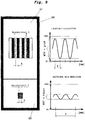
- Fig. 8 shows a display unit 30 having a first and a second display area 31, 32, as already described with reference to FIG Fig. 4 and 7 have been described.
- a main field of view is schematically represented by means of a line grid (gray levels represented by short ones in FIG Fig. 8 in the right-left direction running ropes on the black lines) as used in a modulation transfer function (MTF).
- the line grid represents the object contrast.
- a wide-angle field of view is represented schematically by means of a line grid.
- a measuring range Y is defined, which always comprises four lines.
- a measured value X is determined in each case, which in the main field of view and the wide angle field of view has an identical amount.
- the measured value X corresponds to the width of a line
- the measured value X corresponds to the width of four lines and thus the measuring range Y.
- the lines of both the line grid of the main field of view in the display area 31 and the wide angle field of view in the display area 32 extend in the image plane of FIG Fig. 8 top to bottom and have fixed distances.
- the modulation transfer function MTF is an evaluation criterion for incoherent mappings. More specifically, the modulation transfer function is a measure of the sharpness or contrast of the image and is defined as the ratio of image contrast to object contrast or the ratio of real image contrast to ideal image contrast.
- the sinusoidal image modulation represents the image contrast.
- the ratio of image contrast to object contrast in the main field of view is greater (high amplitude at low wavelength) than in the wide angle field of view (low amplitude at large wavelength).
- the measured value X in the sinusoidal image modulation of the main field of view thus comprises an extension of exactly half a wavelength, while the measured value X in the sinusoidal image modulation of the wide-angle field of view comprises exactly two wavelengths.
- the distance between the line pairs of the line grid of the main field of view is thus smaller than the distance between the line pairs of the line grid of the wide angle field of view, and therefore the main field of view always has a higher resolution than the wide angle field of view.
- modulation transfer function shown is one of many ways to describe the definition of an image and is the preferred mode of description herein. Of course, other types of resolutions are conceivable, such as the indication of the pixels per defined imaging surface.
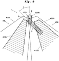
- Fig. 9 shows a top view of the vehicle 1 in which the tractor unit 2 and trailer 3 are no longer aligned in the longitudinal direction of the vehicle 1, but are arranged at an angle to each other, such as when cornering or turning the vehicle 1. More specifically, the trailer 3 is in one Angle ⁇ to the tractor unit 2 is arranged. Furthermore, at the in Fig. 9 In the embodiment shown, a sighting system 100L is arranged on the outside of the tractor unit 2 on the left in the main running direction, and a vision system 100R is arranged on the outside of the tractor unit 2 on the right in the main running direction.
- the vision systems 100L, 100R correspond to the vision system 100, but may also correspond to the vision system 200.
- the two vision systems 100L, 100R are designed such that they can exchange data with one another, such as image data, control commands, etc.
- the vision system 100 ⁇ / b> L receives an area of view 40 ⁇ / b> L of the surroundings on a left side of the vehicle 1 in the main traveling direction.
- the viewing area 40L includes a wide angle field of view 420L and a main field of view 410L.
- the vision system 100 ⁇ / b> R receives an area of view 40 ⁇ / b> R of the surroundings on a right side of the vehicle 1 in the main traveling direction.
- the viewing area 40R includes a wide angle field of view 420R and a main field of view 410R.
- Fig. 10 shows the receiving area or vision area 40L of the image sensor of the vision system 100L at Fig. 9 shown driving situation, ie when cornering or a turn.
- the viewing area 40L has the first image section 410L and the second image section 420L.
- the first image section 410L located at the Fig. 10 underlying driving situation, ie a cornering or a turning operation, the first image section 410L at a first modified position A2 ', while the second image section 420L is a second original position B2.
- the first image section 410L is at Fig.
- the reference point P2 is in the present case approximately in the center of a main direction of travel Positioned left edge of the end face 4, but can also be positioned at any other point of the end face 4.
- the reference point P2 allows the driver to position the trailer 3 in its left-hand surroundings and to estimate how large the angle ⁇ between the tractor unit 2 and the trailer 3 is.
- the in Fig. 10 The first image section 410L at the position A2 'no longer shows a main field of vision (not shown), but only the second image section 420L, which is also shown in FIG Fig. 10 underlying driving situation is still at the original position B2, also contains a (not shown) wide-angle field of view.
- Fig. 11 shows the receiving area or viewing area 40R of the image sensor of the vision system 100R at Fig. 9 shown driving situation, ie when cornering or a turn.
- the viewing area 40R has the first image section 410R and the second image section 420R.
- the first image section 410R located at the Fig. 11 underlying driving situation, ie a cornering or a turning operation, the first image section 410R at a first modified position A1 ', while the second image section 420R is a second original position B1.
- the first image section 410R is at Fig.
- the first image section 410R is taken from the field of view 40R at a position A1 'such that the first image section 410R contains a part of a trailer in the main travel direction of the trailer 3 and a reference point P1.
- the reference point P1 is presently arranged at an upper corner of the rear edge, but may also be positioned at any other point of the rear edge of the trailer 3 or another reference position.
- the reference point P1 allows the driver to place the trailer 3 in its immediate vicinity and to estimate how large the angle ⁇ between the tractor unit 2 and the trailer 3 is.
- the in Fig. 11 The first image section 410R at the position A1 'no longer shows a main field of vision (not shown), but only the second image section 420R, which is also shown in FIG Fig. 11 underlying driving situation is still at the original position B1, also contains a (not shown) wide-angle field of view.
- FIG. 15 shows a left vehicle environment reproducing reproducing unit 30L having a first display area 31L and a second display area 32L.
- the reproduction unit 30L corresponds to the reproduction unit 30 described above Fig. 12
- the second image section 420L corresponds to the second image section 420L at the original position B2.
- FIG. 12 shows a right vehicle environment reproducing unit 30R having a first display area 31R and a second display area 32R.
- the reproduction unit 30R corresponds to the reproduction unit 30 described above Fig. 13
- the second image section 420R corresponds to the second image section 420R at the original position B1.
- the left and right vehicle surroundings may also be displayed in a common display unit 30.
- both the left and right vision systems 100L, 100R displace the first image section 410L, 410R such that, even when the trailer 3 is extended relative to the tractor unit 2, the surroundings on the left and right sides around the vehicle are viewed by the driver can be.
Landscapes
- Engineering & Computer Science (AREA)
- Multimedia (AREA)
- Mechanical Engineering (AREA)
- Signal Processing (AREA)
- Chemical & Material Sciences (AREA)
- Combustion & Propulsion (AREA)
- Transportation (AREA)
- Closed-Circuit Television Systems (AREA)
- Studio Devices (AREA)
- Image Processing (AREA)
Applications Claiming Priority (1)
| Application Number | Priority Date | Filing Date | Title |
|---|---|---|---|
| DE102017130566.1A DE102017130566B4 (de) | 2017-12-19 | 2017-12-19 | Sichtsystem zur Erfassung einer Fahrzeugumgebung und Spiegelersatzsystem für ein Fahrzeug mit einem Sichtsystem |
Publications (2)
| Publication Number | Publication Date |
|---|---|
| EP3501897A1 true EP3501897A1 (fr) | 2019-06-26 |
| EP3501897B1 EP3501897B1 (fr) | 2020-12-30 |
Family
ID=64500178
Family Applications (1)
| Application Number | Title | Priority Date | Filing Date |
|---|---|---|---|
| EP18208430.1A Revoked EP3501897B1 (fr) | 2017-12-19 | 2018-11-27 | Système de visualisation permettant d'apprehender l'environnement d'un véhicule |
Country Status (7)
| Country | Link |
|---|---|
| US (2) | US11643011B2 (fr) |
| EP (1) | EP3501897B1 (fr) |
| JP (1) | JP6719540B2 (fr) |
| KR (1) | KR102150255B1 (fr) |
| CN (1) | CN109936730B (fr) |
| DE (1) | DE102017130566B4 (fr) |
| ES (1) | ES2861601T3 (fr) |
Cited By (2)
| Publication number | Priority date | Publication date | Assignee | Title |
|---|---|---|---|---|
| FR3139303A1 (fr) * | 2022-09-07 | 2024-03-08 | Safety Tech | Système de rétrovision avec caméras arrière |
| EP4382363A4 (fr) * | 2021-08-06 | 2025-04-30 | Shanghai Yuxing Electronics Technology Co., Ltd | Système d'affichage et procédé permettant de compenser la zone aveugle de champ de vision dans un rétroviseur d'un tracteur semi-remorque |
Families Citing this family (46)
| Publication number | Priority date | Publication date | Assignee | Title |
|---|---|---|---|---|
| WO2018125928A1 (fr) | 2016-12-29 | 2018-07-05 | DeepScale, Inc. | Simulation de capteur multicanal pour systèmes de commande autonomes |
| WO2018176000A1 (fr) | 2017-03-23 | 2018-09-27 | DeepScale, Inc. | Synthèse de données pour systèmes de commande autonomes |
| US11893393B2 (en) | 2017-07-24 | 2024-02-06 | Tesla, Inc. | Computational array microprocessor system with hardware arbiter managing memory requests |
| US11409692B2 (en) | 2017-07-24 | 2022-08-09 | Tesla, Inc. | Vector computational unit |
| US11157441B2 (en) | 2017-07-24 | 2021-10-26 | Tesla, Inc. | Computational array microprocessor system using non-consecutive data formatting |
| US10671349B2 (en) | 2017-07-24 | 2020-06-02 | Tesla, Inc. | Accelerated mathematical engine |
| US12307350B2 (en) | 2018-01-04 | 2025-05-20 | Tesla, Inc. | Systems and methods for hardware-based pooling |
| US11561791B2 (en) | 2018-02-01 | 2023-01-24 | Tesla, Inc. | Vector computational unit receiving data elements in parallel from a last row of a computational array |
| US11215999B2 (en) | 2018-06-20 | 2022-01-04 | Tesla, Inc. | Data pipeline and deep learning system for autonomous driving |
| US11636333B2 (en) | 2018-07-26 | 2023-04-25 | Tesla, Inc. | Optimizing neural network structures for embedded systems |
| US11562231B2 (en) | 2018-09-03 | 2023-01-24 | Tesla, Inc. | Neural networks for embedded devices |
| KR20250078625A (ko) | 2018-10-11 | 2025-06-02 | 테슬라, 인크. | 증강 데이터로 기계 모델을 훈련하기 위한 시스템 및 방법 |
| US11196678B2 (en) | 2018-10-25 | 2021-12-07 | Tesla, Inc. | QOS manager for system on a chip communications |
| US11816585B2 (en) | 2018-12-03 | 2023-11-14 | Tesla, Inc. | Machine learning models operating at different frequencies for autonomous vehicles |
| US11537811B2 (en) | 2018-12-04 | 2022-12-27 | Tesla, Inc. | Enhanced object detection for autonomous vehicles based on field view |
| US11345280B2 (en) * | 2018-12-19 | 2022-05-31 | Volvo Truck Corporation | Method for adapting an image displayed on a monitor in a vehicle cab to a vehicle configuration |
| US11610117B2 (en) | 2018-12-27 | 2023-03-21 | Tesla, Inc. | System and method for adapting a neural network model on a hardware platform |
| US11150664B2 (en) | 2019-02-01 | 2021-10-19 | Tesla, Inc. | Predicting three-dimensional features for autonomous driving |
| US10997461B2 (en) | 2019-02-01 | 2021-05-04 | Tesla, Inc. | Generating ground truth for machine learning from time series elements |
| US11567514B2 (en) | 2019-02-11 | 2023-01-31 | Tesla, Inc. | Autonomous and user controlled vehicle summon to a target |
| WO2020169693A1 (fr) | 2019-02-19 | 2020-08-27 | Orlaco Products B.V. | Système de remplacement de miroir avec assemblage dynamique |
| US10956755B2 (en) | 2019-02-19 | 2021-03-23 | Tesla, Inc. | Estimating object properties using visual image data |
| WO2021127199A1 (fr) * | 2019-12-17 | 2021-06-24 | Gentex Corporation | Système et procédé de capture et d'affichage d'images à partir d'une caméra de véhicule/remorque |
| DE102020000823A1 (de) | 2020-02-07 | 2021-08-12 | Scania Cv Ab | Verfahren und Steueranordnung für ein Gelenkfahrzeug |
| DE102020107789B4 (de) * | 2020-03-20 | 2025-04-03 | Mekra Lang Gmbh & Co. Kg | Sichtsystem für ein Fahrzeug und Verfahren zum Umschalten zwischen von dem Sichtsystem dargestellten Bildbereichen |
| EP3905655B1 (fr) * | 2020-04-30 | 2025-05-07 | Motherson Innovations Company Limited | Procédé d'alignement d'une caméra d'un système de surveillance de caméra de véhicule et véhicule |
| CN112389327A (zh) * | 2020-12-01 | 2021-02-23 | 哈尔滨北方防务装备股份有限公司 | 一种基于履带式双节车的驾驶感知系统 |
| TWI793477B (zh) * | 2020-12-04 | 2023-02-21 | 財團法人船舶暨海洋產業研發中心 | 船舶輔助校正系統及其運作方法 |
| US11890988B2 (en) * | 2021-04-05 | 2024-02-06 | Stoneridge, Inc. | Auto panning camera mirror system including image based trailer angle detection |
| CN113401059B (zh) * | 2021-08-06 | 2023-02-10 | 上海豫兴电子科技有限公司 | 一种用于挂车后视镜补偿视野盲区的显示系统及方法 |
| US12462575B2 (en) | 2021-08-19 | 2025-11-04 | Tesla, Inc. | Vision-based machine learning model for autonomous driving with adjustable virtual camera |
| WO2023023265A1 (fr) | 2021-08-19 | 2023-02-23 | Tesla, Inc. | Entraînement de système basé sur la vision avec un contenu simulé |
| US12049172B2 (en) * | 2021-10-19 | 2024-07-30 | Stoneridge, Inc. | Camera mirror system display for commercial vehicles including system for identifying road markings |
| US12260562B2 (en) * | 2021-10-19 | 2025-03-25 | Stoneridge, Inc. | Trailer end tracking in a camera monitoring system |
| EP4190637B1 (fr) * | 2021-12-02 | 2025-08-06 | Motherson Innovations Company Ltd. | Suivi de véhicule pour un système d'aile de caméra |
| CN114801996B (zh) * | 2022-04-02 | 2025-12-23 | 辉创电子科技(苏州)有限公司 | 一种电子侧后视镜随车转向扩大视野系统及其方法 |
| US11752943B1 (en) * | 2022-06-06 | 2023-09-12 | Stoneridge, Inc. | Auto panning camera monitoring system including image based trailer angle detection |
| JP7646603B2 (ja) * | 2022-06-30 | 2025-03-17 | キヤノン株式会社 | カメラモニタシステムおよびその制御方法、プログラム |
| DE102022131606A1 (de) * | 2022-11-29 | 2024-05-29 | Man Truck & Bus Se | Sichtsystem für ein Fahrzeug |
| US12157416B2 (en) * | 2022-12-15 | 2024-12-03 | GM Global Technology Operations LLC | System and method for enhancing occupant awareness |
| JP2024167770A (ja) * | 2023-05-22 | 2024-12-04 | アルプスアルパイン株式会社 | 後方映像表示システム |
| DE102023131359A1 (de) * | 2023-11-10 | 2025-05-15 | Mekra Lang Gmbh & Co. Kg | Kamerabasiertes System und Verfahren zum Bestimmen und Verifizieren der Position eines Anhängers |
| US12466323B2 (en) | 2024-01-11 | 2025-11-11 | Stoneridge Electronics Ab | Method and apparatus for determining trailer angle |
| DE102024120759B3 (de) | 2024-07-22 | 2025-10-30 | Mekra Lang Gmbh & Co. Kg | Indirektes Sichtsystem sowie Nutzfahrzeug mit Sichtsystem |
| US20260077717A1 (en) * | 2024-09-17 | 2026-03-19 | Stoneridge Electronics Ab | Camera monitor system including trailer-mounted camera |
| WO2026061608A1 (fr) * | 2024-09-17 | 2026-03-26 | Stoneridge Electronics Ab | Système de surveillance par caméra comprenant une caméra montée sur une remorque |
Citations (7)
| Publication number | Priority date | Publication date | Assignee | Title |
|---|---|---|---|---|
| DE102010032411A1 (de) * | 2010-07-27 | 2012-02-02 | Hans Dominik | Vorrichtung zur Überwachung der seitlichen und rückwärtigen Umgebung eines Fahrzeugs |
| EP2623374A1 (fr) * | 2012-01-31 | 2013-08-07 | MEKRA Lang GmbH & Co. KG | Système de vision pour véhicules utilitaires destiné à la représentation de champs de vision règlementaires d'un rétroviseur principal et d'un rétroviseur grand angle |
| DE102013214368A1 (de) * | 2013-07-23 | 2015-01-29 | Application Solutions (Electronics and Vision) Ltd. | Verfahren und Vorrichtung zur Wiedergabe eines seitlichen und/oder rückwärtigen Umgebungsbereichs eines Fahrzeugs |
| DE102013214369A1 (de) * | 2013-07-23 | 2015-01-29 | Application Solutions (Electronics and Vision) Ltd. | Verfahren und Vorrichtung zur Wiedergabe eines Umgebungsbereichs eines Fahrzeugs |
| DE102014006153A1 (de) * | 2014-04-25 | 2015-10-29 | Man Truck & Bus Ag | Verfahren zur Bilddarstellung eines indirekten Sichtfeldes im Fahrzeugumfeld eines Fahrzeugs, insbesondere eines Nutzfahrzeugs, mit einem Kamera-Monitor-System |
| DE102014018040A1 (de) * | 2014-12-05 | 2016-06-09 | Mekra Lang Gmbh & Co. Kg | Sichtsystem |
| DE102015218033A1 (de) * | 2015-09-18 | 2017-03-23 | Continental Automotive Gmbh | Verfahren zur Verbesserung der rückwärtigen Sicht in einem Kraftfahrzeug |
Family Cites Families (23)
| Publication number | Priority date | Publication date | Assignee | Title |
|---|---|---|---|---|
| JPH05258623A (ja) | 1992-03-10 | 1993-10-08 | Furukawa Electric Co Ltd:The | 超電導線の銅安定化層を電気メッキ法により形成する方法 |
| JP3436436B2 (ja) | 1995-03-22 | 2003-08-11 | 日産ディーゼル工業株式会社 | 車両の後方確認装置 |
| US6069581A (en) * | 1998-02-20 | 2000-05-30 | Amerigon | High performance vehicle radar system |
| US7425889B2 (en) | 2005-05-06 | 2008-09-16 | Delphi Technologies, Inc. | Vehicle turning assist system and method |
| US8446509B2 (en) * | 2006-08-09 | 2013-05-21 | Tenebraex Corporation | Methods of creating a virtual window |
| DE102007044536A1 (de) * | 2007-09-18 | 2009-03-19 | Bayerische Motoren Werke Aktiengesellschaft | Vorrichtung zum Überwachen der Umgebung eines Kraftfahrzeugs |
| US8416300B2 (en) * | 2009-05-20 | 2013-04-09 | International Business Machines Corporation | Traffic system for enhancing driver visibility |
| US8138899B2 (en) * | 2009-07-01 | 2012-03-20 | Ford Global Technologies, Llc | Rear camera backup assistance with touchscreen display using two points of interest |
| DE102010033786A1 (de) | 2010-07-06 | 2012-01-12 | Daimler Ag | Verfahren zur Erfassung und Anzeige seitlich neben und seitlich hinter einem Fahrzeug befindlicher Bereiche und Fahrzeug mit mehreren Bilderfassungseinheiten zur Erfassung seitlich neben und seitlich hinter dem Fahrzeug befindlicher Bereiche |
| CN201833953U (zh) * | 2010-10-09 | 2011-05-18 | 董利兵 | 牵引车可视雷达倒车装置 |
| CN103959334B (zh) * | 2011-11-28 | 2017-02-22 | 挂车有限公司 | 用于控制侧后视设备的调节的系统 |
| CN104885448B (zh) * | 2013-02-21 | 2018-04-06 | 本田技研工业株式会社 | 驾驶辅助装置以及图像处理程序 |
| US9367648B2 (en) * | 2013-03-14 | 2016-06-14 | Synopsys, Inc. | Specification-guided user interface for optical design systems |
| US20150115571A1 (en) * | 2013-10-24 | 2015-04-30 | GM Global Technology Operations LLC | Smart tow |
| CN104972980A (zh) * | 2014-04-03 | 2015-10-14 | 许佑正 | 车体转向侧照影像定点追踪辨识方法及其装置 |
| DE102014215372A1 (de) * | 2014-08-05 | 2016-02-11 | Conti Temic Microelectronic Gmbh | Fahrerassistenzsystem |
| JP6425991B2 (ja) | 2014-12-19 | 2018-11-21 | アルパイン株式会社 | 牽引車両周囲画像生成装置および牽引車両周囲画像生成方法 |
| DE102015002923B4 (de) | 2015-03-06 | 2023-01-12 | Mekra Lang Gmbh & Co. Kg | Anzeigeeinrichtung für ein Fahrzeug insbesondere Nutzfahrzeug |
| JP2016168877A (ja) * | 2015-03-11 | 2016-09-23 | 株式会社東海理化電機製作所 | 車両用視認装置 |
| DE102015014799A1 (de) * | 2015-11-13 | 2017-05-18 | Mekra Lang Gmbh & Co. Kg | System und Verfahren zur Erfassung eines Heckbereiches eines Fahrzeugs |
| DE102016003233A1 (de) * | 2016-03-16 | 2017-09-21 | Mekra Lang Gmbh & Co. Kg | Sichtsystem für ein Fahrzeug, insbesondere Nutzfahrzeug |
| US10259390B2 (en) * | 2016-05-27 | 2019-04-16 | GM Global Technology Operations LLC | Systems and methods for towing vehicle and trailer with surround view imaging devices |
| DE102017108569B4 (de) | 2017-04-21 | 2019-03-14 | Mekra Lang Gmbh & Co. Kg | Kamerasystem für ein Kraftfahrzeug, Spiegelersatzsystem mit einem solchen Kamerasystem und Fahrassistenzsystem mit einem solchen System |
-
2017
- 2017-12-19 DE DE102017130566.1A patent/DE102017130566B4/de active Active
-
2018
- 2018-11-27 EP EP18208430.1A patent/EP3501897B1/fr not_active Revoked
- 2018-11-27 ES ES18208430T patent/ES2861601T3/es active Active
- 2018-12-17 JP JP2018235032A patent/JP6719540B2/ja active Active
- 2018-12-17 US US16/222,811 patent/US11643011B2/en active Active
- 2018-12-18 CN CN201811552389.5A patent/CN109936730B/zh active Active
- 2018-12-19 KR KR1020180165669A patent/KR102150255B1/ko active Active
-
2023
- 2023-03-29 US US18/127,978 patent/US12151619B2/en active Active
Patent Citations (7)
| Publication number | Priority date | Publication date | Assignee | Title |
|---|---|---|---|---|
| DE102010032411A1 (de) * | 2010-07-27 | 2012-02-02 | Hans Dominik | Vorrichtung zur Überwachung der seitlichen und rückwärtigen Umgebung eines Fahrzeugs |
| EP2623374A1 (fr) * | 2012-01-31 | 2013-08-07 | MEKRA Lang GmbH & Co. KG | Système de vision pour véhicules utilitaires destiné à la représentation de champs de vision règlementaires d'un rétroviseur principal et d'un rétroviseur grand angle |
| DE102013214368A1 (de) * | 2013-07-23 | 2015-01-29 | Application Solutions (Electronics and Vision) Ltd. | Verfahren und Vorrichtung zur Wiedergabe eines seitlichen und/oder rückwärtigen Umgebungsbereichs eines Fahrzeugs |
| DE102013214369A1 (de) * | 2013-07-23 | 2015-01-29 | Application Solutions (Electronics and Vision) Ltd. | Verfahren und Vorrichtung zur Wiedergabe eines Umgebungsbereichs eines Fahrzeugs |
| DE102014006153A1 (de) * | 2014-04-25 | 2015-10-29 | Man Truck & Bus Ag | Verfahren zur Bilddarstellung eines indirekten Sichtfeldes im Fahrzeugumfeld eines Fahrzeugs, insbesondere eines Nutzfahrzeugs, mit einem Kamera-Monitor-System |
| DE102014018040A1 (de) * | 2014-12-05 | 2016-06-09 | Mekra Lang Gmbh & Co. Kg | Sichtsystem |
| DE102015218033A1 (de) * | 2015-09-18 | 2017-03-23 | Continental Automotive Gmbh | Verfahren zur Verbesserung der rückwärtigen Sicht in einem Kraftfahrzeug |
Cited By (3)
| Publication number | Priority date | Publication date | Assignee | Title |
|---|---|---|---|---|
| EP4382363A4 (fr) * | 2021-08-06 | 2025-04-30 | Shanghai Yuxing Electronics Technology Co., Ltd | Système d'affichage et procédé permettant de compenser la zone aveugle de champ de vision dans un rétroviseur d'un tracteur semi-remorque |
| FR3139303A1 (fr) * | 2022-09-07 | 2024-03-08 | Safety Tech | Système de rétrovision avec caméras arrière |
| WO2024052621A1 (fr) * | 2022-09-07 | 2024-03-14 | Safety Tech | Système de rétrovision avec caméras arrière |
Also Published As
| Publication number | Publication date |
|---|---|
| KR20190074268A (ko) | 2019-06-27 |
| US11643011B2 (en) | 2023-05-09 |
| JP6719540B2 (ja) | 2020-07-08 |
| EP3501897B1 (fr) | 2020-12-30 |
| DE102017130566B4 (de) | 2021-07-22 |
| US20190184900A1 (en) | 2019-06-20 |
| ES2861601T3 (es) | 2021-10-06 |
| CN109936730A (zh) | 2019-06-25 |
| KR102150255B1 (ko) | 2020-09-01 |
| JP2019142481A (ja) | 2019-08-29 |
| CN109936730B (zh) | 2021-06-08 |
| US20230234501A1 (en) | 2023-07-27 |
| US12151619B2 (en) | 2024-11-26 |
| DE102017130566A1 (de) | 2019-06-19 |
Similar Documents
| Publication | Publication Date | Title |
|---|---|---|
| EP3501897B1 (fr) | Système de visualisation permettant d'apprehender l'environnement d'un véhicule | |
| EP3029929B1 (fr) | Systeme de vision | |
| DE102006003538B3 (de) | Verfahren zum Zusammenfügen mehrerer Bildaufnahmen zu einem Gesamtbild in der Vogelperspektive | |
| EP3219533B1 (fr) | Système de vision pour un véhicule, notamment pour un véhicule utilitaire | |
| EP2484558B1 (fr) | Dispositif d'affichage pour champs de vision d'un véhicule utilitaire | |
| EP3528026B1 (fr) | Système de caméra pour un véhicule automobile, système de remplacement de miroir doté d'un tel système de caméra et système d'aide à la conduite doté d'un tel système | |
| EP3024700B1 (fr) | Procédé et dispositif permettant de reproduire une zone latérale et/ou arrière environnant un véhicule | |
| EP2765031B1 (fr) | Système de vision pour véhicules, notamment véhicules utilitaires | |
| EP1211132B1 (fr) | Dispositif et procédé pour surveiller l'environnement d'un véhicule | |
| DE102012025322B4 (de) | Kraftfahrzeug mit Kamera-Monitor-System | |
| DE102010032411A1 (de) | Vorrichtung zur Überwachung der seitlichen und rückwärtigen Umgebung eines Fahrzeugs | |
| EP3012154B1 (fr) | Procédé et dispositif d'assistance d'un conducteur d'un attelage, notamment d'un attelage de véhicule utilitaire | |
| DE102010051206A1 (de) | Verfahren zum Erzeugen eines Bilds einer Fahrzeugumgebung und Abbildungsvorrichtung | |
| EP2483107B1 (fr) | Procédé et dispositif d'affichage visuel combiné de données vidéo et de données de distance d'une situation de circulation | |
| EP2791895A1 (fr) | Procédé permettant d'améliorer la détection d'un objet par des systèmes multi-caméras | |
| EP2500216A1 (fr) | Procédé et dispositif pour un système d'assistance au conducteur produisant des images | |
| DE102013214369A1 (de) | Verfahren und Vorrichtung zur Wiedergabe eines Umgebungsbereichs eines Fahrzeugs | |
| EP3833576B1 (fr) | Systeme de camera de surveillance | |
| EP3041710B1 (fr) | Methode pour la maneuvre un vehicule | |
| EP2804785B1 (fr) | Système d'affichage destiné à un véhicule | |
| EP4553771A1 (fr) | Système basé sur une caméra et procédé de détermination et de vérification de la position d'une remorque |
Legal Events
| Date | Code | Title | Description |
|---|---|---|---|
| PUAI | Public reference made under article 153(3) epc to a published international application that has entered the european phase |
Free format text: ORIGINAL CODE: 0009012 |
|
| STAA | Information on the status of an ep patent application or granted ep patent |
Free format text: STATUS: REQUEST FOR EXAMINATION WAS MADE |
|
| 17P | Request for examination filed |
Effective date: 20181127 |
|
| AK | Designated contracting states |
Kind code of ref document: A1 Designated state(s): AL AT BE BG CH CY CZ DE DK EE ES FI FR GB GR HR HU IE IS IT LI LT LU LV MC MK MT NL NO PL PT RO RS SE SI SK SM TR |
|
| AX | Request for extension of the european patent |
Extension state: BA ME |
|
| STAA | Information on the status of an ep patent application or granted ep patent |
Free format text: STATUS: EXAMINATION IS IN PROGRESS |
|
| 17Q | First examination report despatched |
Effective date: 20200117 |
|
| GRAP | Despatch of communication of intention to grant a patent |
Free format text: ORIGINAL CODE: EPIDOSNIGR1 |
|
| STAA | Information on the status of an ep patent application or granted ep patent |
Free format text: STATUS: GRANT OF PATENT IS INTENDED |
|
| INTG | Intention to grant announced |
Effective date: 20200619 |
|
| GRAJ | Information related to disapproval of communication of intention to grant by the applicant or resumption of examination proceedings by the epo deleted |
Free format text: ORIGINAL CODE: EPIDOSDIGR1 |
|
| STAA | Information on the status of an ep patent application or granted ep patent |
Free format text: STATUS: EXAMINATION IS IN PROGRESS |
|
| INTC | Intention to grant announced (deleted) | ||
| GRAP | Despatch of communication of intention to grant a patent |
Free format text: ORIGINAL CODE: EPIDOSNIGR1 |
|
| STAA | Information on the status of an ep patent application or granted ep patent |
Free format text: STATUS: GRANT OF PATENT IS INTENDED |
|
| GRAS | Grant fee paid |
Free format text: ORIGINAL CODE: EPIDOSNIGR3 |
|
| INTG | Intention to grant announced |
Effective date: 20201014 |
|
| GRAA | (expected) grant |
Free format text: ORIGINAL CODE: 0009210 |
|
| STAA | Information on the status of an ep patent application or granted ep patent |
Free format text: STATUS: THE PATENT HAS BEEN GRANTED |
|
| AK | Designated contracting states |
Kind code of ref document: B1 Designated state(s): AL AT BE BG CH CY CZ DE DK EE ES FI FR GB GR HR HU IE IS IT LI LT LU LV MC MK MT NL NO PL PT RO RS SE SI SK SM TR |
|
| REG | Reference to a national code |
Ref country code: GB Ref legal event code: FG4D Free format text: NOT ENGLISH |
|
| REG | Reference to a national code |
Ref country code: AT Ref legal event code: REF Ref document number: 1349626 Country of ref document: AT Kind code of ref document: T Effective date: 20210115 |
|
| REG | Reference to a national code |
Ref country code: DE Ref legal event code: R096 Ref document number: 502018003472 Country of ref document: DE |
|
| REG | Reference to a national code |
Ref country code: IE Ref legal event code: FG4D Free format text: LANGUAGE OF EP DOCUMENT: GERMAN |
|
| REG | Reference to a national code |
Ref country code: NL Ref legal event code: FP |
|
| REG | Reference to a national code |
Ref country code: SE Ref legal event code: TRGR |
|
| PG25 | Lapsed in a contracting state [announced via postgrant information from national office to epo] |
Ref country code: FI Free format text: LAPSE BECAUSE OF FAILURE TO SUBMIT A TRANSLATION OF THE DESCRIPTION OR TO PAY THE FEE WITHIN THE PRESCRIBED TIME-LIMIT Effective date: 20201230 Ref country code: RS Free format text: LAPSE BECAUSE OF FAILURE TO SUBMIT A TRANSLATION OF THE DESCRIPTION OR TO PAY THE FEE WITHIN THE PRESCRIBED TIME-LIMIT Effective date: 20201230 Ref country code: GR Free format text: LAPSE BECAUSE OF FAILURE TO SUBMIT A TRANSLATION OF THE DESCRIPTION OR TO PAY THE FEE WITHIN THE PRESCRIBED TIME-LIMIT Effective date: 20210331 Ref country code: NO Free format text: LAPSE BECAUSE OF FAILURE TO SUBMIT A TRANSLATION OF THE DESCRIPTION OR TO PAY THE FEE WITHIN THE PRESCRIBED TIME-LIMIT Effective date: 20210330 |
|
| PG25 | Lapsed in a contracting state [announced via postgrant information from national office to epo] |
Ref country code: BG Free format text: LAPSE BECAUSE OF FAILURE TO SUBMIT A TRANSLATION OF THE DESCRIPTION OR TO PAY THE FEE WITHIN THE PRESCRIBED TIME-LIMIT Effective date: 20210330 Ref country code: LV Free format text: LAPSE BECAUSE OF FAILURE TO SUBMIT A TRANSLATION OF THE DESCRIPTION OR TO PAY THE FEE WITHIN THE PRESCRIBED TIME-LIMIT Effective date: 20201230 |
|
| PG25 | Lapsed in a contracting state [announced via postgrant information from national office to epo] |
Ref country code: HR Free format text: LAPSE BECAUSE OF FAILURE TO SUBMIT A TRANSLATION OF THE DESCRIPTION OR TO PAY THE FEE WITHIN THE PRESCRIBED TIME-LIMIT Effective date: 20201230 |
|
| REG | Reference to a national code |
Ref country code: LT Ref legal event code: MG9D |
|
| PG25 | Lapsed in a contracting state [announced via postgrant information from national office to epo] |
Ref country code: SK Free format text: LAPSE BECAUSE OF FAILURE TO SUBMIT A TRANSLATION OF THE DESCRIPTION OR TO PAY THE FEE WITHIN THE PRESCRIBED TIME-LIMIT Effective date: 20201230 Ref country code: EE Free format text: LAPSE BECAUSE OF FAILURE TO SUBMIT A TRANSLATION OF THE DESCRIPTION OR TO PAY THE FEE WITHIN THE PRESCRIBED TIME-LIMIT Effective date: 20201230 Ref country code: CZ Free format text: LAPSE BECAUSE OF FAILURE TO SUBMIT A TRANSLATION OF THE DESCRIPTION OR TO PAY THE FEE WITHIN THE PRESCRIBED TIME-LIMIT Effective date: 20201230 Ref country code: PT Free format text: LAPSE BECAUSE OF FAILURE TO SUBMIT A TRANSLATION OF THE DESCRIPTION OR TO PAY THE FEE WITHIN THE PRESCRIBED TIME-LIMIT Effective date: 20210430 Ref country code: RO Free format text: LAPSE BECAUSE OF FAILURE TO SUBMIT A TRANSLATION OF THE DESCRIPTION OR TO PAY THE FEE WITHIN THE PRESCRIBED TIME-LIMIT Effective date: 20201230 Ref country code: LT Free format text: LAPSE BECAUSE OF FAILURE TO SUBMIT A TRANSLATION OF THE DESCRIPTION OR TO PAY THE FEE WITHIN THE PRESCRIBED TIME-LIMIT Effective date: 20201230 |
|
| PG25 | Lapsed in a contracting state [announced via postgrant information from national office to epo] |
Ref country code: PL Free format text: LAPSE BECAUSE OF FAILURE TO SUBMIT A TRANSLATION OF THE DESCRIPTION OR TO PAY THE FEE WITHIN THE PRESCRIBED TIME-LIMIT Effective date: 20201230 |
|
| PG25 | Lapsed in a contracting state [announced via postgrant information from national office to epo] |
Ref country code: IS Free format text: LAPSE BECAUSE OF FAILURE TO SUBMIT A TRANSLATION OF THE DESCRIPTION OR TO PAY THE FEE WITHIN THE PRESCRIBED TIME-LIMIT Effective date: 20210430 |
|
| REG | Reference to a national code |
Ref country code: DE Ref legal event code: R026 Ref document number: 502018003472 Country of ref document: DE |
|
| REG | Reference to a national code |
Ref country code: ES Ref legal event code: FG2A Ref document number: 2861601 Country of ref document: ES Kind code of ref document: T3 Effective date: 20211006 |
|
| PLBI | Opposition filed |
Free format text: ORIGINAL CODE: 0009260 |
|
| PLAX | Notice of opposition and request to file observation + time limit sent |
Free format text: ORIGINAL CODE: EPIDOSNOBS2 |
|
| PG25 | Lapsed in a contracting state [announced via postgrant information from national office to epo] |
Ref country code: AL Free format text: LAPSE BECAUSE OF FAILURE TO SUBMIT A TRANSLATION OF THE DESCRIPTION OR TO PAY THE FEE WITHIN THE PRESCRIBED TIME-LIMIT Effective date: 20201230 |
|
| 26 | Opposition filed |
Opponent name: STONERIDGE ELECTRONICS AB Effective date: 20210930 |
|
| PG25 | Lapsed in a contracting state [announced via postgrant information from national office to epo] |
Ref country code: DK Free format text: LAPSE BECAUSE OF FAILURE TO SUBMIT A TRANSLATION OF THE DESCRIPTION OR TO PAY THE FEE WITHIN THE PRESCRIBED TIME-LIMIT Effective date: 20201230 |
|
| PLBB | Reply of patent proprietor to notice(s) of opposition received |
Free format text: ORIGINAL CODE: EPIDOSNOBS3 |
|
| PG25 | Lapsed in a contracting state [announced via postgrant information from national office to epo] |
Ref country code: SI Free format text: LAPSE BECAUSE OF FAILURE TO SUBMIT A TRANSLATION OF THE DESCRIPTION OR TO PAY THE FEE WITHIN THE PRESCRIBED TIME-LIMIT Effective date: 20201230 |
|
| PG25 | Lapsed in a contracting state [announced via postgrant information from national office to epo] |
Ref country code: IS Free format text: LAPSE BECAUSE OF FAILURE TO SUBMIT A TRANSLATION OF THE DESCRIPTION OR TO PAY THE FEE WITHIN THE PRESCRIBED TIME-LIMIT Effective date: 20210430 |
|
| PG25 | Lapsed in a contracting state [announced via postgrant information from national office to epo] |
Ref country code: MC Free format text: LAPSE BECAUSE OF FAILURE TO SUBMIT A TRANSLATION OF THE DESCRIPTION OR TO PAY THE FEE WITHIN THE PRESCRIBED TIME-LIMIT Effective date: 20201230 |
|
| REG | Reference to a national code |
Ref country code: CH Ref legal event code: PL |
|
| PG25 | Lapsed in a contracting state [announced via postgrant information from national office to epo] |
Ref country code: LU Free format text: LAPSE BECAUSE OF NON-PAYMENT OF DUE FEES Effective date: 20211127 Ref country code: BE Free format text: LAPSE BECAUSE OF NON-PAYMENT OF DUE FEES Effective date: 20211130 |
|
| REG | Reference to a national code |
Ref country code: BE Ref legal event code: MM Effective date: 20211130 |
|
| PG25 | Lapsed in a contracting state [announced via postgrant information from national office to epo] |
Ref country code: IE Free format text: LAPSE BECAUSE OF NON-PAYMENT OF DUE FEES Effective date: 20211127 |
|
| P01 | Opt-out of the competence of the unified patent court (upc) registered |
Effective date: 20230426 |
|
| PG25 | Lapsed in a contracting state [announced via postgrant information from national office to epo] |
Ref country code: CY Free format text: LAPSE BECAUSE OF FAILURE TO SUBMIT A TRANSLATION OF THE DESCRIPTION OR TO PAY THE FEE WITHIN THE PRESCRIBED TIME-LIMIT Effective date: 20201230 |
|
| PG25 | Lapsed in a contracting state [announced via postgrant information from national office to epo] |
Ref country code: SM Free format text: LAPSE BECAUSE OF FAILURE TO SUBMIT A TRANSLATION OF THE DESCRIPTION OR TO PAY THE FEE WITHIN THE PRESCRIBED TIME-LIMIT Effective date: 20201230 Ref country code: LI Free format text: LAPSE BECAUSE OF NON-PAYMENT OF DUE FEES Effective date: 20220701 Ref country code: HU Free format text: LAPSE BECAUSE OF FAILURE TO SUBMIT A TRANSLATION OF THE DESCRIPTION OR TO PAY THE FEE WITHIN THE PRESCRIBED TIME-LIMIT; INVALID AB INITIO Effective date: 20181127 Ref country code: CH Free format text: LAPSE BECAUSE OF NON-PAYMENT OF DUE FEES Effective date: 20220701 |
|
| REG | Reference to a national code |
Ref country code: DE Ref legal event code: R082 Ref document number: 502018003472 Country of ref document: DE Representative=s name: ALPSPITZ IP ALLGAYER UND PARTNER PATENTANWAELT, DE |
|
| APAH | Appeal reference modified |
Free format text: ORIGINAL CODE: EPIDOSCREFNO |
|
| APBM | Appeal reference recorded |
Free format text: ORIGINAL CODE: EPIDOSNREFNO |
|
| APBP | Date of receipt of notice of appeal recorded |
Free format text: ORIGINAL CODE: EPIDOSNNOA2O |
|
| APBM | Appeal reference recorded |
Free format text: ORIGINAL CODE: EPIDOSNREFNO |
|
| APBP | Date of receipt of notice of appeal recorded |
Free format text: ORIGINAL CODE: EPIDOSNNOA2O |
|
| APBQ | Date of receipt of statement of grounds of appeal recorded |
Free format text: ORIGINAL CODE: EPIDOSNNOA3O |
|
| APBQ | Date of receipt of statement of grounds of appeal recorded |
Free format text: ORIGINAL CODE: EPIDOSNNOA3O |
|
| PGFP | Annual fee paid to national office [announced via postgrant information from national office to epo] |
Ref country code: NL Payment date: 20231122 Year of fee payment: 6 |
|
| PGFP | Annual fee paid to national office [announced via postgrant information from national office to epo] |
Ref country code: GB Payment date: 20231123 Year of fee payment: 6 |
|
| PGFP | Annual fee paid to national office [announced via postgrant information from national office to epo] |
Ref country code: ES Payment date: 20231215 Year of fee payment: 6 |
|
| PGFP | Annual fee paid to national office [announced via postgrant information from national office to epo] |
Ref country code: TR Payment date: 20231120 Year of fee payment: 6 Ref country code: SE Payment date: 20231123 Year of fee payment: 6 Ref country code: FR Payment date: 20231124 Year of fee payment: 6 Ref country code: DE Payment date: 20231120 Year of fee payment: 6 Ref country code: IT Payment date: 20231130 Year of fee payment: 6 |
|
| PG25 | Lapsed in a contracting state [announced via postgrant information from national office to epo] |
Ref country code: MK Free format text: LAPSE BECAUSE OF FAILURE TO SUBMIT A TRANSLATION OF THE DESCRIPTION OR TO PAY THE FEE WITHIN THE PRESCRIBED TIME-LIMIT Effective date: 20201230 |
|
| PG25 | Lapsed in a contracting state [announced via postgrant information from national office to epo] |
Ref country code: MT Free format text: LAPSE BECAUSE OF FAILURE TO SUBMIT A TRANSLATION OF THE DESCRIPTION OR TO PAY THE FEE WITHIN THE PRESCRIBED TIME-LIMIT Effective date: 20201230 |
|
| REG | Reference to a national code |
Ref country code: AT Ref legal event code: MM01 Ref document number: 1349626 Country of ref document: AT Kind code of ref document: T Effective date: 20231127 |
|
| PG25 | Lapsed in a contracting state [announced via postgrant information from national office to epo] |
Ref country code: AT Free format text: LAPSE BECAUSE OF NON-PAYMENT OF DUE FEES Effective date: 20231127 |
|
| PG25 | Lapsed in a contracting state [announced via postgrant information from national office to epo] |
Ref country code: AT Free format text: LAPSE BECAUSE OF NON-PAYMENT OF DUE FEES Effective date: 20231127 |
|
| APBU | Appeal procedure closed |
Free format text: ORIGINAL CODE: EPIDOSNNOA9O |
|
| REG | Reference to a national code |
Ref country code: DE Ref legal event code: R103 Ref document number: 502018003472 Country of ref document: DE Ref country code: DE Ref legal event code: R064 Ref document number: 502018003472 Country of ref document: DE |
|
| RDAF | Communication despatched that patent is revoked |
Free format text: ORIGINAL CODE: EPIDOSNREV1 |
|
| STAA | Information on the status of an ep patent application or granted ep patent |
Free format text: STATUS: PATENT REVOKED |
|
| RDAG | Patent revoked |
Free format text: ORIGINAL CODE: 0009271 |
|
| REG | Reference to a national code |
Ref country code: CH Ref legal event code: PL |
|
| REG | Reference to a national code |
Ref country code: SE Ref legal event code: EUG |
|
| REG | Reference to a national code |
Ref country code: NL Ref legal event code: MM Effective date: 20241201 |
|
| REG | Reference to a national code |
Ref country code: CH Ref legal event code: PL |
|
| 27W | Patent revoked |
Effective date: 20250528 |
|
| GBPR | Gb: patent revoked under art. 102 of the ep convention designating the uk as contracting state |
Effective date: 20250528 |
|
| PG25 | Lapsed in a contracting state [announced via postgrant information from national office to epo] |
Ref country code: NL Free format text: LAPSE BECAUSE OF NON-PAYMENT OF DUE FEES Effective date: 20241201 |
|
| REG | Reference to a national code |
Ref country code: AT Ref legal event code: MA03 Ref document number: 1349626 Country of ref document: AT Kind code of ref document: T Effective date: 20250528 |
|
| PG25 | Lapsed in a contracting state [announced via postgrant information from national office to epo] |
Ref country code: SE Free format text: LAPSE BECAUSE OF NON-PAYMENT OF DUE FEES Effective date: 20241128 |
|
| PGFP | Annual fee paid to national office [announced via postgrant information from national office to epo] |
Ref country code: AT Payment date: 20260410 Year of fee payment: 5 |