EP1504976A1 - Soupape de freinage pour un remorque - Google Patents
Soupape de freinage pour un remorque Download PDFInfo
- Publication number
- EP1504976A1 EP1504976A1 EP04017793A EP04017793A EP1504976A1 EP 1504976 A1 EP1504976 A1 EP 1504976A1 EP 04017793 A EP04017793 A EP 04017793A EP 04017793 A EP04017793 A EP 04017793A EP 1504976 A1 EP1504976 A1 EP 1504976A1
- Authority
- EP
- European Patent Office
- Prior art keywords
- valve
- brake
- trailer
- check valve
- piston
- Prior art date
- Legal status (The legal status is an assumption and is not a legal conclusion. Google has not performed a legal analysis and makes no representation as to the accuracy of the status listed.)
- Granted
Links
- 238000013022 venting Methods 0.000 claims description 4
- 230000000694 effects Effects 0.000 description 9
- 230000008878 coupling Effects 0.000 description 8
- 238000010168 coupling process Methods 0.000 description 8
- 238000005859 coupling reaction Methods 0.000 description 8
- 230000006870 function Effects 0.000 description 7
- 230000009471 action Effects 0.000 description 5
- 238000007789 sealing Methods 0.000 description 5
- 230000001419 dependent effect Effects 0.000 description 3
- 230000008901 benefit Effects 0.000 description 2
- 230000005540 biological transmission Effects 0.000 description 2
- 230000007423 decrease Effects 0.000 description 2
- 230000004913 activation Effects 0.000 description 1
- 230000033228 biological regulation Effects 0.000 description 1
- 238000006073 displacement reaction Methods 0.000 description 1
- 238000004090 dissolution Methods 0.000 description 1
- 210000003746 feather Anatomy 0.000 description 1
- 238000004519 manufacturing process Methods 0.000 description 1
- 230000036544 posture Effects 0.000 description 1
- 230000008054 signal transmission Effects 0.000 description 1
- 230000003319 supportive effect Effects 0.000 description 1
Images




Classifications
-
- B—PERFORMING OPERATIONS; TRANSPORTING
- B60—VEHICLES IN GENERAL
- B60T—VEHICLE BRAKE CONTROL SYSTEMS OR PARTS THEREOF; BRAKE CONTROL SYSTEMS OR PARTS THEREOF, IN GENERAL; ARRANGEMENT OF BRAKING ELEMENTS ON VEHICLES IN GENERAL; PORTABLE DEVICES FOR PREVENTING UNWANTED MOVEMENT OF VEHICLES; VEHICLE MODIFICATIONS TO FACILITATE COOLING OF BRAKES
- B60T15/00—Construction arrangement, or operation of valves incorporated in power brake systems and not covered by groups B60T11/00 or B60T13/00
- B60T15/02—Application and release valves
- B60T15/18—Triple or other relay valves which allow step-wise application or release and which are actuated by brake-pipe pressure variation to connect brake cylinders or equivalent to compressed air or vacuum source or atmosphere
- B60T15/20—Triple or other relay valves which allow step-wise application or release and which are actuated by brake-pipe pressure variation to connect brake cylinders or equivalent to compressed air or vacuum source or atmosphere controlled by two fluid pressures
- B60T15/22—Triple or other relay valves which allow step-wise application or release and which are actuated by brake-pipe pressure variation to connect brake cylinders or equivalent to compressed air or vacuum source or atmosphere controlled by two fluid pressures with one or more auxiliary valves, for braking, releasing, filling reservoirs
- B60T15/223—Trailer control valves
-
- B—PERFORMING OPERATIONS; TRANSPORTING
- B60—VEHICLES IN GENERAL
- B60T—VEHICLE BRAKE CONTROL SYSTEMS OR PARTS THEREOF; BRAKE CONTROL SYSTEMS OR PARTS THEREOF, IN GENERAL; ARRANGEMENT OF BRAKING ELEMENTS ON VEHICLES IN GENERAL; PORTABLE DEVICES FOR PREVENTING UNWANTED MOVEMENT OF VEHICLES; VEHICLE MODIFICATIONS TO FACILITATE COOLING OF BRAKES
- B60T13/00—Transmitting braking action from initiating means to ultimate brake actuator with power assistance or drive; Brake systems incorporating such transmitting means, e.g. air-pressure brake systems
- B60T13/10—Transmitting braking action from initiating means to ultimate brake actuator with power assistance or drive; Brake systems incorporating such transmitting means, e.g. air-pressure brake systems with fluid assistance, drive, or release
- B60T13/24—Transmitting braking action from initiating means to ultimate brake actuator with power assistance or drive; Brake systems incorporating such transmitting means, e.g. air-pressure brake systems with fluid assistance, drive, or release the fluid being gaseous
- B60T13/26—Compressed-air systems
- B60T13/261—Compressed-air systems systems with both indirect application and application by springs or weights and released by compressed air
- B60T13/265—Compressed-air systems systems with both indirect application and application by springs or weights and released by compressed air dependent systems, e.g. trailer systems
-
- B—PERFORMING OPERATIONS; TRANSPORTING
- B60—VEHICLES IN GENERAL
- B60T—VEHICLE BRAKE CONTROL SYSTEMS OR PARTS THEREOF; BRAKE CONTROL SYSTEMS OR PARTS THEREOF, IN GENERAL; ARRANGEMENT OF BRAKING ELEMENTS ON VEHICLES IN GENERAL; PORTABLE DEVICES FOR PREVENTING UNWANTED MOVEMENT OF VEHICLES; VEHICLE MODIFICATIONS TO FACILITATE COOLING OF BRAKES
- B60T13/00—Transmitting braking action from initiating means to ultimate brake actuator with power assistance or drive; Brake systems incorporating such transmitting means, e.g. air-pressure brake systems
- B60T13/10—Transmitting braking action from initiating means to ultimate brake actuator with power assistance or drive; Brake systems incorporating such transmitting means, e.g. air-pressure brake systems with fluid assistance, drive, or release
- B60T13/24—Transmitting braking action from initiating means to ultimate brake actuator with power assistance or drive; Brake systems incorporating such transmitting means, e.g. air-pressure brake systems with fluid assistance, drive, or release the fluid being gaseous
- B60T13/26—Compressed-air systems
- B60T13/38—Brakes applied by springs or weights and released by compressed air
- B60T13/385—Control arrangements therefor
-
- B—PERFORMING OPERATIONS; TRANSPORTING
- B60—VEHICLES IN GENERAL
- B60T—VEHICLE BRAKE CONTROL SYSTEMS OR PARTS THEREOF; BRAKE CONTROL SYSTEMS OR PARTS THEREOF, IN GENERAL; ARRANGEMENT OF BRAKING ELEMENTS ON VEHICLES IN GENERAL; PORTABLE DEVICES FOR PREVENTING UNWANTED MOVEMENT OF VEHICLES; VEHICLE MODIFICATIONS TO FACILITATE COOLING OF BRAKES
- B60T15/00—Construction arrangement, or operation of valves incorporated in power brake systems and not covered by groups B60T11/00 or B60T13/00
- B60T15/02—Application and release valves
- B60T15/18—Triple or other relay valves which allow step-wise application or release and which are actuated by brake-pipe pressure variation to connect brake cylinders or equivalent to compressed air or vacuum source or atmosphere
- B60T15/20—Triple or other relay valves which allow step-wise application or release and which are actuated by brake-pipe pressure variation to connect brake cylinders or equivalent to compressed air or vacuum source or atmosphere controlled by two fluid pressures
- B60T15/203—Trailer control valves
-
- B—PERFORMING OPERATIONS; TRANSPORTING
- B60—VEHICLES IN GENERAL
- B60T—VEHICLE BRAKE CONTROL SYSTEMS OR PARTS THEREOF; BRAKE CONTROL SYSTEMS OR PARTS THEREOF, IN GENERAL; ARRANGEMENT OF BRAKING ELEMENTS ON VEHICLES IN GENERAL; PORTABLE DEVICES FOR PREVENTING UNWANTED MOVEMENT OF VEHICLES; VEHICLE MODIFICATIONS TO FACILITATE COOLING OF BRAKES
- B60T15/00—Construction arrangement, or operation of valves incorporated in power brake systems and not covered by groups B60T11/00 or B60T13/00
- B60T15/02—Application and release valves
- B60T15/36—Other control devices or valves characterised by definite functions
- B60T15/60—Other control devices or valves characterised by definite functions for releasing or applying brakes when vehicles of a vehicle train are uncoupled
Definitions
- the invention relates to a trailer brake valve having a housing having an input port for a supply line, an inlet connection for a brake line, a Connection for a reservoir, an output port for a brake control pressure for service brake cylinder and an output port for one to spring brake cylinders leading release line has, with an emergency braking device, the one Piston arrangement with an acted upon by the pressure in the reservoir switching piston and one of the release line associated with the spring brake cylinders check valve and in the case of pressure-free supply line the reservoir with the output port for the brake control pressure connects.
- Such trailer brake valves are known to be used on trailers, the trailer usually with combination cylinders equipped with a spring storage part with release chamber and storage spring and a Have service brake with brake chamber.
- the trailer brake valve has in a housing on a control piston, the Part of an emergency braking device is.
- the control piston as part of the emergency brake is not designed here as a relay piston.
- the protection of the supply pressure in a reservoir on the trailer via a check valve in the Supply line.
- unpressurized supply line of the switching piston connects the reservoir with an output port for the brake control pressure.
- the release line to the Spring brake cylinders is arranged another check valve. This check valve is required to the release pressure in the release chamber of the spring-loaded part maintain, so that occurring pressure fluctuations in the reservoir, the caused by normal braking, an additional occurring Braking effect on the spring accumulator part is avoided.
- the in the release chamber of the Spring brake arranged check valve has a supported on a spring Plate on which in turn is mounted in a piston, which is also on a spring is supported. It is a non-return valve controlled by pressure, d. H. the check valve opens only after a pressure drop of defined size in Reservoir. In off uncoupled state of the trailer is known to be the Supply line vented. It enters the emergency brake position by the pressure in Reservoir is controlled via the control line to the relay valve. Subsequently occurs a braking effect on the service brake cylinder. If in such a case the Reservoir creeping air loses the braking effect in the service brake cylinders accordingly, without any supportive effect by the spring brake cylinder entry.
- the remaining braking force can be less than that Braking force sufficient to lock the trailer in uncoupled off state hold. Only when the pressure in the reservoir has dropped further, so one Pressure drop threshold has been exceeded, opens the pressure-controlled check valve in the leading to the release chamber of the spring brake cylinder release line and it creates a connection between the reservoir and the release chamber of the Spring brake part. Then the pressure goes down together. Depending on where the Switching pressure of the spring brake is, the spring accumulator is activated. Of the Trailer could be rolled away in the meantime. But then he will, after one Lowering the pressure in the reservoir, at which the lower pressure of the pressure drop threshold is fallen below, braked by the spring brake. With these uncertainties the system of the trailer brake valve is loaded. The known plant is silent to the Possibility of arranging a manually operated parking valve and / or a Maneuvering valve and the associated problems resulting from the pressing or non-actuation (forgetting) of the parking valve.
- the trailer brake valve has a housing with the usual connections for the brake line, the Supply line, an output brake control pressure for operating brake cylinders, either directly or influenced by a pressure modulator. It is also one Connection for a reservoir for compressed air provided on the trailer. After all The trailer brake valve is also intended for such a brake system, in addition to the service brake cylinders has spring brake cylinder, which has a Release line to be kept dissolved.
- the trailer brake valve has in its housing only an emergency braking device and thus waives the arrangement of a Relay piston. The emergency brake device connects the pressure-free supply line Reservoir with the output port for the brake control pressure in the service brake cylinder.
- the emergency brake device has a piston assembly with one of the pressure in the reservoir acted upon switching piston. Furthermore, in the trailer brake valve a check valve is provided, which is the release line to the spring brake cylinders assigned. It is understood that the filling and securing of the Reservoir via a second check valve, which is often as überströmbare Lip cuff is formed.
- a trailer brake valve on the trailer can operated together with a braking system on the motor vehicle, the whole may be formed differently, ranging from a simple mechanical-pneumatic Brake system up to a substantial electronic elements having Brake system with ABS and / or EBS control. It is known that in connection with it usable trailer brake valves must have no relay piston and therefore are cheaper to produce.
- bypass channel which is the check valve bridged, in the emergency brake position of the switching piston of the trailer brake valve is made available.
- This bypass channel requires the production corresponding holes or cross sections in the trailer brake valve.
- the switching piston is formed in slide, is the sealing element of the check valve in the emergency brake position out of engagement with the associated housing bore, so that a corresponding diameter expansion can form the bypass channel.
- the slider of the switching piston must receive a large number of sealing elements, obtained a relatively long design and thus requires a correspondingly large designed housing of Trailer brake valve.
- the axis of the switching piston and the axis of the check valve are here arranged in alignment with each other.
- pressurized coupled supply line is also the connection for the brake line directly connected to the output port for the brake control pressure.
- the invention is based on the object, a trailer brake valve of the beginning to provide described type, which works comparatively reliable than the known trailer brake valves.
- the emergency braking function is to be achieved, by switching the switching piston of the pressure in the reservoir on the service brake cylinder for Action is brought, with and without the interposition of a relay valve.
- at uncoupled turned-off trailer is to ensure that even at a. creeping pressure loss in the reservoir, which is less than the pressure drop of the threshold in the prior art, as immediate as possible activation of the spring brake is reached, which is of course still dependent on the release pressure of the spring-loaded part.
- the path-controlled check valve is preferably within the trailer brake valve arranged so that it depends on a mechanical switching movement of the switching piston, that is dependent on the return of a path of the control piston, inevitably and immediately transferred to the open position when the switching piston performs its switching movement to achieve the emergency braking function.
- the signal acquisition and / or transmission can be purely mechanical, pneumatic, electrical o. The like., With inevitably transferred over the way of the switching piston in the open position controlled check valve is on the one hand a direct connection between the Reservoir and the release chamber of the storage part of the spring brake cylinder reached. On the other hand, the reservoir is either directly or via relay action as well connected to the brake chamber of the service brake part. In that regard, a short circuit reached.
- the invention can be applied and used independently of whether the Control piston of the trailer brake valve as a simple control piston or in relay design is realized. It is particularly useful, the present invention in conjunction with Feder acknowledgedbremszylindern use, which have a relatively high release pressure, the is set to be within the pressure fluctuations created by the operation of the Compressor and carried out braking in the reservoir occur.
- the path-controlled check valve in the Leria apparently a supported on a closing spring in the closing direction valve body, which cooperates with the switching piston in such a way that the valve body of the Non-return valve by venting the supply line by direct mechanical contact is transferred with the control piston in the open position. If, however, the supply line is under pressure, the switching piston is in its other end position, by a stop is secured. In this position there is connection from the brake line in Direction to the brake chamber of the service brake part. The check valve in the Release line is closed.
- the switching piston with its axis and the valve body of Non-return valve with its axis are arranged at right angles to each other. It results Then in a structurally simple way the possibility of the valve body of the check valve form with an axially extending projection, which in the way of the Switching piston protrudes, so that the control of the check valve not only dependent on the return of a path of the control piston takes place, but also the signal transmission can be reliably achieved by purely mechanical means.
- For controlled opening of the Way-controlled check valve can on the control piston an inclined surface or an axial acting stop be provided with the extension of the valve body of the Non-return valve works together.
- the valve body of the check valve can be axial be guided. But it is also possible that the controlled check valve as a tilting valve is trained.
- a double valve body can be suspended resiliently. This is true in an embodiment of the emergency brake device with relay piston as well as without. In both Cases of the double valve body is suspended resiliently in the control piston.
- Rangierventil In the supply line leading to the switching piston, a manually operable Rangierventil be provided. This maneuvering valve is filled via the supply line automatically returned to the starting position or held in this position. In uncoupled condition of the trailer with vented supply line allows the manual operation of the maneuvering valve, the spring-loaded brake for the purpose of Rangierens to solve.
- Fig. 1 shows a first embodiment of the trailer brake valve 1 with a schematic reproduced housing 2.
- the housing 2 is an emergency braking device 3 with a control piston 4 which is supported on a spring 5.
- the switching piston 4 is in the shown a double valve body 6 spring suspended and sealed.
- the Switching piston 4 and the double valve body 6 have a common axis. 7
- the switching piston 4 is associated with a way-controlled check valve 8, which has a Valve body 9 which is acted upon by a closing spring 10 in the closed position.
- the valve body 9 forms with a retracted edge 11 in the housing 1 a closing valve.
- the check 8 is designed here as a tilt valve 12.
- the check valve 8 and its Valve body 9 has an axis 13 (Fig. 2), which in the closed position of the check valve 8 assumes a right angle to the axis 7 of the control piston 4.
- the valve body 9 of the check valve 8 is provided with an extension 14 which is in the way of the Acting piston protrudes and cooperates with a stop 15 provided there.
- the switching piston 4 carries a Questionströmmanschette 16, a lip seal or The like, which represents another check valve for stored air.
- the sleeve-like Trained switching piston 4 is fixed to the housing in the pressureless state of the spring 5 Stop 17 is pressed, which limits the path of the control piston 4 upwards. Of the Switching piston 4 assumes this position with vented supply line. In the case is a further stop 18 formed, the stroke or way of the control piston 4 down limited. The switching piston 4 abuts against this stop 18 when the reservoir is properly filled (Fig. 2).
- a supply line 20 On the housing 2, an input terminal 19 for a supply line 20 is provided.
- the Supply line 20 leads to a maneuvering valve 21 with manually and pneumatically displaceable Slide 22.
- the supply line 20 is placed inside the housing 2 in a Line 23 continues.
- Fig. 1 shows the depressurized state, wherein the supply line 20 and the Line 23 is connected to the atmosphere above the overflow collar 16, so are vented.
- an input port 24 is provided for the brake pipe 25, the depressurized also vented.
- a port 26 leads via a line 27 to a Reservoir 28 for compressed air on the trailer.
- the switching piston 4 has a seal 29, the one between the housing 2 and the switching piston 4 formed storage chamber 30 completes.
- the storage chamber 30 is in permanent Connection to the reservoir 28 and is further through the overflow sleeve 16th limited.
- the storage chamber 30 also extends over at least one radial opening 31 into the interior between the switching piston 4 and the double valve body 6.
- the double valve body has a valve plate 32, with a retracted Edge 33 on the control piston 4, a passage valve 32, 33 forms. In closed state of Passage valve (Fig. 2) so that the storage chamber 30 is completed.
- passage valve 32, 33 limits a brake chamber 34, which in the housing 2 between the double valve body 6 and a housing bore in which the switching piston 4th is stored, is formed.
- the double valve body 6 also has a sealing element 35, which with a housing-side edge 36, a passage valve 35, 36 between the Brake line 25 and an output terminal 37 forms, to which a control line 38th connected either directly or via a relay valve 39, an EBS valve or the like to one or more combination cylinders 40 of the brake of the trailer leads.
- the relay valve 39 is also supplied with supply air from the reservoir 28. It It is understood that provided on a trailer usually more combination cylinder 40 of which, for the sake of simplicity, only one is shown here. From the relay valve 39 leads a line 41 to the one or more combination cylinders 40.
- Each combination cylinder 40 has a spring accumulator 42 and a service brake 43.
- the spring accumulator 42 has a release chamber 44 and a storage spring 45.
- the service brake part 43 has a Service brake cylinder 46, to which the line 41 is introduced.
- the closing spring 10 of the check valve 8 is arranged in a spring chamber 47, from a release line 48 via a parking valve 49 to the release chamber 44 of the Feder acknowledgedtils 42 leads.
- the parking valve 49 has a manually displaceable slide 50 is in formed and displaceable manner and has its own vent port 51, which leads to the atmosphere.
- the release chamber 44 In the retracted position of the slider 50 of the parking valve 49 is the release chamber 44 via the release line 48 with the spring chamber 47th connected. In the pulled-out position, however, the release chamber 44 is vented, so that the memory spring 45 can activate the spring brake.
- Vent line 52 permanently connected to the atmosphere, so vented.
- Fig. 1 shows the position of the parts of the trailer brake valve 1 in a pressureless state uncoupled trailer. This means that both the supply line 20 as well as the Brake line 25 are vented.
- the spring 5 holds the control piston 4 on the stop 17.
- Der Double valve body 6 has been applied with its sealing element 35 to the edge 36, so that the passage valve 35, 36 between the brake pipe 25 and the control line 38th closed is.
- the control line 38 is connected to the storage chamber 30 and thus the Reservoir 28 via the open passage valve 32, 33 between the valve plate 32nd and the edge 33 is connected to the control line 38.
- Fig. 2 shows the position of the parts of the trailer brake valve 1 in the driving state, ie with mechanically coupled trailer and connected supply line 20 as well as connected Brake line 25.
- the control line 38 is vented through the vented brake line 25, while the reservoir 28 with Reservoir pressure is filled until the intended pressure level is reached.
- the check valve 8 wherein the release chamber 44 has been pressurized, so the spring brake has been solved. It is reached the position shown in FIG. 2 and the trailer is in running order Status.
- check valve 8 is a path-controlled Check valve is. Depending on the dimensioning and design of the parts to each other performs a stroke of the switching piston 4 immediately and immediately to open the check valve and thus to the cause of the described short circuit. It is not required that the pressure in the reservoir 28 does not fall below a certain pressure threshold must before the check valve 8 passes into the open position.
- the maneuvering valve 21 can be used in a known manner for maneuvering the trailer become.
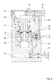
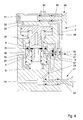
- the embodiment of the trailer brake valve according to FIGS. 3 and 4 is in wide Areas similar to the structure of the embodiment of Figs. 1 and 2, why on it can be referenced.
- the check valve 8 here has one in the direction of the axis thirteenth rectilinear valve body 9, so it is not designed as a tilt valve. Instead of Stop 15 is on the control piston 4, an inclined surface 53 is formed, with the extension 14th the check valve 8 cooperates. From the output terminal 54 leads a part the release line 48 to the release chamber 44.
- the control piston 4 is here a relay piston 55th assigned, so that the emergency brake device 3 is realized in relay design. This type is known and needs no further explanation.
- the function of this embodiment is manageable for the expert.
- a third embodiment is shown, in which the Switching the path-controlled check valve 8 causing signal also from the Displacement or stroke of the switching piston 4 is derived.
- the transmission of this signal it is done pneumatically by acting on an actuating piston 56 with compressed air, which is taken from the release line 48.
- Fig. 5 again shows the open position of the check valve 8 or the relative position of the parts at no pressure uncoupled trailer.
- Fig. 6 shows the relative position of the parts while driving.
Landscapes
- Engineering & Computer Science (AREA)
- Transportation (AREA)
- Mechanical Engineering (AREA)
- Physics & Mathematics (AREA)
- Fluid Mechanics (AREA)
- Valves And Accessory Devices For Braking Systems (AREA)
- Braking Systems And Boosters (AREA)
Applications Claiming Priority (2)
| Application Number | Priority Date | Filing Date | Title |
|---|---|---|---|
| DE10335717A DE10335717B4 (de) | 2003-08-05 | 2003-08-05 | Anhängerbremsventil für einen Kraftfahrzeug-Anhänger |
| DE10335717 | 2003-08-05 |
Publications (2)
| Publication Number | Publication Date |
|---|---|
| EP1504976A1 true EP1504976A1 (fr) | 2005-02-09 |
| EP1504976B1 EP1504976B1 (fr) | 2005-12-28 |
Family
ID=33547073
Family Applications (1)
| Application Number | Title | Priority Date | Filing Date |
|---|---|---|---|
| EP04017793A Expired - Lifetime EP1504976B1 (fr) | 2003-08-05 | 2004-07-28 | Soupape de freinage pour un remorque |
Country Status (4)
| Country | Link |
|---|---|
| EP (1) | EP1504976B1 (fr) |
| AT (1) | ATE314234T1 (fr) |
| DE (2) | DE10335717B4 (fr) |
| ES (1) | ES2253721T3 (fr) |
Cited By (5)
| Publication number | Priority date | Publication date | Assignee | Title |
|---|---|---|---|---|
| CN100439172C (zh) * | 2005-06-11 | 2008-12-03 | 淄博龙达汽车配件制造有限公司 | 双管路电控挂车制动阀 |
| EP2757010A1 (fr) * | 2013-01-18 | 2014-07-23 | Haldex Brake Products GmbH | Système de soupape pour une installation d'air comprimé d'une remorque de véhicule utilitaire |
| EP3085590A1 (fr) * | 2014-11-11 | 2016-10-26 | Studio Tecnico 6 M S.R.L. | Unite' de controle pour un système de freinage d'un remorque |
| EP3228512A1 (fr) * | 2016-04-05 | 2017-10-11 | WABCO GmbH | Clapet destiné à relâcher le frein de stationnement d'une remorque |
| DE102017011548A1 (de) | 2017-12-13 | 2019-06-13 | Wabco Gmbh | Pneumatische Ventilanordnung für Anhängerfahrzeug |
Families Citing this family (6)
| Publication number | Priority date | Publication date | Assignee | Title |
|---|---|---|---|---|
| DE102005019479B3 (de) * | 2005-04-27 | 2007-01-18 | Haldex Brake Products Gmbh | Anhängerbremsventil für einen Kraftfahrzeug-Anhänger |
| DE102013100538B4 (de) | 2013-01-18 | 2016-06-02 | Haldex Brake Products Gmbh | Druckluftanlage eines Anhängers eines Nutzfahrzeugs |
| DE102013100541A1 (de) | 2013-01-18 | 2014-07-24 | Haldex Brake Products Gmbh | Ventileinrichtung für eine Druckluftanlage eines Anhängers eines Nutzfahrzeugs |
| DE102015007383A1 (de) * | 2015-06-10 | 2016-12-15 | Wabco Gmbh | Pneumatische Bremsanlage für ein Anhängefahrzeug |
| DE102018108825B4 (de) * | 2018-04-13 | 2024-05-08 | Zf Cv Systems Hannover Gmbh | Ventilanordnung mit Notbremsventil |
| DE102018126312A1 (de) * | 2018-10-23 | 2020-04-23 | Wabco Gmbh | Elektropneumatische Bremssystemarchitektur ohne direkte pneumatische Betriebsbremsredundanz an der Hinterachse (1p1e) |
Citations (5)
| Publication number | Priority date | Publication date | Assignee | Title |
|---|---|---|---|---|
| US2772926A (en) * | 1954-08-16 | 1956-12-04 | Power Brake Equipment Company | Emergency air relay valve |
| DE2322419A1 (de) * | 1973-05-04 | 1974-11-28 | Bosch Gmbh Robert | Zweileitungs-anhaenger-steuerventil |
| GB1411981A (en) * | 1971-10-26 | 1975-10-29 | Eaton Corp | Flow control valve for a braking system |
| DE19854881A1 (de) * | 1998-04-28 | 2000-06-15 | Knorr Bremse Systeme | Park- und Rangierventil für Anhängefahrzeuge mit einer Federspeicher-Feststellbremse |
| EP1188634A2 (fr) * | 2000-09-14 | 2002-03-20 | WABCO GmbH & Co. OHG | Soupape de frein de remorque pour remorques à commande de freinage électronique et à sécurité améliorée de remorque stationnée |
Family Cites Families (1)
| Publication number | Priority date | Publication date | Assignee | Title |
|---|---|---|---|---|
| DE3144027A1 (de) * | 1981-11-05 | 1983-05-19 | Knorr-Bremse GmbH, 8000 München | "anhaenger-bremsanlage fuer kraftfahrzeuge" |
-
2003
- 2003-08-05 DE DE10335717A patent/DE10335717B4/de not_active Expired - Fee Related
-
2004
- 2004-07-28 AT AT04017793T patent/ATE314234T1/de not_active IP Right Cessation
- 2004-07-28 DE DE502004000223T patent/DE502004000223D1/de not_active Expired - Lifetime
- 2004-07-28 EP EP04017793A patent/EP1504976B1/fr not_active Expired - Lifetime
- 2004-07-28 ES ES04017793T patent/ES2253721T3/es not_active Expired - Lifetime
Patent Citations (5)
| Publication number | Priority date | Publication date | Assignee | Title |
|---|---|---|---|---|
| US2772926A (en) * | 1954-08-16 | 1956-12-04 | Power Brake Equipment Company | Emergency air relay valve |
| GB1411981A (en) * | 1971-10-26 | 1975-10-29 | Eaton Corp | Flow control valve for a braking system |
| DE2322419A1 (de) * | 1973-05-04 | 1974-11-28 | Bosch Gmbh Robert | Zweileitungs-anhaenger-steuerventil |
| DE19854881A1 (de) * | 1998-04-28 | 2000-06-15 | Knorr Bremse Systeme | Park- und Rangierventil für Anhängefahrzeuge mit einer Federspeicher-Feststellbremse |
| EP1188634A2 (fr) * | 2000-09-14 | 2002-03-20 | WABCO GmbH & Co. OHG | Soupape de frein de remorque pour remorques à commande de freinage électronique et à sécurité améliorée de remorque stationnée |
Cited By (5)
| Publication number | Priority date | Publication date | Assignee | Title |
|---|---|---|---|---|
| CN100439172C (zh) * | 2005-06-11 | 2008-12-03 | 淄博龙达汽车配件制造有限公司 | 双管路电控挂车制动阀 |
| EP2757010A1 (fr) * | 2013-01-18 | 2014-07-23 | Haldex Brake Products GmbH | Système de soupape pour une installation d'air comprimé d'une remorque de véhicule utilitaire |
| EP3085590A1 (fr) * | 2014-11-11 | 2016-10-26 | Studio Tecnico 6 M S.R.L. | Unite' de controle pour un système de freinage d'un remorque |
| EP3228512A1 (fr) * | 2016-04-05 | 2017-10-11 | WABCO GmbH | Clapet destiné à relâcher le frein de stationnement d'une remorque |
| DE102017011548A1 (de) | 2017-12-13 | 2019-06-13 | Wabco Gmbh | Pneumatische Ventilanordnung für Anhängerfahrzeug |
Also Published As
| Publication number | Publication date |
|---|---|
| DE10335717A1 (de) | 2005-03-03 |
| ATE314234T1 (de) | 2006-01-15 |
| EP1504976B1 (fr) | 2005-12-28 |
| DE502004000223D1 (de) | 2006-02-02 |
| ES2253721T3 (es) | 2006-06-01 |
| DE10335717B4 (de) | 2006-08-31 |
Similar Documents
| Publication | Publication Date | Title |
|---|---|---|
| DE102007053764B4 (de) | Bremsanlage für einen Anhänger eines Kraftfahrzeuges | |
| EP2058187B1 (fr) | Soupape de frein de stationnement pour une installation de commande pour remorques de véhicules automobiles dotées d'un frein de stationnement, frein de stationnement et ressort à air | |
| DE102010037349B4 (de) | Parkventil für einen Nutzfahrzeug-Anhänger | |
| EP2058193B1 (fr) | Soupape pouvant être entraînée manuellement pour une installation de frein d'une remorque | |
| DE102005019479B3 (de) | Anhängerbremsventil für einen Kraftfahrzeug-Anhänger | |
| EP2058188B1 (fr) | Installation de commande pour remorques de véhicules automobiles dotées d'un frein de stationnement, frein de stationnement et ressort à air | |
| DE19853718C2 (de) | Park- und Rangierventil für Anghängefahrzeuge mit einer Federspeicher-Feststellbremse | |
| EP1386810B1 (fr) | Valve combiné pour remorques avec frein de stationnement | |
| WO2018054513A1 (fr) | Arrangement de vannes de frein de stationnement pour commander un frein d'immobilisation à ressort accumulateur | |
| DE102004052375A1 (de) | System und Verfahren zur Bereitstellung trockener gefilterter Luft an einem Bremszylinder | |
| EP1504976B1 (fr) | Soupape de freinage pour un remorque | |
| DE3146366A1 (de) | Druckluftbremssystem | |
| EP3481687A1 (fr) | Soupape de relâchement de frein de stationnement pour un véhicule tracté | |
| DE102004021242B4 (de) | Luftaufbereitungsanlage und Verfahren zum Versorgen einer Nutzkraftfahrzeugbremsanlage mit Druckluft | |
| EP2463168B1 (fr) | Dispositif d'alimentation en air comprimé, procédé de commande et soupape de sécurité d'état | |
| DE2615893A1 (de) | Anhaenger-steuerventil | |
| DE2339397C3 (de) | Zweileitungs-Druckluftbremsanlage für Anhängerfahrzeuge, insbesondere Zweikreis-Bremsanlage | |
| DE1240420B (de) | Kupplung fuer Druckmittelleitungen in Bremsanlagen von Kraftfahrzeugen | |
| DE3630892C2 (fr) | ||
| DE4305679A1 (de) | Druckluftbremse für Schienenfahrzeuge | |
| DE2501070B2 (de) | Zweileitungs-druckluftbremsanlage fuer kraftfahrzeuge mit anhaenger, mit einem anhaengersteuerventil und einem sperrventil | |
| EP0842075B1 (fr) | Dispositif de commande de frein a air comprime | |
| DE1505568B1 (de) | Druckmittel-Bremsanlage fuer Anhaenger | |
| WO2018006991A1 (fr) | Soupape de relâchement de frein de stationnement pour un véhicule tracté | |
| DE1117425B (de) | Zweileitungs-Druckmittelbremsanlage fuer Wagenzuege |
Legal Events
| Date | Code | Title | Description |
|---|---|---|---|
| PUAI | Public reference made under article 153(3) epc to a published international application that has entered the european phase |
Free format text: ORIGINAL CODE: 0009012 |
|
| AK | Designated contracting states |
Kind code of ref document: A1 Designated state(s): AT BE BG CH CY CZ DE DK EE ES FI FR GB GR HU IE IT LI LU MC NL PL PT RO SE SI SK TR |
|
| AX | Request for extension of the european patent |
Extension state: AL HR LT LV MK |
|
| 17P | Request for examination filed |
Effective date: 20050226 |
|
| GRAP | Despatch of communication of intention to grant a patent |
Free format text: ORIGINAL CODE: EPIDOSNIGR1 |
|
| GRAS | Grant fee paid |
Free format text: ORIGINAL CODE: EPIDOSNIGR3 |
|
| AKX | Designation fees paid |
Designated state(s): AT BE BG CH CY CZ DE DK EE ES FI FR GB GR HU IE IT LI LU MC NL PL PT RO SE SI SK TR |
|
| GRAA | (expected) grant |
Free format text: ORIGINAL CODE: 0009210 |
|
| AK | Designated contracting states |
Kind code of ref document: B1 Designated state(s): AT BE BG CH CY CZ DE DK EE ES FI FR GB GR HU IE IT LI LU MC NL PL PT RO SE SI SK TR |
|
| PG25 | Lapsed in a contracting state [announced via postgrant information from national office to epo] |
Ref country code: NL Free format text: LAPSE BECAUSE OF FAILURE TO SUBMIT A TRANSLATION OF THE DESCRIPTION OR TO PAY THE FEE WITHIN THE PRESCRIBED TIME-LIMIT Effective date: 20051228 Ref country code: RO Free format text: LAPSE BECAUSE OF FAILURE TO SUBMIT A TRANSLATION OF THE DESCRIPTION OR TO PAY THE FEE WITHIN THE PRESCRIBED TIME-LIMIT Effective date: 20051228 Ref country code: CZ Free format text: LAPSE BECAUSE OF FAILURE TO SUBMIT A TRANSLATION OF THE DESCRIPTION OR TO PAY THE FEE WITHIN THE PRESCRIBED TIME-LIMIT Effective date: 20051228 Ref country code: FI Free format text: LAPSE BECAUSE OF FAILURE TO SUBMIT A TRANSLATION OF THE DESCRIPTION OR TO PAY THE FEE WITHIN THE PRESCRIBED TIME-LIMIT Effective date: 20051228 Ref country code: SK Free format text: LAPSE BECAUSE OF FAILURE TO SUBMIT A TRANSLATION OF THE DESCRIPTION OR TO PAY THE FEE WITHIN THE PRESCRIBED TIME-LIMIT Effective date: 20051228 Ref country code: PL Free format text: LAPSE BECAUSE OF FAILURE TO SUBMIT A TRANSLATION OF THE DESCRIPTION OR TO PAY THE FEE WITHIN THE PRESCRIBED TIME-LIMIT Effective date: 20051228 Ref country code: SI Free format text: LAPSE BECAUSE OF FAILURE TO SUBMIT A TRANSLATION OF THE DESCRIPTION OR TO PAY THE FEE WITHIN THE PRESCRIBED TIME-LIMIT Effective date: 20051228 Ref country code: IE Free format text: LAPSE BECAUSE OF FAILURE TO SUBMIT A TRANSLATION OF THE DESCRIPTION OR TO PAY THE FEE WITHIN THE PRESCRIBED TIME-LIMIT Effective date: 20051228 |
|
| REG | Reference to a national code |
Ref country code: GB Ref legal event code: FG4D Free format text: NOT ENGLISH |
|
| REG | Reference to a national code |
Ref country code: CH Ref legal event code: EP |
|
| GBT | Gb: translation of ep patent filed (gb section 77(6)(a)/1977) |
Effective date: 20051229 |
|
| REG | Reference to a national code |
Ref country code: IE Ref legal event code: FG4D Free format text: LANGUAGE OF EP DOCUMENT: GERMAN |
|
| REF | Corresponds to: |
Ref document number: 502004000223 Country of ref document: DE Date of ref document: 20060202 Kind code of ref document: P |
|
| PG25 | Lapsed in a contracting state [announced via postgrant information from national office to epo] |
Ref country code: SE Free format text: LAPSE BECAUSE OF FAILURE TO SUBMIT A TRANSLATION OF THE DESCRIPTION OR TO PAY THE FEE WITHIN THE PRESCRIBED TIME-LIMIT Effective date: 20060328 Ref country code: GR Free format text: LAPSE BECAUSE OF FAILURE TO SUBMIT A TRANSLATION OF THE DESCRIPTION OR TO PAY THE FEE WITHIN THE PRESCRIBED TIME-LIMIT Effective date: 20060328 Ref country code: DK Free format text: LAPSE BECAUSE OF FAILURE TO SUBMIT A TRANSLATION OF THE DESCRIPTION OR TO PAY THE FEE WITHIN THE PRESCRIBED TIME-LIMIT Effective date: 20060328 Ref country code: BG Free format text: LAPSE BECAUSE OF FAILURE TO SUBMIT A TRANSLATION OF THE DESCRIPTION OR TO PAY THE FEE WITHIN THE PRESCRIBED TIME-LIMIT Effective date: 20060328 |
|
| PG25 | Lapsed in a contracting state [announced via postgrant information from national office to epo] |
Ref country code: PT Free format text: LAPSE BECAUSE OF FAILURE TO SUBMIT A TRANSLATION OF THE DESCRIPTION OR TO PAY THE FEE WITHIN THE PRESCRIBED TIME-LIMIT Effective date: 20060529 |
|
| NLV1 | Nl: lapsed or annulled due to failure to fulfill the requirements of art. 29p and 29m of the patents act | ||
| REG | Reference to a national code |
Ref country code: ES Ref legal event code: FG2A Ref document number: 2253721 Country of ref document: ES Kind code of ref document: T3 |
|
| PG25 | Lapsed in a contracting state [announced via postgrant information from national office to epo] |
Ref country code: HU Free format text: LAPSE BECAUSE OF FAILURE TO SUBMIT A TRANSLATION OF THE DESCRIPTION OR TO PAY THE FEE WITHIN THE PRESCRIBED TIME-LIMIT Effective date: 20060629 |
|
| ET | Fr: translation filed | ||
| REG | Reference to a national code |
Ref country code: IE Ref legal event code: FD4D |
|
| PG25 | Lapsed in a contracting state [announced via postgrant information from national office to epo] |
Ref country code: BE Free format text: LAPSE BECAUSE OF NON-PAYMENT OF DUE FEES Effective date: 20060731 Ref country code: MC Free format text: LAPSE BECAUSE OF NON-PAYMENT OF DUE FEES Effective date: 20060731 |
|
| PLBE | No opposition filed within time limit |
Free format text: ORIGINAL CODE: 0009261 |
|
| STAA | Information on the status of an ep patent application or granted ep patent |
Free format text: STATUS: NO OPPOSITION FILED WITHIN TIME LIMIT |
|
| 26N | No opposition filed |
Effective date: 20060929 |
|
| PG25 | Lapsed in a contracting state [announced via postgrant information from national office to epo] |
Ref country code: AT Free format text: LAPSE BECAUSE OF NON-PAYMENT OF DUE FEES Effective date: 20060728 |
|
| BERE | Be: lapsed |
Owner name: HALDEX BRAKE PRODUCTS G.M.B.H. Effective date: 20060731 |
|
| PG25 | Lapsed in a contracting state [announced via postgrant information from national office to epo] |
Ref country code: EE Free format text: LAPSE BECAUSE OF FAILURE TO SUBMIT A TRANSLATION OF THE DESCRIPTION OR TO PAY THE FEE WITHIN THE PRESCRIBED TIME-LIMIT Effective date: 20051228 |
|
| PG25 | Lapsed in a contracting state [announced via postgrant information from national office to epo] |
Ref country code: TR Free format text: LAPSE BECAUSE OF FAILURE TO SUBMIT A TRANSLATION OF THE DESCRIPTION OR TO PAY THE FEE WITHIN THE PRESCRIBED TIME-LIMIT Effective date: 20051228 Ref country code: LU Free format text: LAPSE BECAUSE OF NON-PAYMENT OF DUE FEES Effective date: 20060728 |
|
| PG25 | Lapsed in a contracting state [announced via postgrant information from national office to epo] |
Ref country code: CY Free format text: LAPSE BECAUSE OF FAILURE TO SUBMIT A TRANSLATION OF THE DESCRIPTION OR TO PAY THE FEE WITHIN THE PRESCRIBED TIME-LIMIT Effective date: 20051228 |
|
| REG | Reference to a national code |
Ref country code: CH Ref legal event code: PL |
|
| PG25 | Lapsed in a contracting state [announced via postgrant information from national office to epo] |
Ref country code: LI Free format text: LAPSE BECAUSE OF NON-PAYMENT OF DUE FEES Effective date: 20080731 Ref country code: CH Free format text: LAPSE BECAUSE OF NON-PAYMENT OF DUE FEES Effective date: 20080731 |
|
| PGFP | Annual fee paid to national office [announced via postgrant information from national office to epo] |
Ref country code: ES Payment date: 20150723 Year of fee payment: 12 |
|
| PGFP | Annual fee paid to national office [announced via postgrant information from national office to epo] |
Ref country code: IT Payment date: 20150728 Year of fee payment: 12 |
|
| REG | Reference to a national code |
Ref country code: FR Ref legal event code: PLFP Year of fee payment: 13 |
|
| REG | Reference to a national code |
Ref country code: DE Ref legal event code: R082 Ref document number: 502004000223 Country of ref document: DE Representative=s name: REHBERG HUEPPE + PARTNER PATENTANWAELTE PARTG , DE Ref country code: DE Ref legal event code: R081 Ref document number: 502004000223 Country of ref document: DE Owner name: HALDEX BRAKE PRODUCTS AKTIEBOLAG, SE Free format text: FORMER OWNER: HALDEX BRAKE PRODUCTS GMBH, 69123 HEIDELBERG, DE |
|
| REG | Reference to a national code |
Ref country code: GB Ref legal event code: 732E Free format text: REGISTERED BETWEEN 20170112 AND 20170118 |
|
| REG | Reference to a national code |
Ref country code: FR Ref legal event code: TP Owner name: HALDEX BRAKE PRODUCTS AKTIEBOLAG, SE Effective date: 20170123 |
|
| REG | Reference to a national code |
Ref country code: FR Ref legal event code: PLFP Year of fee payment: 14 |
|
| PG25 | Lapsed in a contracting state [announced via postgrant information from national office to epo] |
Ref country code: IT Free format text: LAPSE BECAUSE OF NON-PAYMENT OF DUE FEES Effective date: 20160728 |
|
| PG25 | Lapsed in a contracting state [announced via postgrant information from national office to epo] |
Ref country code: ES Free format text: LAPSE BECAUSE OF NON-PAYMENT OF DUE FEES Effective date: 20160729 |
|
| REG | Reference to a national code |
Ref country code: ES Ref legal event code: FD2A Effective date: 20180627 |
|
| REG | Reference to a national code |
Ref country code: FR Ref legal event code: PLFP Year of fee payment: 15 |
|
| PGFP | Annual fee paid to national office [announced via postgrant information from national office to epo] |
Ref country code: GB Payment date: 20230724 Year of fee payment: 20 |
|
| PGFP | Annual fee paid to national office [announced via postgrant information from national office to epo] |
Ref country code: FR Payment date: 20230724 Year of fee payment: 20 Ref country code: DE Payment date: 20230525 Year of fee payment: 20 |
|
| REG | Reference to a national code |
Ref country code: DE Ref legal event code: R082 Ref document number: 502004000223 Country of ref document: DE Representative=s name: MUELLER SCHUPFNER & PARTNER PATENT- UND RECHTS, DE |
|
| REG | Reference to a national code |
Ref country code: DE Ref legal event code: R071 Ref document number: 502004000223 Country of ref document: DE |
|
| REG | Reference to a national code |
Ref country code: GB Ref legal event code: 732E Free format text: REGISTERED BETWEEN 20240704 AND 20240710 |
|
| REG | Reference to a national code |
Ref country code: GB Ref legal event code: PE20 Expiry date: 20240727 |
|
| PG25 | Lapsed in a contracting state [announced via postgrant information from national office to epo] |
Ref country code: GB Free format text: LAPSE BECAUSE OF EXPIRATION OF PROTECTION Effective date: 20240727 |
|
| PG25 | Lapsed in a contracting state [announced via postgrant information from national office to epo] |
Ref country code: GB Free format text: LAPSE BECAUSE OF EXPIRATION OF PROTECTION Effective date: 20240727 |