EP1505281A2 - Module d'admission - Google Patents
Module d'admission Download PDFInfo
- Publication number
- EP1505281A2 EP1505281A2 EP04103709A EP04103709A EP1505281A2 EP 1505281 A2 EP1505281 A2 EP 1505281A2 EP 04103709 A EP04103709 A EP 04103709A EP 04103709 A EP04103709 A EP 04103709A EP 1505281 A2 EP1505281 A2 EP 1505281A2
- Authority
- EP
- European Patent Office
- Prior art keywords
- coupling means
- suction module
- rotary shafts
- closing means
- module according
- Prior art date
- Legal status (The legal status is an assumption and is not a legal conclusion. Google has not performed a legal analysis and makes no representation as to the accuracy of the status listed.)
- Granted
Links
Images



Classifications
-
- F—MECHANICAL ENGINEERING; LIGHTING; HEATING; WEAPONS; BLASTING
- F02—COMBUSTION ENGINES; HOT-GAS OR COMBUSTION-PRODUCT ENGINE PLANTS
- F02M—SUPPLYING COMBUSTION ENGINES IN GENERAL WITH COMBUSTIBLE MIXTURES OR CONSTITUENTS THEREOF
- F02M35/00—Combustion-air cleaners, air intakes, intake silencers, or induction systems specially adapted for, or arranged on, internal-combustion engines
- F02M35/10—Air intakes; Induction systems
- F02M35/10242—Devices or means connected to or integrated into air intakes; Air intakes combined with other engine or vehicle parts
- F02M35/10255—Arrangements of valves; Multi-way valves
-
- F—MECHANICAL ENGINEERING; LIGHTING; HEATING; WEAPONS; BLASTING
- F02—COMBUSTION ENGINES; HOT-GAS OR COMBUSTION-PRODUCT ENGINE PLANTS
- F02D—CONTROLLING COMBUSTION ENGINES
- F02D11/00—Arrangements for, or adaptations to, non-automatic engine control initiation means, e.g. operator initiated
- F02D11/04—Arrangements for, or adaptations to, non-automatic engine control initiation means, e.g. operator initiated characterised by mechanical control linkages
-
- F—MECHANICAL ENGINEERING; LIGHTING; HEATING; WEAPONS; BLASTING
- F02—COMBUSTION ENGINES; HOT-GAS OR COMBUSTION-PRODUCT ENGINE PLANTS
- F02D—CONTROLLING COMBUSTION ENGINES
- F02D9/00—Controlling engines by throttling air or fuel-and-air induction conduits or exhaust conduits
- F02D9/08—Throttle valves specially adapted therefor; Arrangements of such valves in conduits
- F02D9/10—Throttle valves specially adapted therefor; Arrangements of such valves in conduits having pivotally-mounted flaps
- F02D9/1075—Materials, e.g. composites
- F02D9/108—Plastics
-
- F—MECHANICAL ENGINEERING; LIGHTING; HEATING; WEAPONS; BLASTING
- F02—COMBUSTION ENGINES; HOT-GAS OR COMBUSTION-PRODUCT ENGINE PLANTS
- F02D—CONTROLLING COMBUSTION ENGINES
- F02D9/00—Controlling engines by throttling air or fuel-and-air induction conduits or exhaust conduits
- F02D9/08—Throttle valves specially adapted therefor; Arrangements of such valves in conduits
- F02D9/10—Throttle valves specially adapted therefor; Arrangements of such valves in conduits having pivotally-mounted flaps
- F02D9/109—Throttle valves specially adapted therefor; Arrangements of such valves in conduits having pivotally-mounted flaps having two or more flaps
-
- F—MECHANICAL ENGINEERING; LIGHTING; HEATING; WEAPONS; BLASTING
- F02—COMBUSTION ENGINES; HOT-GAS OR COMBUSTION-PRODUCT ENGINE PLANTS
- F02D—CONTROLLING COMBUSTION ENGINES
- F02D9/00—Controlling engines by throttling air or fuel-and-air induction conduits or exhaust conduits
- F02D9/08—Throttle valves specially adapted therefor; Arrangements of such valves in conduits
- F02D9/10—Throttle valves specially adapted therefor; Arrangements of such valves in conduits having pivotally-mounted flaps
- F02D9/109—Throttle valves specially adapted therefor; Arrangements of such valves in conduits having pivotally-mounted flaps having two or more flaps
- F02D9/1095—Rotating on a common axis, e.g. having a common shaft
-
- F—MECHANICAL ENGINEERING; LIGHTING; HEATING; WEAPONS; BLASTING
- F02—COMBUSTION ENGINES; HOT-GAS OR COMBUSTION-PRODUCT ENGINE PLANTS
- F02M—SUPPLYING COMBUSTION ENGINES IN GENERAL WITH COMBUSTIBLE MIXTURES OR CONSTITUENTS THEREOF
- F02M35/00—Combustion-air cleaners, air intakes, intake silencers, or induction systems specially adapted for, or arranged on, internal-combustion engines
- F02M35/10—Air intakes; Induction systems
- F02M35/10091—Air intakes; Induction systems characterised by details of intake ducts: shapes; connections; arrangements
- F02M35/10124—Ducts with special cross-sections, e.g. non-circular cross-section
-
- F—MECHANICAL ENGINEERING; LIGHTING; HEATING; WEAPONS; BLASTING
- F02—COMBUSTION ENGINES; HOT-GAS OR COMBUSTION-PRODUCT ENGINE PLANTS
- F02D—CONTROLLING COMBUSTION ENGINES
- F02D9/00—Controlling engines by throttling air or fuel-and-air induction conduits or exhaust conduits
- F02D9/02—Controlling engines by throttling air or fuel-and-air induction conduits or exhaust conduits concerning induction conduits
- F02D2009/0201—Arrangements; Control features; Details thereof
- F02D2009/0279—Throttle valve control for intake system with two parallel air flow paths, each controlled by a throttle, e.g. a resilient flap disposed on a throttle
Definitions
- the invention relates to a suction module, in particular for internal combustion engine with a Intake tract with at least two intake ports and one closing means in one Intake channel for influencing the flow cross-section.
- Such a suction module is known from US 4,823,748.
- This document discloses an intake device for an internal combustion engine having at least two intake ports, wherein in each case a closing means in one of the intake ducts for influencing a Flow cross-section is provided.
- These closing means are of a common Actuating means controlled by coupling agent.
- a tolerance compensation between Actuating means and closing means are achieved via an elastic region, wherein the elasticity is generated by separate elastic components.
- the object of the invention is to provide a suction module with closing means in the intake channels of To create intake tract, which avoids the disadvantages of the prior art, in the Manufacture requires little effort and ensures reliable operation.
- the essential advantage of the invention is that the common Actuating means, which consists of two rotationally aligned with each other is connected to each other via coupling agents, wherein the coupling agent a defined angular offset between the associated with the respective coupling agent Rotary shafts generated. This means that due to the elasticity of the whole Actuating the closing of all intake ports is reliably guaranteed.
- the coupling agent is a plastic coupling, which via a each square connection is connected to a respective rotary shaft, wherein the square connection has the defined angular offset.
- the square socket offset on the plastic coupling and the outer square on a rotary shaft be arranged.
- At least one coupling means is a torsion clamp.
- This torsion clamp can consist of a spring plate and also has the angular offset.
- a further alternative embodiment provides that the rotary shafts via a lever or to couple a Federblechmitcalming.
- a lever is the Possibility to make the connection between lever and rotary shaft elastic.
- the rotary shafts can not be arranged in alignment, consists in an inventive Alternatively, the possibility of the two parallel rotating shafts over a Coupling agent to connect, which is spring-effective and a tolerance compensation causes, wherein the actuation takes place via a single rotary shaft and to be actuated Rotary shafts in each case a lever is arranged, which is in a backdrop of the spring-effective By means of moving.
- two positions are provided for the closing means, by means of the tolerance compensation can be achieved exactly. These are the Open and the closed position. Each of these positions is determined by stops.
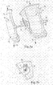
- FIG. 1a shows a flap frame 11 and a part shown further flap frame 12.
- Each flap frame has an inlet 13, 14th and an outlet 15, 16.
- Within the flap frame 11 is shown in dashed lines Flap 17 is arranged.
- the two flaps 17 and 18 have a steel square as a core. This steel square is guided to the outside and in the drawing as a shaft 19, 20 shown.
- the shaft ends are also formed as a square 21.
- To the connection the shaft 19 with the shaft 20 serves a plastic coupling shown enlarged in Fig. 1b 22, which is provided at both ends with a square opening 23, 24.
- the left and right square openings are rotated by about 1 ° to each other, around a To realize and ensure prestressing between the two flaps 17 and 18, that the flaps lie successively in the closed state.
- the preload force Can be adjusted by turning the plastic coupling and the selected material become. Especially at different temperatures affects the bias and the offset being independent of the ambient temperature effectively close the coupled flaps.
- Fig. 2a, b shows the connection of two flaps with a so-called torsion clamp. Identical parts are provided with the same reference numerals.
- the torsion clamp 25 shown as a connecting member between the two shafts 19 and 20.
- this torsion clamp consists of a thin connecting web 26 and a right side clamp member 27 and a left side Clip element 28. Both clip elements are open, i. due to the spring effect The clamp ensures a reliable hold on the corresponding shaft.
- the offset is realized by, for example 1 ° by a slight twisting of the two clip elements, resulting in a slight torsion of the connecting web can be accomplished.
- Fig. 3a, b shows a variant in which the flap 17 is entrained via a lever 29 becomes.
- the lever 29 is mounted directly on the shaft 19 and consists for example made of plastic.
- This lever is, as shown in Fig. 3b, with a spring plate 30th connected.
- This spring plate 30 is mounted on the shaft 20.
- the attachment takes place for example via a riveted joint.
- the connection of the spring plate 30 with the lever 29, for example, in that the Lever in its outer area is merely slotted and the spring plate 30 in this Slot can be inserted.
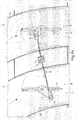
- Fig. 4 shows a solution in which two flaps 31, 32 arranged in parallel side by side are and the two intake ports 33, 42 close or release.
- a common central axis of rotation 33rd intended. This has to transmit the rotation of a square profile 34, via which extends a suspension fork 35.
- the fork 35 has at its ends so-called scenes 36, 37. In these scenes run driving pins 38, 39, respectively on a lever 40, 41 of the flaps 31, 32 are arranged.
- a turn over the central axis of rotation 33 causes the opening or closing of the flaps 31, 32nd
- Fig. 4b shows the suspension fork coupling of Fig. 4a in the closed position.
- the Biasing force which is generated via the fork 35, ensures that all flaps Both in open and closed state have the right position and become tense.
- the preload force can be adjusted via the angle of rotation of the shaft Sheet thickness and torsion length of the spring plate can be adjusted.
Landscapes
- Engineering & Computer Science (AREA)
- Chemical & Material Sciences (AREA)
- Combustion & Propulsion (AREA)
- Mechanical Engineering (AREA)
- General Engineering & Computer Science (AREA)
- Characterised By The Charging Evacuation (AREA)
- External Artificial Organs (AREA)
- Multiple-Way Valves (AREA)
Applications Claiming Priority (2)
| Application Number | Priority Date | Filing Date | Title |
|---|---|---|---|
| DE10335561A DE10335561A1 (de) | 2003-08-02 | 2003-08-02 | Saugmodul |
| DE10335561 | 2003-08-02 |
Publications (3)
| Publication Number | Publication Date |
|---|---|
| EP1505281A2 true EP1505281A2 (fr) | 2005-02-09 |
| EP1505281A3 EP1505281A3 (fr) | 2006-01-18 |
| EP1505281B1 EP1505281B1 (fr) | 2008-01-09 |
Family
ID=33547060
Family Applications (1)
| Application Number | Title | Priority Date | Filing Date |
|---|---|---|---|
| EP04103709A Expired - Lifetime EP1505281B1 (fr) | 2003-08-02 | 2004-08-02 | Module d'admission |
Country Status (3)
| Country | Link |
|---|---|
| EP (1) | EP1505281B1 (fr) |
| AT (1) | ATE383505T1 (fr) |
| DE (2) | DE10335561A1 (fr) |
Cited By (8)
| Publication number | Priority date | Publication date | Assignee | Title |
|---|---|---|---|---|
| FR2883039A1 (fr) * | 2005-03-14 | 2006-09-15 | Renault Sas | Moteur a combustion interne avec un systeme de vanne pour reguler le taux de gaz de recirculation dans le melange d'admission, et le vehicule automobile comprenant un tel moteur |
| EP1887200A1 (fr) * | 2006-08-09 | 2008-02-13 | Hamilton Sundstrand Corporation | Ensemble de soupape |
| EP1674712A3 (fr) * | 2004-12-22 | 2010-11-24 | MANN+HUMMEL GmbH | Dispositif d'admission pour un moteur à combustion interne multicylindre |
| EP2458182A1 (fr) * | 2010-11-25 | 2012-05-30 | Volkswagen AG | Dispositif destiné à influencer des débits volumiques de gaz, procédé de commande et/ou de réglage d'un flux de gaz ou d'un flux d'air de suralimentation, système d'échappement et véhicule automobile |
| EP2557298A1 (fr) * | 2011-08-12 | 2013-02-13 | Röchling Automotive AG & Co. KG | Dispositif à clapets doté d'au moins deux clapets spécialement fabriqués et montés ensemble pour un mouvement simultané |
| DE102014109754A1 (de) | 2014-07-11 | 2016-01-14 | Pierburg Gmbh | Kupplungsvorrichtung zur Verbindung zweier gegenüberliegender Wellen sowie Verfahren zur Herstellung einer derartigen Kupplungsvorrichtung |
| WO2016096838A1 (fr) * | 2014-12-19 | 2016-06-23 | Continental Automotive Gmbh | Procédé pour fabriquer un arbre pour un dispositif de soupape et dispositif de soupape ayant un arbre fabriqué selon ce procédé |
| DE102017212116A1 (de) | 2017-02-07 | 2018-08-09 | Mahle International Gmbh | Ansaugsystem für eine Brennkraftmaschine |
Families Citing this family (1)
| Publication number | Priority date | Publication date | Assignee | Title |
|---|---|---|---|---|
| DE102011102018A1 (de) * | 2011-05-19 | 2012-11-22 | Friedrich Boysen Gmbh & Co. Kg | Klappeneinrichtung |
Family Cites Families (8)
| Publication number | Priority date | Publication date | Assignee | Title |
|---|---|---|---|---|
| US2246750A (en) * | 1937-06-12 | 1941-06-24 | United Carr Fastener Corp | Coupling and coupling installation |
| FR2108817B1 (fr) * | 1970-10-08 | 1977-01-21 | Citroen Sa | |
| JPS5925048A (ja) * | 1982-08-02 | 1984-02-08 | Yamaha Motor Co Ltd | 多気筒エンジンの空気弁作動装置 |
| US4566424A (en) * | 1984-07-30 | 1986-01-28 | Outboard Marine Corporation | Flexible coupling for carburetors |
| DE3630432A1 (de) * | 1986-09-06 | 1988-03-17 | Porsche Ag | Betaetigungseinrichtung |
| US6032634A (en) * | 1994-11-02 | 2000-03-07 | Hitachi, Ltd. | Air induction system for internal-combustion engine |
| US5715782A (en) * | 1996-08-29 | 1998-02-10 | Genral Motors Corporation | Composite molded butterfly valve for an internal combustion engine |
| DE10207060B4 (de) * | 2002-02-20 | 2022-06-02 | Pierburg Gmbh | Antriebseinheit einer Stelleinheit |
-
2003
- 2003-08-02 DE DE10335561A patent/DE10335561A1/de not_active Withdrawn
-
2004
- 2004-08-02 AT AT04103709T patent/ATE383505T1/de not_active IP Right Cessation
- 2004-08-02 EP EP04103709A patent/EP1505281B1/fr not_active Expired - Lifetime
- 2004-08-02 DE DE502004005887T patent/DE502004005887D1/de not_active Expired - Lifetime
Cited By (12)
| Publication number | Priority date | Publication date | Assignee | Title |
|---|---|---|---|---|
| EP1674712A3 (fr) * | 2004-12-22 | 2010-11-24 | MANN+HUMMEL GmbH | Dispositif d'admission pour un moteur à combustion interne multicylindre |
| FR2883039A1 (fr) * | 2005-03-14 | 2006-09-15 | Renault Sas | Moteur a combustion interne avec un systeme de vanne pour reguler le taux de gaz de recirculation dans le melange d'admission, et le vehicule automobile comprenant un tel moteur |
| EP1707781A1 (fr) * | 2005-03-14 | 2006-10-04 | Renault | Moteur à combustion interne avec un système de vanne pour réguler le taux de gaz de recirculation dans le mélange d'admission, et le véhicule automobile comprenant un tel moteur. |
| EP1887200A1 (fr) * | 2006-08-09 | 2008-02-13 | Hamilton Sundstrand Corporation | Ensemble de soupape |
| US7740228B2 (en) | 2006-08-09 | 2010-06-22 | Hamilton Sundstrand Corporation | Valve assembly including a torsion spring coupling a valve shaft and actuator shaft |
| EP2458182A1 (fr) * | 2010-11-25 | 2012-05-30 | Volkswagen AG | Dispositif destiné à influencer des débits volumiques de gaz, procédé de commande et/ou de réglage d'un flux de gaz ou d'un flux d'air de suralimentation, système d'échappement et véhicule automobile |
| EP2557298A1 (fr) * | 2011-08-12 | 2013-02-13 | Röchling Automotive AG & Co. KG | Dispositif à clapets doté d'au moins deux clapets spécialement fabriqués et montés ensemble pour un mouvement simultané |
| CN103061896A (zh) * | 2011-08-12 | 2013-04-24 | 劳士领汽车股份公司及两合公司 | 具有至少两个分开制造的和为了共同运动而相互装配在一起的节气门的节气门装置 |
| DE102014109754A1 (de) | 2014-07-11 | 2016-01-14 | Pierburg Gmbh | Kupplungsvorrichtung zur Verbindung zweier gegenüberliegender Wellen sowie Verfahren zur Herstellung einer derartigen Kupplungsvorrichtung |
| DE102014109754B4 (de) * | 2014-07-11 | 2016-03-31 | Pierburg Gmbh | Kupplungsvorrichtung zur Verbindung zweier gegenüberliegender Wellen sowie Verfahren zur Herstellung einer derartigen Kupplungsvorrichtung |
| WO2016096838A1 (fr) * | 2014-12-19 | 2016-06-23 | Continental Automotive Gmbh | Procédé pour fabriquer un arbre pour un dispositif de soupape et dispositif de soupape ayant un arbre fabriqué selon ce procédé |
| DE102017212116A1 (de) | 2017-02-07 | 2018-08-09 | Mahle International Gmbh | Ansaugsystem für eine Brennkraftmaschine |
Also Published As
| Publication number | Publication date |
|---|---|
| EP1505281A3 (fr) | 2006-01-18 |
| ATE383505T1 (de) | 2008-01-15 |
| EP1505281B1 (fr) | 2008-01-09 |
| DE10335561A1 (de) | 2005-03-10 |
| DE502004005887D1 (de) | 2008-02-21 |
Similar Documents
| Publication | Publication Date | Title |
|---|---|---|
| DE102011078691A1 (de) | Luftleiteinrichtung für ein Kraftfahrzeug | |
| DE102008003177A1 (de) | Abgasrückführventil für ein Kraftfahrzeug | |
| DE102013206410A1 (de) | Luftklappenanordnung mit gesondertem Anschlagbauteil | |
| EP3138716A1 (fr) | Entrée d'air pour véhicule automobile | |
| DE112013001530T5 (de) | Koppelstange | |
| EP1505281A2 (fr) | Module d'admission | |
| EP1520738A1 (fr) | Aerateur à lamelles, en particulier pour climatisation de véhicule | |
| DE10304156A1 (de) | Gegenbahngelenk mit verbessertem Käfig | |
| DE102012020420B4 (de) | Verzweigungs- oder Zusammenführungselement für gasförmige Fluide | |
| DE60216583T2 (de) | Betätigungsvorrichtung des öffnungswinkels der lüftungsklappen von einer fahrzeugbelüftungs/- klimagruppe | |
| DE60203475T2 (de) | Drosselklappe und Drossel | |
| DE102007015166A1 (de) | Vorrichtung zur Belüftung eines Fahrzeugs | |
| DE102016219057A1 (de) | Vorrichtung zur Verstellung von Luftführungseinrichtungen und Karosseriestruktur | |
| DE102022105546A1 (de) | Luftleitvorrichtung einer Kraftfahrzeugkarosserie eines Kraftfahrzeugs | |
| DE69200907T2 (de) | Betätigungsvorrichtung für Klappen, insbesondere eines Gerätes für Heizung und/oder Klimatisierung. | |
| DE19860337A1 (de) | Vorrichtung zur Verbindung von translationsbeweglichen Elementen und Luftstrom-Steuervorrichtung mit einer solchen Verbindungsvorrichtung | |
| EP3476640A1 (fr) | Dispositif pour un pare-chocs avant d'un vehicule automobile | |
| DE102004009502B3 (de) | Klappensystem, insbesondere zur Änderung der Strömungsverhältnisse an Einlassventilen | |
| DE102009057497A1 (de) | Klappenventil zur Einleitung und Steuerung eines Frischluftstromes und eines Abgasrückführstromes | |
| DE202005011254U1 (de) | Saugmodul, insbesondere für eine Brennkraftmaschine | |
| EP1388657B1 (fr) | Ensemble de vanne | |
| DE10348839B4 (de) | Klappenanordnung | |
| EP1826040B1 (fr) | Arrangement de clapets d'air, en particulier clapets d'air extérieur et recirculé accouplés d'un véhicule | |
| DE69406870T2 (de) | Übertragungsteil mit scharnierformenden Materialbrücken | |
| DE102015208145A1 (de) | Düse für eine Spritzgießvorrichtung |
Legal Events
| Date | Code | Title | Description |
|---|---|---|---|
| PUAI | Public reference made under article 153(3) epc to a published international application that has entered the european phase |
Free format text: ORIGINAL CODE: 0009012 |
|
| AK | Designated contracting states |
Kind code of ref document: A2 Designated state(s): AT BE BG CH CY CZ DE DK EE ES FI FR GB GR HU IE IT LI LU MC NL PL PT RO SE SI SK TR |
|
| AX | Request for extension of the european patent |
Extension state: AL HR LT LV MK |
|
| RIC1 | Information provided on ipc code assigned before grant |
Ipc: 7F 02D 11/04 B Ipc: 7F 02D 9/10 A Ipc: 7F 02M 13/02 B Ipc: 7F 02M 35/10 B |
|
| PUAL | Search report despatched |
Free format text: ORIGINAL CODE: 0009013 |
|
| AK | Designated contracting states |
Kind code of ref document: A3 Designated state(s): AT BE BG CH CY CZ DE DK EE ES FI FR GB GR HU IE IT LI LU MC NL PL PT RO SE SI SK TR |
|
| AX | Request for extension of the european patent |
Extension state: AL HR LT LV MK |
|
| 17P | Request for examination filed |
Effective date: 20060203 |
|
| AKX | Designation fees paid |
Designated state(s): AT BE BG CH CY CZ DE DK EE ES FI FR GB GR HU IE IT LI LU MC NL PL PT RO SE SI SK TR |
|
| 17Q | First examination report despatched |
Effective date: 20060612 |
|
| GRAP | Despatch of communication of intention to grant a patent |
Free format text: ORIGINAL CODE: EPIDOSNIGR1 |
|
| GRAS | Grant fee paid |
Free format text: ORIGINAL CODE: EPIDOSNIGR3 |
|
| GRAA | (expected) grant |
Free format text: ORIGINAL CODE: 0009210 |
|
| AK | Designated contracting states |
Kind code of ref document: B1 Designated state(s): AT BE BG CH CY CZ DE DK EE ES FI FR GB GR HU IE IT LI LU MC NL PL PT RO SE SI SK TR |
|
| REG | Reference to a national code |
Ref country code: GB Ref legal event code: FG4D Free format text: NOT ENGLISH |
|
| REG | Reference to a national code |
Ref country code: CH Ref legal event code: EP |
|
| REG | Reference to a national code |
Ref country code: IE Ref legal event code: FG4D Free format text: LANGUAGE OF EP DOCUMENT: GERMAN |
|
| REF | Corresponds to: |
Ref document number: 502004005887 Country of ref document: DE Date of ref document: 20080221 Kind code of ref document: P |
|
| PG25 | Lapsed in a contracting state [announced via postgrant information from national office to epo] |
Ref country code: NL Free format text: LAPSE BECAUSE OF FAILURE TO SUBMIT A TRANSLATION OF THE DESCRIPTION OR TO PAY THE FEE WITHIN THE PRESCRIBED TIME-LIMIT Effective date: 20080109 Ref country code: SI Free format text: LAPSE BECAUSE OF FAILURE TO SUBMIT A TRANSLATION OF THE DESCRIPTION OR TO PAY THE FEE WITHIN THE PRESCRIBED TIME-LIMIT Effective date: 20080109 |
|
| NLV1 | Nl: lapsed or annulled due to failure to fulfill the requirements of art. 29p and 29m of the patents act | ||
| PG25 | Lapsed in a contracting state [announced via postgrant information from national office to epo] |
Ref country code: ES Free format text: LAPSE BECAUSE OF FAILURE TO SUBMIT A TRANSLATION OF THE DESCRIPTION OR TO PAY THE FEE WITHIN THE PRESCRIBED TIME-LIMIT Effective date: 20080420 Ref country code: FI Free format text: LAPSE BECAUSE OF FAILURE TO SUBMIT A TRANSLATION OF THE DESCRIPTION OR TO PAY THE FEE WITHIN THE PRESCRIBED TIME-LIMIT Effective date: 20080109 |
|
| ET | Fr: translation filed | ||
| PG25 | Lapsed in a contracting state [announced via postgrant information from national office to epo] |
Ref country code: BG Free format text: LAPSE BECAUSE OF FAILURE TO SUBMIT A TRANSLATION OF THE DESCRIPTION OR TO PAY THE FEE WITHIN THE PRESCRIBED TIME-LIMIT Effective date: 20080409 |
|
| PG25 | Lapsed in a contracting state [announced via postgrant information from national office to epo] |
Ref country code: PT Free format text: LAPSE BECAUSE OF FAILURE TO SUBMIT A TRANSLATION OF THE DESCRIPTION OR TO PAY THE FEE WITHIN THE PRESCRIBED TIME-LIMIT Effective date: 20080609 Ref country code: PL Free format text: LAPSE BECAUSE OF FAILURE TO SUBMIT A TRANSLATION OF THE DESCRIPTION OR TO PAY THE FEE WITHIN THE PRESCRIBED TIME-LIMIT Effective date: 20080109 |
|
| REG | Reference to a national code |
Ref country code: IE Ref legal event code: FD4D |
|
| PG25 | Lapsed in a contracting state [announced via postgrant information from national office to epo] |
Ref country code: SE Free format text: LAPSE BECAUSE OF FAILURE TO SUBMIT A TRANSLATION OF THE DESCRIPTION OR TO PAY THE FEE WITHIN THE PRESCRIBED TIME-LIMIT Effective date: 20080409 Ref country code: CZ Free format text: LAPSE BECAUSE OF FAILURE TO SUBMIT A TRANSLATION OF THE DESCRIPTION OR TO PAY THE FEE WITHIN THE PRESCRIBED TIME-LIMIT Effective date: 20080109 Ref country code: SK Free format text: LAPSE BECAUSE OF FAILURE TO SUBMIT A TRANSLATION OF THE DESCRIPTION OR TO PAY THE FEE WITHIN THE PRESCRIBED TIME-LIMIT Effective date: 20080109 Ref country code: DK Free format text: LAPSE BECAUSE OF FAILURE TO SUBMIT A TRANSLATION OF THE DESCRIPTION OR TO PAY THE FEE WITHIN THE PRESCRIBED TIME-LIMIT Effective date: 20080109 Ref country code: IE Free format text: LAPSE BECAUSE OF FAILURE TO SUBMIT A TRANSLATION OF THE DESCRIPTION OR TO PAY THE FEE WITHIN THE PRESCRIBED TIME-LIMIT Effective date: 20080109 |
|
| PLBE | No opposition filed within time limit |
Free format text: ORIGINAL CODE: 0009261 |
|
| STAA | Information on the status of an ep patent application or granted ep patent |
Free format text: STATUS: NO OPPOSITION FILED WITHIN TIME LIMIT |
|
| PG25 | Lapsed in a contracting state [announced via postgrant information from national office to epo] |
Ref country code: RO Free format text: LAPSE BECAUSE OF FAILURE TO SUBMIT A TRANSLATION OF THE DESCRIPTION OR TO PAY THE FEE WITHIN THE PRESCRIBED TIME-LIMIT Effective date: 20080109 |
|
| 26N | No opposition filed |
Effective date: 20081010 |
|
| PG25 | Lapsed in a contracting state [announced via postgrant information from national office to epo] |
Ref country code: MC Free format text: LAPSE BECAUSE OF NON-PAYMENT OF DUE FEES Effective date: 20080831 |
|
| REG | Reference to a national code |
Ref country code: CH Ref legal event code: PL |
|
| PG25 | Lapsed in a contracting state [announced via postgrant information from national office to epo] |
Ref country code: EE Free format text: LAPSE BECAUSE OF FAILURE TO SUBMIT A TRANSLATION OF THE DESCRIPTION OR TO PAY THE FEE WITHIN THE PRESCRIBED TIME-LIMIT Effective date: 20080109 |
|
| PG25 | Lapsed in a contracting state [announced via postgrant information from national office to epo] |
Ref country code: LI Free format text: LAPSE BECAUSE OF NON-PAYMENT OF DUE FEES Effective date: 20080831 Ref country code: CH Free format text: LAPSE BECAUSE OF NON-PAYMENT OF DUE FEES Effective date: 20080831 |
|
| PG25 | Lapsed in a contracting state [announced via postgrant information from national office to epo] |
Ref country code: BE Free format text: LAPSE BECAUSE OF NON-PAYMENT OF DUE FEES Effective date: 20080831 Ref country code: CY Free format text: LAPSE BECAUSE OF FAILURE TO SUBMIT A TRANSLATION OF THE DESCRIPTION OR TO PAY THE FEE WITHIN THE PRESCRIBED TIME-LIMIT Effective date: 20080109 |
|
| PG25 | Lapsed in a contracting state [announced via postgrant information from national office to epo] |
Ref country code: IT Free format text: LAPSE BECAUSE OF FAILURE TO SUBMIT A TRANSLATION OF THE DESCRIPTION OR TO PAY THE FEE WITHIN THE PRESCRIBED TIME-LIMIT Effective date: 20080109 |
|
| PG25 | Lapsed in a contracting state [announced via postgrant information from national office to epo] |
Ref country code: AT Free format text: LAPSE BECAUSE OF NON-PAYMENT OF DUE FEES Effective date: 20080802 |
|
| PG25 | Lapsed in a contracting state [announced via postgrant information from national office to epo] |
Ref country code: HU Free format text: LAPSE BECAUSE OF FAILURE TO SUBMIT A TRANSLATION OF THE DESCRIPTION OR TO PAY THE FEE WITHIN THE PRESCRIBED TIME-LIMIT Effective date: 20080710 Ref country code: LU Free format text: LAPSE BECAUSE OF NON-PAYMENT OF DUE FEES Effective date: 20080802 |
|
| PG25 | Lapsed in a contracting state [announced via postgrant information from national office to epo] |
Ref country code: TR Free format text: LAPSE BECAUSE OF FAILURE TO SUBMIT A TRANSLATION OF THE DESCRIPTION OR TO PAY THE FEE WITHIN THE PRESCRIBED TIME-LIMIT Effective date: 20080109 |
|
| PG25 | Lapsed in a contracting state [announced via postgrant information from national office to epo] |
Ref country code: GR Free format text: LAPSE BECAUSE OF FAILURE TO SUBMIT A TRANSLATION OF THE DESCRIPTION OR TO PAY THE FEE WITHIN THE PRESCRIBED TIME-LIMIT Effective date: 20080410 |
|
| PGFP | Annual fee paid to national office [announced via postgrant information from national office to epo] |
Ref country code: FR Payment date: 20100901 Year of fee payment: 7 |
|
| PGFP | Annual fee paid to national office [announced via postgrant information from national office to epo] |
Ref country code: GB Payment date: 20100819 Year of fee payment: 7 |
|
| GBPC | Gb: european patent ceased through non-payment of renewal fee |
Effective date: 20110802 |
|
| REG | Reference to a national code |
Ref country code: FR Ref legal event code: ST Effective date: 20120430 |
|
| PG25 | Lapsed in a contracting state [announced via postgrant information from national office to epo] |
Ref country code: FR Free format text: LAPSE BECAUSE OF NON-PAYMENT OF DUE FEES Effective date: 20110831 Ref country code: GB Free format text: LAPSE BECAUSE OF NON-PAYMENT OF DUE FEES Effective date: 20110802 |
|
| PGFP | Annual fee paid to national office [announced via postgrant information from national office to epo] |
Ref country code: DE Payment date: 20120822 Year of fee payment: 9 |
|
| PG25 | Lapsed in a contracting state [announced via postgrant information from national office to epo] |
Ref country code: DE Free format text: LAPSE BECAUSE OF NON-PAYMENT OF DUE FEES Effective date: 20140301 |
|
| REG | Reference to a national code |
Ref country code: DE Ref legal event code: R119 Ref document number: 502004005887 Country of ref document: DE Effective date: 20140301 |