EP1505309A2 - Steuerungsverfahren für eine Antriebseinheit mit automatisiertem Getriebe und eine Kupplung - Google Patents
Steuerungsverfahren für eine Antriebseinheit mit automatisiertem Getriebe und eine Kupplung Download PDFInfo
- Publication number
- EP1505309A2 EP1505309A2 EP04300466A EP04300466A EP1505309A2 EP 1505309 A2 EP1505309 A2 EP 1505309A2 EP 04300466 A EP04300466 A EP 04300466A EP 04300466 A EP04300466 A EP 04300466A EP 1505309 A2 EP1505309 A2 EP 1505309A2
- Authority
- EP
- European Patent Office
- Prior art keywords
- clutch
- torque
- engine
- control
- during
- Prior art date
- Legal status (The legal status is an assumption and is not a legal conclusion. Google has not performed a legal analysis and makes no representation as to the accuracy of the status listed.)
- Withdrawn
Links
- 230000005540 biological transmission Effects 0.000 title claims abstract description 26
- 238000000034 method Methods 0.000 title claims abstract description 26
- 238000003032 molecular docking Methods 0.000 claims abstract description 13
- 230000008859 change Effects 0.000 claims abstract description 4
- 238000005259 measurement Methods 0.000 claims description 6
- 238000005096 rolling process Methods 0.000 claims 2
- 230000001133 acceleration Effects 0.000 description 9
- 210000000056 organ Anatomy 0.000 description 6
- 238000010586 diagram Methods 0.000 description 5
- 230000002123 temporal effect Effects 0.000 description 5
- 230000004913 activation Effects 0.000 description 4
- 230000033228 biological regulation Effects 0.000 description 3
- 230000008569 process Effects 0.000 description 3
- 230000009471 action Effects 0.000 description 2
- 238000001514 detection method Methods 0.000 description 2
- 235000005911 diet Nutrition 0.000 description 2
- 230000037213 diet Effects 0.000 description 2
- 230000010354 integration Effects 0.000 description 2
- 239000003915 liquefied petroleum gas Substances 0.000 description 2
- 230000009467 reduction Effects 0.000 description 2
- 229920000297 Rayon Polymers 0.000 description 1
- 238000004026 adhesive bonding Methods 0.000 description 1
- 238000011217 control strategy Methods 0.000 description 1
- 230000036461 convulsion Effects 0.000 description 1
- 230000000881 depressing effect Effects 0.000 description 1
- 238000006073 displacement reaction Methods 0.000 description 1
- 239000012530 fluid Substances 0.000 description 1
- 238000005461 lubrication Methods 0.000 description 1
- 238000011022 operating instruction Methods 0.000 description 1
- 239000002964 rayon Substances 0.000 description 1
- 230000002787 reinforcement Effects 0.000 description 1
Images


Classifications
-
- F—MECHANICAL ENGINEERING; LIGHTING; HEATING; WEAPONS; BLASTING
- F16—ENGINEERING ELEMENTS AND UNITS; GENERAL MEASURES FOR PRODUCING AND MAINTAINING EFFECTIVE FUNCTIONING OF MACHINES OR INSTALLATIONS; THERMAL INSULATION IN GENERAL
- F16D—COUPLINGS FOR TRANSMITTING ROTATION; CLUTCHES; BRAKES
- F16D48/00—External control of clutches
- F16D48/06—Control by electric or electronic means, e.g. of fluid pressure
- F16D48/08—Regulating clutch take-up on starting
-
- B—PERFORMING OPERATIONS; TRANSPORTING
- B60—VEHICLES IN GENERAL
- B60W—CONJOINT CONTROL OF VEHICLE SUB-UNITS OF DIFFERENT TYPE OR DIFFERENT FUNCTION; CONTROL SYSTEMS SPECIALLY ADAPTED FOR HYBRID VEHICLES; ROAD VEHICLE DRIVE CONTROL SYSTEMS FOR PURPOSES NOT RELATED TO THE CONTROL OF A PARTICULAR SUB-UNIT
- B60W10/00—Conjoint control of vehicle sub-units of different type or different function
- B60W10/02—Conjoint control of vehicle sub-units of different type or different function including control of driveline clutches
-
- B—PERFORMING OPERATIONS; TRANSPORTING
- B60—VEHICLES IN GENERAL
- B60W—CONJOINT CONTROL OF VEHICLE SUB-UNITS OF DIFFERENT TYPE OR DIFFERENT FUNCTION; CONTROL SYSTEMS SPECIALLY ADAPTED FOR HYBRID VEHICLES; ROAD VEHICLE DRIVE CONTROL SYSTEMS FOR PURPOSES NOT RELATED TO THE CONTROL OF A PARTICULAR SUB-UNIT
- B60W10/00—Conjoint control of vehicle sub-units of different type or different function
- B60W10/04—Conjoint control of vehicle sub-units of different type or different function including control of propulsion units
- B60W10/06—Conjoint control of vehicle sub-units of different type or different function including control of propulsion units including control of combustion engines
-
- B—PERFORMING OPERATIONS; TRANSPORTING
- B60—VEHICLES IN GENERAL
- B60W—CONJOINT CONTROL OF VEHICLE SUB-UNITS OF DIFFERENT TYPE OR DIFFERENT FUNCTION; CONTROL SYSTEMS SPECIALLY ADAPTED FOR HYBRID VEHICLES; ROAD VEHICLE DRIVE CONTROL SYSTEMS FOR PURPOSES NOT RELATED TO THE CONTROL OF A PARTICULAR SUB-UNIT
- B60W30/00—Purposes of road vehicle drive control systems not related to the control of a particular sub-unit, e.g. of systems using conjoint control of vehicle sub-units
- B60W30/18—Propelling the vehicle
- B60W30/18009—Propelling the vehicle related to particular drive situations
- B60W30/18027—Drive off, accelerating from standstill
-
- B—PERFORMING OPERATIONS; TRANSPORTING
- B60—VEHICLES IN GENERAL
- B60W—CONJOINT CONTROL OF VEHICLE SUB-UNITS OF DIFFERENT TYPE OR DIFFERENT FUNCTION; CONTROL SYSTEMS SPECIALLY ADAPTED FOR HYBRID VEHICLES; ROAD VEHICLE DRIVE CONTROL SYSTEMS FOR PURPOSES NOT RELATED TO THE CONTROL OF A PARTICULAR SUB-UNIT
- B60W2510/00—Input parameters relating to a particular sub-units
- B60W2510/06—Combustion engines, Gas turbines
- B60W2510/0695—Inertia
-
- B—PERFORMING OPERATIONS; TRANSPORTING
- B60—VEHICLES IN GENERAL
- B60W—CONJOINT CONTROL OF VEHICLE SUB-UNITS OF DIFFERENT TYPE OR DIFFERENT FUNCTION; CONTROL SYSTEMS SPECIALLY ADAPTED FOR HYBRID VEHICLES; ROAD VEHICLE DRIVE CONTROL SYSTEMS FOR PURPOSES NOT RELATED TO THE CONTROL OF A PARTICULAR SUB-UNIT
- B60W2530/00—Input parameters relating to vehicle conditions or values, not covered by groups B60W2510/00 or B60W2520/00
- B60W2530/10—Weight
-
- B—PERFORMING OPERATIONS; TRANSPORTING
- B60—VEHICLES IN GENERAL
- B60W—CONJOINT CONTROL OF VEHICLE SUB-UNITS OF DIFFERENT TYPE OR DIFFERENT FUNCTION; CONTROL SYSTEMS SPECIALLY ADAPTED FOR HYBRID VEHICLES; ROAD VEHICLE DRIVE CONTROL SYSTEMS FOR PURPOSES NOT RELATED TO THE CONTROL OF A PARTICULAR SUB-UNIT
- B60W2530/00—Input parameters relating to vehicle conditions or values, not covered by groups B60W2510/00 or B60W2520/00
- B60W2530/20—Tyre data
-
- B—PERFORMING OPERATIONS; TRANSPORTING
- B60—VEHICLES IN GENERAL
- B60W—CONJOINT CONTROL OF VEHICLE SUB-UNITS OF DIFFERENT TYPE OR DIFFERENT FUNCTION; CONTROL SYSTEMS SPECIALLY ADAPTED FOR HYBRID VEHICLES; ROAD VEHICLE DRIVE CONTROL SYSTEMS FOR PURPOSES NOT RELATED TO THE CONTROL OF A PARTICULAR SUB-UNIT
- B60W2540/00—Input parameters relating to occupants
- B60W2540/10—Accelerator pedal position
-
- B—PERFORMING OPERATIONS; TRANSPORTING
- B60—VEHICLES IN GENERAL
- B60W—CONJOINT CONTROL OF VEHICLE SUB-UNITS OF DIFFERENT TYPE OR DIFFERENT FUNCTION; CONTROL SYSTEMS SPECIALLY ADAPTED FOR HYBRID VEHICLES; ROAD VEHICLE DRIVE CONTROL SYSTEMS FOR PURPOSES NOT RELATED TO THE CONTROL OF A PARTICULAR SUB-UNIT
- B60W2710/00—Output or target parameters relating to a particular sub-units
- B60W2710/02—Clutches
- B60W2710/027—Clutch torque
-
- F—MECHANICAL ENGINEERING; LIGHTING; HEATING; WEAPONS; BLASTING
- F16—ENGINEERING ELEMENTS AND UNITS; GENERAL MEASURES FOR PRODUCING AND MAINTAINING EFFECTIVE FUNCTIONING OF MACHINES OR INSTALLATIONS; THERMAL INSULATION IN GENERAL
- F16D—COUPLINGS FOR TRANSMITTING ROTATION; CLUTCHES; BRAKES
- F16D2500/00—External control of clutches by electric or electronic means
- F16D2500/10—System to be controlled
- F16D2500/104—Clutch
- F16D2500/10406—Clutch position
- F16D2500/10412—Transmission line of a vehicle
-
- F—MECHANICAL ENGINEERING; LIGHTING; HEATING; WEAPONS; BLASTING
- F16—ENGINEERING ELEMENTS AND UNITS; GENERAL MEASURES FOR PRODUCING AND MAINTAINING EFFECTIVE FUNCTIONING OF MACHINES OR INSTALLATIONS; THERMAL INSULATION IN GENERAL
- F16D—COUPLINGS FOR TRANSMITTING ROTATION; CLUTCHES; BRAKES
- F16D2500/00—External control of clutches by electric or electronic means
- F16D2500/10—System to be controlled
- F16D2500/104—Clutch
- F16D2500/10443—Clutch type
- F16D2500/1045—Friction clutch
-
- F—MECHANICAL ENGINEERING; LIGHTING; HEATING; WEAPONS; BLASTING
- F16—ENGINEERING ELEMENTS AND UNITS; GENERAL MEASURES FOR PRODUCING AND MAINTAINING EFFECTIVE FUNCTIONING OF MACHINES OR INSTALLATIONS; THERMAL INSULATION IN GENERAL
- F16D—COUPLINGS FOR TRANSMITTING ROTATION; CLUTCHES; BRAKES
- F16D2500/00—External control of clutches by electric or electronic means
- F16D2500/30—Signal inputs
- F16D2500/308—Signal inputs from the transmission
- F16D2500/30806—Engaged transmission ratio
-
- F—MECHANICAL ENGINEERING; LIGHTING; HEATING; WEAPONS; BLASTING
- F16—ENGINEERING ELEMENTS AND UNITS; GENERAL MEASURES FOR PRODUCING AND MAINTAINING EFFECTIVE FUNCTIONING OF MACHINES OR INSTALLATIONS; THERMAL INSULATION IN GENERAL
- F16D—COUPLINGS FOR TRANSMITTING ROTATION; CLUTCHES; BRAKES
- F16D2500/00—External control of clutches by electric or electronic means
- F16D2500/30—Signal inputs
- F16D2500/31—Signal inputs from the vehicle
- F16D2500/3107—Vehicle weight
-
- F—MECHANICAL ENGINEERING; LIGHTING; HEATING; WEAPONS; BLASTING
- F16—ENGINEERING ELEMENTS AND UNITS; GENERAL MEASURES FOR PRODUCING AND MAINTAINING EFFECTIVE FUNCTIONING OF MACHINES OR INSTALLATIONS; THERMAL INSULATION IN GENERAL
- F16D—COUPLINGS FOR TRANSMITTING ROTATION; CLUTCHES; BRAKES
- F16D2500/00—External control of clutches by electric or electronic means
- F16D2500/30—Signal inputs
- F16D2500/314—Signal inputs from the user
- F16D2500/31406—Signal inputs from the user input from pedals
- F16D2500/31413—Clutch pedal position
-
- F—MECHANICAL ENGINEERING; LIGHTING; HEATING; WEAPONS; BLASTING
- F16—ENGINEERING ELEMENTS AND UNITS; GENERAL MEASURES FOR PRODUCING AND MAINTAINING EFFECTIVE FUNCTIONING OF MACHINES OR INSTALLATIONS; THERMAL INSULATION IN GENERAL
- F16D—COUPLINGS FOR TRANSMITTING ROTATION; CLUTCHES; BRAKES
- F16D2500/00—External control of clutches by electric or electronic means
- F16D2500/30—Signal inputs
- F16D2500/314—Signal inputs from the user
- F16D2500/31406—Signal inputs from the user input from pedals
- F16D2500/3144—Accelerator pedal position
-
- F—MECHANICAL ENGINEERING; LIGHTING; HEATING; WEAPONS; BLASTING
- F16—ENGINEERING ELEMENTS AND UNITS; GENERAL MEASURES FOR PRODUCING AND MAINTAINING EFFECTIVE FUNCTIONING OF MACHINES OR INSTALLATIONS; THERMAL INSULATION IN GENERAL
- F16D—COUPLINGS FOR TRANSMITTING ROTATION; CLUTCHES; BRAKES
- F16D2500/00—External control of clutches by electric or electronic means
- F16D2500/50—Problem to be solved by the control system
- F16D2500/506—Relating the transmission
- F16D2500/50684—Torque resume after shifting
Definitions
- the present invention relates to the control of the group GMP powertrain of a vehicle equipped with a transmission automated clutch TA_E.
- the clutch can be of the type dry or wet. It mainly applies during the phase slip cancellation that precedes the final tightening of the clutch.
- This type of automated transmission is distinguished by a component for transmitting the motor torque in the modulating the absence of transmitted torque up to a couple normally at least equal to the maximum torque of the engine drive, for example thermal: the clutch.
- This kind of transmission therefore excludes torque converters, which are able to amplify the motor torque when the speed of the converter turbine is above a mode threshold amplifier.
- a clutch is called dry when the transmission torque is achieved by friction or gluing of two pieces that are in an oil-free casing and that slide one with respect to the other or stick in the absence of oil or other fluid, There may have one or more dry clutches.
- a vehicle in manual gearbox has a dry clutch in the clutch bell, between the engine and the gearbox BV.
- a clutch is called wet when the friction of parts is made with the contribution of any lubrication to let the surfaces slide during the opening phase and to cool the surfaces.
- this invention can be used, for example, in the following organs: a Robotic Gearbox, a Clutch driven, a transmission with two clutches in Parallel type "Twin Clutch", a transmission continuously Variable CVT, Automatic Gearbox BVA without converter, a gearbox with electric machine integrated, an electric gearbox of the kind Clutch by wire, ...
- the present invention applies the control of any body that has to modulate the couple in order to take off a vehicle without the driver intervening (except in clutch by wire, where the pedal clutch is electric).
- This torque can come from an engine gasoline, diesel, liquefied petroleum gas LPG, or machine electric, or a combination of these types of motor as in the case of a hybrid vehicle.
- this function can be used for all Vehicle types using Automated Transmission to Clutch TA_E.
- This invention can be applied in the case of take off, but also in the case of a gear change.
- This invention can be applied in the case where a computer controls the torque transmitted by the clutch only, or in the case where a calculator controls the torque transmitted and the requested torque to the engine, or finally in the case where a computer only controls the torque requested from the engine thermal.
- the teaching of the state of the art therefore consists of a strategy proposing a berthing with a revs constant, while the primary regime tends to increase or decrease when changing gear or take off.
- the cancellation of the slip is therefore between two organs not having the same dynamics. So we are forced to do move the primary regime towards the engine speed and finally does not maintain the desired dynamics for the vehicle.
- the invention proposes to extend the use of engine torque alone in the case of a type clutch "Clutch by wire” and simultaneous control of transmitted couples and engine for all other automated transmissions to clutch TA_E, like the Robotic gear box.
- the method of the invention is based on the observation that the phase berth presented in the state of the art does not allow to ensure the comfort of passengers while respecting the will of the driver in terms of acceleration or deceleration.
- the fact not to respect the dynamics desired by the driver is besides, a source of discomfort. This finding is particularly true when the vehicle takes off.
- the method of the invention consists in imposing that the two rotating members have the same dynamics, so that one of the organs does not come braking the other when closing the clutch.
- N word N prim + N word, pred , expression in which N word, pred is a constant of integration which is determined based on the measurement of the degree of depression of the accelerator pedal.
- FIG. 1 represents a kinematic chain allowing an implementation of the invention.
- Engine 1 has a shaft output 6 which is mechanically connected to the input shaft a clutch 2 whose output shaft of 5 is connected to the input of the transmission 7.
- An output shaft 8 of the transmission 7 is connected via a differential 9 to the drive wheels of the vehicle.
- Non-actuators represent the point of operation engine under the control of a calculator 11 including another channel is connected to a control interface of an actuator 10 to control the opening, sliding and contact of the clutch 2.
- Sensors are arranged on the transmission of how to determine the different operating parameters of the vehicle as the primary speed of speed on the shaft 5.
- Figure 2 shows a device diagram making appear the actuators as well as the sensors.
- This invention is implemented in the calculator and forms part of the strategy forming the law of management of the takeoff or the passage of speed.
- This embodiment of the invention is placed in the framework of a multivariable command.
- An example of realization such a multivariable control is described in particular in the French patent application FR-A-2,796,894 filed in the name of same applicant. It is expressly referred to and a such a command will not be more described.
- the enslavement of motor is executed by a block 15, and the control of the clutch is executed by a block 16.
- These two checks are carried out on the basis of the law of management of the takeoff or the passage of speed, executed by a block 14.
- the control of the motor 15 receives from the takeoff management block 14, a torque setpoint motor and the control of the clutch 16 receives a set of torque transmitted from the take-off management block 14.
- the servocontrol of the motor 1 executed by the block 15, produces activation control of the actuator layer 17 so as to determine the operating point of the motor 1, that is, setting the engine speed and torque engine.
- the control of the clutch 2 is executed by block 16 and produces activation control of the actuator layer 17 in order to determine a plateau berthing regime and the clutch lining 2.
- Sensors 18 produce measurements or estimates to characterize at every moment the engine 1 operating parameters: engine speed instant N_mot_mes and if necessary, motor torque snapshot C_mot_mes. These various parameters are transmitted including take-off management block 14 and the block of servo control 15.
- Sensors 19 produce measurements or estimates to characterize at every moment the operating parameters clutch 2: Primary Regine N_prim_mes. These various parameters are transmitted in particular to takeoff management block 14 as well as the control block of enslavement 16.
- C sensors produce measurements or estimates to characterize every moment or during initialization of the method of the invention the operating parameters of the vehicle: radius of the drive wheels of the vehicle, mass of the vehicle, speed of movement of the vehicle, total transmission. These various parameters are transmitted to the three blocks 14 berthing management, 15 control of the servo of the engine and 16 of the control of the clutch.
- the berthing management block 14 also receives as input the instantaneous value of the degree of depression of the pedal acceleration, ⁇ _ped, in particular to determine a point engine operating instruction, including in particular the engine speed and torque transmitted.
- FIG. 3 is a flowchart describing the different control steps in the case of a take-off.
- the process of the invention concerns the beginning of step E4: "Cancel the slip and close the clutch ", ie the cancellation of the slip, or docking regime.
- Each of the lines perpendicular to the arrow indicating the control path indicates the logical state of the referenced test to go to the next step and the different tests allow to test the state of reinforcement of the pedal throttle, the opening condition of the clutch, the detection of the licking point, the detection of the slip state on the platter and clutch stopper.
- the nine successive tests are indicated by references d1 to d9.
- step E1 which makes it possible to control the idling of the drive motor
- step E2 which allows to bring the clutch at the point of licking thanks to a linear displacement of the clutch thrust actuated by an actuator linear controlled in position and speed.
- step E4 directly concerned by the invention of cancellation of the sliding (docking) and closing the clutch 2. If the d8 test is not true here is the test d9 is wrong, we go back to a step E6 opening of the clutch 2.
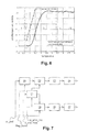
- FIG 7 there is shown a particular mode of performing the method of the invention when it is executed on a particular on-board computer.
- the parameters necessary for the operation of instructions of the invention are transmitted and in particular successively the values of ⁇ _ped of degree of accelerator pedal depression, Reg_Decol which indicates the end of the regulation of takeoff of the stage of takeoff 5 ( Figure 3), and the instantaneous measurement values of engine speed N_mot_mes and from the primary mode to the output clutch N_prim_mes.
- a first block of a treatment 20 receives on a first input the degree depressing the accelerator pedal and on a second entry the indicator of end of regulation status of the lift-off.
- the processing block 20 produces at its output a value indicator of a motor speed which, in a particular mode of realization, is calculated from the position of the pedal, its temporal variation or from the measured value of the engine.
- the measured value of the engine speed N_mot_mes is transmitted to a first input of a processing block 21 whose a second input receives the measured value of the primary regime N_prim_mes which is also transmitted to a first entry of a adder 25 as will be described later.
- the block of processing 21 applies the saved strategy in the calculator implementing the method of the invention and makes it possible to improve the comfort of the people transported in the vehicle during docking.
- the strategy helps to balance the dynamics or the dynamic states of the clutch and the motor by applying for example as described above the equality of temporal variations at engine speed and primary regime.
- Processing block 21 produces on a first output a engine speed control increment which is transmitted to a second input of the adder 22.
- the new indicative signal 5 the engine speed setpoint is transmitted to an input of one processing block 23 which realizes the control of the motor and an output terminal that transmits a control signal servocontrol to the activation input of an actuator 24.
- the actuator 24 applies a mechanical action on the organs suitable engine as the throttle.
- Processing block 21 produces on a second output a primary rate control increment that is passed to a second input of the adder 25.
- the new signal indicative of the setpoint of the position of the clutch thrust bearing is transmitted to an input of a block of a processing 26 which realizes the steering the clutch is an output terminal that transmits a pilot signal to an activation input terminal of a actuator 27.
- the actuator 27 applies a mechanical action on the stop of the clutch so as to regulate the transmitted torque.
- Figures 4, 5 and 6 correspond to a take-off.
- the numbers indicated correspond to the six phases of the flowchart of Figure 3.
- Figure 4 shows the temporal evolution of diets Nmot_mes engine and primary Nprim_mes during a takeoff.
- the figure 5 presents the temporal evolution of the motor couples Cmot_mes and transmitted Ctrans_mes during a take-off.
- the figure 6 presents the temporal evolution of the acceleration of the vehicle during take off.
Landscapes
- Engineering & Computer Science (AREA)
- Mechanical Engineering (AREA)
- Chemical & Material Sciences (AREA)
- Combustion & Propulsion (AREA)
- Transportation (AREA)
- General Engineering & Computer Science (AREA)
- Automation & Control Theory (AREA)
- Physics & Mathematics (AREA)
- Fluid Mechanics (AREA)
- Hydraulic Clutches, Magnetic Clutches, Fluid Clutches, And Fluid Joints (AREA)
Applications Claiming Priority (2)
| Application Number | Priority Date | Filing Date | Title |
|---|---|---|---|
| FR0309775 | 2003-08-08 | ||
| FR0309775A FR2858586B1 (fr) | 2003-08-08 | 2003-08-08 | Procede de controle d'un groupe motopropulseur equipe d'une transmission automatisee a embrayage |
Publications (2)
| Publication Number | Publication Date |
|---|---|
| EP1505309A2 true EP1505309A2 (de) | 2005-02-09 |
| EP1505309A3 EP1505309A3 (de) | 2008-01-23 |
Family
ID=33548323
Family Applications (1)
| Application Number | Title | Priority Date | Filing Date |
|---|---|---|---|
| EP04300466A Withdrawn EP1505309A3 (de) | 2003-08-08 | 2004-07-23 | Steuerungsverfahren für eine Antriebseinheit mit automatisiertem Getriebe und eine Kupplung |
Country Status (2)
| Country | Link |
|---|---|
| EP (1) | EP1505309A3 (de) |
| FR (1) | FR2858586B1 (de) |
Cited By (6)
| Publication number | Priority date | Publication date | Assignee | Title |
|---|---|---|---|---|
| WO2009083325A1 (de) * | 2007-12-27 | 2009-07-09 | Robert Bosch Gmbh | Verfahren zum betreiben einer hybridantriebsvorrichtung |
| WO2012171521A1 (de) * | 2011-06-16 | 2012-12-20 | Schaeffler Technologies AG & Co. KG | Verfahren zur steuerung einer automatisierten reibungskupplung in einem antriebsstrang eines kraftfahrzeugs während eines anfahrvorgangs |
| WO2014155010A1 (fr) * | 2013-03-29 | 2014-10-02 | Renault S.A.S | Procede et dispositif de controle du redemarrage d'un vehicule equipe d'une transmission automatisee |
| EP2913504A4 (de) * | 2012-10-25 | 2016-04-20 | Aisin Seiki | Antriebsvorrichtung für ein fahrzeug |
| FR3066167A1 (fr) * | 2017-05-09 | 2018-11-16 | Peugeot Citroen Automobiles Sa | Procede de controle d'un groupe motopropulseur d'un vehicule hybride pour le demarrage de ce vehicule |
| CN113593354A (zh) * | 2021-07-30 | 2021-11-02 | 吉林大学 | 一种无变速器电动教练车离合器操控模拟装置 |
Families Citing this family (1)
| Publication number | Priority date | Publication date | Assignee | Title |
|---|---|---|---|---|
| FR2919697B1 (fr) * | 2007-07-31 | 2009-12-11 | Peugeot Citroen Automobiles Sa | Procede de commande d'un groupe moto propulseur de vehicule. |
Citations (4)
| Publication number | Priority date | Publication date | Assignee | Title |
|---|---|---|---|---|
| EP0707998A2 (de) | 1994-10-21 | 1996-04-24 | Toyota Jidosha Kabushiki Kaisha | Vorrichtung zum Steuern des Schlupfes einer Kraftfahrzeugkupplung während des Anfahrens |
| FR2796894A1 (fr) | 1999-07-27 | 2001-02-02 | Renault | Dispositif de commande du demarrage d'un vehicule automobile |
| DE10030837A1 (de) | 1999-06-30 | 2001-02-22 | Luk Lamellen & Kupplungsbau | Kraftfahrzeug |
| EP1258368A2 (de) | 2001-05-17 | 2002-11-20 | Canon Kabushiki Kaisha | Druckgerät und Drucksteuerungsverfahren |
Family Cites Families (4)
| Publication number | Priority date | Publication date | Assignee | Title |
|---|---|---|---|---|
| JP3572623B2 (ja) * | 1992-08-31 | 2004-10-06 | 本田技研工業株式会社 | 車両用クラッチの制御装置 |
| ITBO20000627A1 (it) * | 2000-10-27 | 2002-04-27 | Magneti Marelli Spa | Metodo per l'esecuzione del disinnesto marcia in un cambio manuale servocomandato |
| DE10124656A1 (de) * | 2001-05-18 | 2002-11-21 | Zf Sachs Ag | Verfahren zur Durchführung eines Anfahrvorgangs bei einem Antriebssystem |
| WO2003016742A1 (de) * | 2001-08-16 | 2003-02-27 | Luk Lamellen Und Kupplungsbau Beteiligungs Kg | Verfahren zur schlupfsteuerung einer kupplung |
-
2003
- 2003-08-08 FR FR0309775A patent/FR2858586B1/fr not_active Expired - Fee Related
-
2004
- 2004-07-23 EP EP04300466A patent/EP1505309A3/de not_active Withdrawn
Patent Citations (4)
| Publication number | Priority date | Publication date | Assignee | Title |
|---|---|---|---|---|
| EP0707998A2 (de) | 1994-10-21 | 1996-04-24 | Toyota Jidosha Kabushiki Kaisha | Vorrichtung zum Steuern des Schlupfes einer Kraftfahrzeugkupplung während des Anfahrens |
| DE10030837A1 (de) | 1999-06-30 | 2001-02-22 | Luk Lamellen & Kupplungsbau | Kraftfahrzeug |
| FR2796894A1 (fr) | 1999-07-27 | 2001-02-02 | Renault | Dispositif de commande du demarrage d'un vehicule automobile |
| EP1258368A2 (de) | 2001-05-17 | 2002-11-20 | Canon Kabushiki Kaisha | Druckgerät und Drucksteuerungsverfahren |
Cited By (10)
| Publication number | Priority date | Publication date | Assignee | Title |
|---|---|---|---|---|
| WO2009083325A1 (de) * | 2007-12-27 | 2009-07-09 | Robert Bosch Gmbh | Verfahren zum betreiben einer hybridantriebsvorrichtung |
| US9180768B2 (en) | 2007-12-27 | 2015-11-10 | Robert Bosch Gmbh | Method for operating a hybrid drive device |
| WO2012171521A1 (de) * | 2011-06-16 | 2012-12-20 | Schaeffler Technologies AG & Co. KG | Verfahren zur steuerung einer automatisierten reibungskupplung in einem antriebsstrang eines kraftfahrzeugs während eines anfahrvorgangs |
| KR20140031312A (ko) * | 2011-06-16 | 2014-03-12 | 섀플러 테크놀로지스 아게 운트 코. 카게 | 스타팅 절차 동안 자동차의 구동 트레인에서 자동식 마찰 클러치를 제어하는 방법 |
| EP2913504A4 (de) * | 2012-10-25 | 2016-04-20 | Aisin Seiki | Antriebsvorrichtung für ein fahrzeug |
| WO2014155010A1 (fr) * | 2013-03-29 | 2014-10-02 | Renault S.A.S | Procede et dispositif de controle du redemarrage d'un vehicule equipe d'une transmission automatisee |
| FR3003833A1 (fr) * | 2013-03-29 | 2014-10-03 | Renault Sa | Procede et dispositif de controle du redemarrage d'un vehicule equipe d'une transmission automatique |
| US9533686B2 (en) | 2013-03-29 | 2017-01-03 | Renault S.A.S. | Method and device for controlling the restarting of a vehicle provided with an automatic transmission |
| FR3066167A1 (fr) * | 2017-05-09 | 2018-11-16 | Peugeot Citroen Automobiles Sa | Procede de controle d'un groupe motopropulseur d'un vehicule hybride pour le demarrage de ce vehicule |
| CN113593354A (zh) * | 2021-07-30 | 2021-11-02 | 吉林大学 | 一种无变速器电动教练车离合器操控模拟装置 |
Also Published As
| Publication number | Publication date |
|---|---|
| FR2858586B1 (fr) | 2006-03-03 |
| FR2858586A1 (fr) | 2005-02-11 |
| EP1505309A3 (de) | 2008-01-23 |
Similar Documents
| Publication | Publication Date | Title |
|---|---|---|
| EP2176951B1 (de) | Fahrzeugunterstützungsvorrichtung | |
| EP1563207B1 (de) | Auswahlverfahren für die übersetzung eines automatischen getriebes | |
| FR2935660A1 (fr) | Procede et dispositif de compensation de rupture du couple fourni par le groupe motopropulseur d'un vehicule hybride au cours d'un changement de vitesse | |
| FR2803359A1 (fr) | Procede pour determiner le rapport de transmission d'une boite de vitesses automatique installee dans la ligne de transmission d'un vehicule automobile | |
| EP1505309A2 (de) | Steuerungsverfahren für eine Antriebseinheit mit automatisiertem Getriebe und eine Kupplung | |
| EP2556276B1 (de) | Verfahren und vorrichtung zur einstellung der betätigerkraft der gangschaltung bei einem halbautomatikgetriebe | |
| EP2141379B1 (de) | Verfahren zum Kontrollieren der Schließphasen einer Kupplung eines robotergesteuerten Übersetzungssystems eines Autos | |
| WO2020053505A1 (fr) | Procede de commande de couple moteur d'un groupe motopropulseur permettant de desactiver la compensation de couple inertiel | |
| EP2297476B1 (de) | Modul zur drehmomentsteuerung einer reibkupplungsvorrichtung eines kraftfahrzeugantriebsstrangs mit zustandsbeobachter | |
| FR2859258A1 (fr) | Procede pour selectioner une loi de commande du systeme de pilotage d'un embrayage en determinant trois points de fonctionnement | |
| FR2976036A1 (fr) | Procede d'apprentissage du point de lechage d'un embrayage d'une boite a double embrayage avec detection des jeux de boite de vitesses | |
| CN110030378B (zh) | 确定手动变速器中的啮合挡位的方法 | |
| EP1846647B1 (de) | Verfahren zur steuerung der leistungsumkehr in einem system mit einem drehmomentwandler und mechanische einheit, die das verfahren umfasst | |
| WO2018087438A1 (fr) | Dispositif et procédé de pilotage d'une boite de vitesses robotisee pour vehicule automobile a propulsion hybride | |
| EP2616717A1 (de) | Verfahren zur aufwärtsschaltung für ein automatikgetriebe eines kraftfahrzeuges | |
| FR2920501A1 (fr) | Procede et systeme de pilotage d'un organe de couplage d'une chaine de traction d'un vehicule automobile | |
| EP1429011A1 (de) | Verfahren und System zur Steuerung des Drehmoments eines Verbrennungsmotors für ein Automobil | |
| EP2168833A1 (de) | Method and device for protecting an element for transmitting engine torque to the wheels of an automobile | |
| FR2899282A1 (fr) | Systeme de controle de fonctionnement d'un groupe moto- propulseur de vehicule automobile pour l'attenuation de perturbations lors du passage de jeu d'une transmission du vehicule. | |
| FR3103440A1 (fr) | Procede de determination du couple transmis par le moteur a la chaine de traction | |
| EP3625472B1 (de) | Verfahren zur steuerung eines antriebsstrangs zur thermischen regelung eines hydraulikkreises | |
| FR3157318A1 (fr) | Système et procédé de commande d’un système de propulsion d’un véhicule hybride | |
| EP2529129B1 (de) | Verfahren für die steuerung eines motors und einer elektronischen kupplung während der ersten phase des getriebeübersetzungswechsels bei einem mechanischen getriebekasten | |
| FR3106320A1 (fr) | Procédé de commande d’un véhicule automobile pour éviter les à coups à l’embrayage | |
| WO2006027527A1 (fr) | Procede de commande d'un systeme de transmission de couple de vehicule automobile et systeme de commande correspondant |
Legal Events
| Date | Code | Title | Description |
|---|---|---|---|
| PUAI | Public reference made under article 153(3) epc to a published international application that has entered the european phase |
Free format text: ORIGINAL CODE: 0009012 |
|
| AK | Designated contracting states |
Kind code of ref document: A2 Designated state(s): AT BE BG CH CY CZ DE DK EE ES FI FR GB GR HU IE IT LI LU MC NL PL PT RO SE SI SK TR |
|
| AX | Request for extension of the european patent |
Extension state: AL HR LT LV MK |
|
| PUAL | Search report despatched |
Free format text: ORIGINAL CODE: 0009013 |
|
| AK | Designated contracting states |
Kind code of ref document: A3 Designated state(s): AT BE BG CH CY CZ DE DK EE ES FI FR GB GR HU IE IT LI LU MC NL PL PT RO SE SI SK TR |
|
| AX | Request for extension of the european patent |
Extension state: AL HR LT LV MK |
|
| 17P | Request for examination filed |
Effective date: 20080711 |
|
| AKX | Designation fees paid |
Designated state(s): AT BE BG CH CY CZ DE DK EE ES FI FR GB GR HU IE IT LI LU MC NL PL PT RO SE SI SK TR |
|
| 17Q | First examination report despatched |
Effective date: 20090717 |
|
| STAA | Information on the status of an ep patent application or granted ep patent |
Free format text: STATUS: THE APPLICATION IS DEEMED TO BE WITHDRAWN |
|
| 18D | Application deemed to be withdrawn |
Effective date: 20130724 |