EP3625472B1 - Verfahren zur steuerung eines antriebsstrangs zur thermischen regelung eines hydraulikkreises - Google Patents
Verfahren zur steuerung eines antriebsstrangs zur thermischen regelung eines hydraulikkreises Download PDFInfo
- Publication number
- EP3625472B1 EP3625472B1 EP18719979.9A EP18719979A EP3625472B1 EP 3625472 B1 EP3625472 B1 EP 3625472B1 EP 18719979 A EP18719979 A EP 18719979A EP 3625472 B1 EP3625472 B1 EP 3625472B1
- Authority
- EP
- European Patent Office
- Prior art keywords
- torque
- motor
- control
- temperature
- actuating fluid
- Prior art date
- Legal status (The legal status is an assumption and is not a legal conclusion. Google has not performed a legal analysis and makes no representation as to the accuracy of the status listed.)
- Active
Links
Images

Classifications
-
- F—MECHANICAL ENGINEERING; LIGHTING; HEATING; WEAPONS; BLASTING
- F16—ENGINEERING ELEMENTS AND UNITS; GENERAL MEASURES FOR PRODUCING AND MAINTAINING EFFECTIVE FUNCTIONING OF MACHINES OR INSTALLATIONS; THERMAL INSULATION IN GENERAL
- F16D—COUPLINGS FOR TRANSMITTING ROTATION; CLUTCHES; BRAKES
- F16D48/00—External control of clutches
- F16D48/06—Control by electric or electronic means, e.g. of fluid pressure
- F16D48/066—Control of fluid pressure, e.g. using an accumulator
-
- F—MECHANICAL ENGINEERING; LIGHTING; HEATING; WEAPONS; BLASTING
- F16—ENGINEERING ELEMENTS AND UNITS; GENERAL MEASURES FOR PRODUCING AND MAINTAINING EFFECTIVE FUNCTIONING OF MACHINES OR INSTALLATIONS; THERMAL INSULATION IN GENERAL
- F16D—COUPLINGS FOR TRANSMITTING ROTATION; CLUTCHES; BRAKES
- F16D2500/00—External control of clutches by electric or electronic means
- F16D2500/10—System to be controlled
- F16D2500/102—Actuator
- F16D2500/1026—Hydraulic
-
- F—MECHANICAL ENGINEERING; LIGHTING; HEATING; WEAPONS; BLASTING
- F16—ENGINEERING ELEMENTS AND UNITS; GENERAL MEASURES FOR PRODUCING AND MAINTAINING EFFECTIVE FUNCTIONING OF MACHINES OR INSTALLATIONS; THERMAL INSULATION IN GENERAL
- F16D—COUPLINGS FOR TRANSMITTING ROTATION; CLUTCHES; BRAKES
- F16D2500/00—External control of clutches by electric or electronic means
- F16D2500/10—System to be controlled
- F16D2500/104—Clutch
- F16D2500/10406—Clutch position
- F16D2500/10412—Transmission line of a vehicle
-
- F—MECHANICAL ENGINEERING; LIGHTING; HEATING; WEAPONS; BLASTING
- F16—ENGINEERING ELEMENTS AND UNITS; GENERAL MEASURES FOR PRODUCING AND MAINTAINING EFFECTIVE FUNCTIONING OF MACHINES OR INSTALLATIONS; THERMAL INSULATION IN GENERAL
- F16D—COUPLINGS FOR TRANSMITTING ROTATION; CLUTCHES; BRAKES
- F16D2500/00—External control of clutches by electric or electronic means
- F16D2500/30—Signal inputs
- F16D2500/304—Signal inputs from the clutch
- F16D2500/30406—Clutch slip
-
- F—MECHANICAL ENGINEERING; LIGHTING; HEATING; WEAPONS; BLASTING
- F16—ENGINEERING ELEMENTS AND UNITS; GENERAL MEASURES FOR PRODUCING AND MAINTAINING EFFECTIVE FUNCTIONING OF MACHINES OR INSTALLATIONS; THERMAL INSULATION IN GENERAL
- F16D—COUPLINGS FOR TRANSMITTING ROTATION; CLUTCHES; BRAKES
- F16D2500/00—External control of clutches by electric or electronic means
- F16D2500/30—Signal inputs
- F16D2500/304—Signal inputs from the clutch
- F16D2500/3041—Signal inputs from the clutch from the input shaft
- F16D2500/30412—Torque of the input shaft
-
- F—MECHANICAL ENGINEERING; LIGHTING; HEATING; WEAPONS; BLASTING
- F16—ENGINEERING ELEMENTS AND UNITS; GENERAL MEASURES FOR PRODUCING AND MAINTAINING EFFECTIVE FUNCTIONING OF MACHINES OR INSTALLATIONS; THERMAL INSULATION IN GENERAL
- F16D—COUPLINGS FOR TRANSMITTING ROTATION; CLUTCHES; BRAKES
- F16D2500/00—External control of clutches by electric or electronic means
- F16D2500/30—Signal inputs
- F16D2500/304—Signal inputs from the clutch
- F16D2500/3042—Signal inputs from the clutch from the output shaft
- F16D2500/30421—Torque of the output shaft
-
- F—MECHANICAL ENGINEERING; LIGHTING; HEATING; WEAPONS; BLASTING
- F16—ENGINEERING ELEMENTS AND UNITS; GENERAL MEASURES FOR PRODUCING AND MAINTAINING EFFECTIVE FUNCTIONING OF MACHINES OR INSTALLATIONS; THERMAL INSULATION IN GENERAL
- F16D—COUPLINGS FOR TRANSMITTING ROTATION; CLUTCHES; BRAKES
- F16D2500/00—External control of clutches by electric or electronic means
- F16D2500/30—Signal inputs
- F16D2500/305—Signal inputs from the clutch cooling
- F16D2500/3055—Cooling oil properties
- F16D2500/3056—Cooling oil temperature
-
- F—MECHANICAL ENGINEERING; LIGHTING; HEATING; WEAPONS; BLASTING
- F16—ENGINEERING ELEMENTS AND UNITS; GENERAL MEASURES FOR PRODUCING AND MAINTAINING EFFECTIVE FUNCTIONING OF MACHINES OR INSTALLATIONS; THERMAL INSULATION IN GENERAL
- F16D—COUPLINGS FOR TRANSMITTING ROTATION; CLUTCHES; BRAKES
- F16D2500/00—External control of clutches by electric or electronic means
- F16D2500/30—Signal inputs
- F16D2500/306—Signal inputs from the engine
- F16D2500/3065—Torque of the engine
-
- F—MECHANICAL ENGINEERING; LIGHTING; HEATING; WEAPONS; BLASTING
- F16—ENGINEERING ELEMENTS AND UNITS; GENERAL MEASURES FOR PRODUCING AND MAINTAINING EFFECTIVE FUNCTIONING OF MACHINES OR INSTALLATIONS; THERMAL INSULATION IN GENERAL
- F16D—COUPLINGS FOR TRANSMITTING ROTATION; CLUTCHES; BRAKES
- F16D2500/00—External control of clutches by electric or electronic means
- F16D2500/30—Signal inputs
- F16D2500/316—Other signal inputs not covered by the groups above
- F16D2500/3168—Temperature detection of any component of the control system
-
- F—MECHANICAL ENGINEERING; LIGHTING; HEATING; WEAPONS; BLASTING
- F16—ENGINEERING ELEMENTS AND UNITS; GENERAL MEASURES FOR PRODUCING AND MAINTAINING EFFECTIVE FUNCTIONING OF MACHINES OR INSTALLATIONS; THERMAL INSULATION IN GENERAL
- F16D—COUPLINGS FOR TRANSMITTING ROTATION; CLUTCHES; BRAKES
- F16D2500/00—External control of clutches by electric or electronic means
- F16D2500/50—Problem to be solved by the control system
- F16D2500/501—Relating the actuator
- F16D2500/5018—Calibration or recalibration of the actuator
-
- F—MECHANICAL ENGINEERING; LIGHTING; HEATING; WEAPONS; BLASTING
- F16—ENGINEERING ELEMENTS AND UNITS; GENERAL MEASURES FOR PRODUCING AND MAINTAINING EFFECTIVE FUNCTIONING OF MACHINES OR INSTALLATIONS; THERMAL INSULATION IN GENERAL
- F16D—COUPLINGS FOR TRANSMITTING ROTATION; CLUTCHES; BRAKES
- F16D2500/00—External control of clutches by electric or electronic means
- F16D2500/50—Problem to be solved by the control system
- F16D2500/52—General
- F16D2500/525—Improve response of control system
Definitions
- the field of the invention relates to a method for controlling a motor vehicle powertrain in order to regulate the temperature of the actuating fluid of a transmission coupling device, such as a clutch device.
- motor vehicles with controlled transmission such as a hybrid vehicle, include a coupling device connecting a heat engine and a gearbox and able to selectively join in rotation the driving shaft and the primary shaft of the gearbox.
- the gearbox and the coupling device are controlled hydraulically by a hydraulic actuation circuit and a network of distributors supplied by an actuating fluid.
- the distributors are generally current-controlled solenoid valves to deliver a pressure / fluid flow rate applying an actuating force according to a position or a desired transmissible torque, as is the case for a clutch.
- a secondary lubricating oil circuit is installed to cool the friction discs.
- the document EP1320697B1 describes a control method in which the temperature of the lubricating oil at the friction discs is calculated by calculation in order to adapt the transmissible torque of the clutch.
- the document FR2933913B1 also describes a control of the transmissible torque as a function of the temperature of the lubricating oil.
- the invention relates to a method of controlling a powertrain of a motor vehicle to regulate the temperature of the actuating fluid supplying a hydraulic distributor of an actuating circuit of the powertrain, the powertrain comprising in besides a coupling device controlled by a transmissible torque setpoint, said coupling device being connected to a lubrication circuit supplied by the actuating fluid.
- the method comprises a step of determining a temperature of the actuating fluid and controlling a sliding state of the coupling device so as to modify the temperature of the actuating fluid, and according to the invention it further comprises determining a predetermined temperature threshold of the actuating fluid and, when the temperature of the actuating fluid is below the temperature threshold, controlling the slip state according to a sliding torque to bring the temperature of the fluid actuation above the temperature threshold.
- the predetermined temperature threshold is configured at a value for which a response from the distributor has a minimum level of dispersion.
- the determination of the temperature of the actuating fluid comprises a step of temperature measurement by a temperature sensor of the actuation circuit.
- the value of the sliding torque is a constant predetermined value.
- control of the slip state comprises a step of controlling at least one driving motor of the powertrain so that the transmissible torque of the coupling device is less than the engine torque of a first driving motor of the group. power unit, said first driving motor being connected to the input of the coupling device.
- it further comprises the determination of a maximum engine torque that can be delivered by at least said first driving motor, and if the maximum engine torque is greater than the engine torque delivered by at least said first driving motor, the control of the slip state is authorized.
- control of the slip state is controlled according to a first mode in which the first driving motor introduces the sliding torque so that the transmissible torque of the coupling device is less than the driving torque of said first driving motor.
- the powertrain further comprises a second driving motor capable of transmitting an engine torque to the wheels
- the method further comprises a step of arbitrating the control of the slip state between the first mode and a second mode, and when the control of the slip state is controlled according to the second mode, the method further comprises reducing the transmissible torque of the coupling device according to the sliding torque so that the transmissible torque of the coupling device is less than the driving torque of said first driving motor, and introducing the driving torque by the second motor driving to compensate for the loss of torque resulting from the slip.
- the arbitration step comprises the comparison of the driving torque of said first driving motor and of a maximum torque that can be delivered by the first driving motor, and when the driving torque is equal to the maximum torque, the slip state is controlled according to the second mode.
- a motor vehicle comprising a powertrain controlled by a control device, and in which the control device executes the method according to any one of the preceding embodiments.
- the effects of heat dissipation caused by a sliding state of a coupling device are used to heat the actuating fluid of a hydraulic distributor of an actuation circuit connected to the lubrication circuit. This improves the control precision of the hydraulic distributors and the control precision of a hydraulically actuated device.
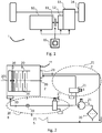
- the powertrain 1 comprises at least one driving motor 10, a gearbox 13, a controlled coupling device 11 and a control device 15 to coordinate them.
- the powertrain 1 is hybrid and is further equipped with a second driving motor 12 which is an electric traction machine mounted between the coupling device 11 and the gearbox 13 thus allowing an all-electric or hybrid driving mode in assistance of the driving motor 10.
- the driving motor 10 is an internal combustion heat engine comprising a linked drive shaft integral in rotation at the input of the coupling device.
- the controlled gearbox 13 comprises a connected primary shaft rotatably fixed at the output of the coupling device and can be configured to apply one or more gear ratios between the heat engine and the wheels 14 of the vehicle.
- the secondary shaft at the output of the gearbox 13 is linked in transmission to the wheels 24 of the vehicle.
- the electric traction machine is mounted on a set of wheels separate from that to which the heat engine is coupled. It is also contemplated to apply the control method for a powertrain having thermal traction only. In this case, the powertrain is not equipped with the electric traction machine 12.
- the coupling device 11 is able to selectively connect the drive shaft and the primary shaft in rotation as a function of a transmissible torque control for transmitting a motor torque to the wheels generated by the heat engine 10.
- the Coupling device 11 is a wet clutch disc device, which is actuated by hydraulic actuation means.
- the coupling device 11 can be controlled in a locked state, an open state and a sliding state, the latter state being used by the invention to increase the temperature of the lubricating fluid.
- the slip state corresponds to a state in which the disks responsible for transmitting the engine torque are in friction with each other. During a slip, only part of the engine torque is transmissible.
- the control of the slip state consists in controlling a transmissible torque which is less than the engine torque at the input of the coupling device 11.
- FIG 2 there is shown more precisely a block diagram of the wet clutch device 11 and the hydraulic actuation means.
- the clutch device 11 is connected at the input to the drive shaft 201 of the heat engine 10 and to the primary shaft 202 of the gearbox.
- the clutch device comprises, arranged alternately with respect to each other others, disks 204 and 205 secured respectively to the drive shaft 201 and to the primary shaft 202.
- a hydraulic piston 203 is movable in translation and can be actuated by the actuating means so as to join and disconnect in rotation the disks 204, 205 depending on the coupling command.
- the actuating means comprise an actuating interface 207 bringing an actuating fluid, such as oil, controlled in pressure or flow in an actuating chamber of the clutch device 11 in contact with the piston 203, a hydraulic actuation circuit 208 in which the actuating fluid circulates, a hydraulic distributor 210 controlled in current as a function of the coupling control, and a sensor for measuring the temperature 209 of the actuating fluid.
- the hydraulic distributor 210 is powered by a hydraulic pump 214 and its function is to regulate the pressure or the output flow in the actuation circuit 208.
- the hydraulic pump 214 also supplies via a bypass a lubrication circuit 212 of the clutch device 11.
- the lubrication circuit comprises a lubrication interface 211 to bring the actuating fluid into the friction zone of the discs 204, 205.
- the lubrication flow is controlled by a hydraulic distributor 213 controlled by current as a function of a lubrication control.
- the hydraulic distributor 213 is fed by the hydraulic pump 214 and there is provided a direct fluid return circuit to a reservoir 215, commonly called a tank.
- the fluid return circuit can be diverted to a device for cooling the fluid before returning to the reservoir 215.
- the hydraulic pump 214 draws the actuating fluid from the reservoir via a filter 206, commonly referred to as strainer.
- the hydraulic distributors 210, 213 are of the current-controlled solenoid valve type and are controlled by the control device 15. The control functions will be described more precisely in the remainder of the description.
- the pump hydraulic 214 supplies exclusively the actuation 208 and lubrication circuits 212.
- the thermal losses of the actuating fluid are reduced as it travels to the reservoir.
- control device 15 comprises one or more integrated circuit computers coupled to memories and intended to perform control functions for the powertrain operation.
- the memories record a control function containing the instructions for executing the control method according to the invention.
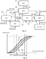
- a first interface module 31 calculates a torque setpoint of the driver's will CS_cvc from the cockpit control interface as a function of acceleration or braking parameters coming from the vehicle speed control devices. , such as a measurement of the position of an acceleration pedal or of a brake pedal by a proportional sensor, or of the depressing speed or of the depressing acceleration of the pedals.
- a second distribution module 32 calculates torque setpoints to be distributed between the torque actuators of the drive train, in particular an engine torque setpoint CS_mth intended for a control module 33 of the heat engine 10, a transmissible torque setpoint CS_emb to destination of a control module 35 of the clutch device 11 and an electric motor torque setpoint CS_mel intended for a control module 37 of the electric traction machine 12.
- the control module 33 of the thermal engine issues a command of engine torque CA_mth destined for motor 10.
- the control module 35 sends CA_act coupling commands to a control module 36 controlling the hydraulic distributor 210 and the hydraulic distributor 213.
- the pilot module 36 controls the distributors 210 , 213 according to the CA_act coupling commands to control by a control current a flow rate or a pressure of the actuating fluid in the cir actuator 208 and the lubrication circuit 212.
- the controlled pressure corresponds to a transmissible torque sought and operated by the clutch device 11.
- the control module 37 of the electric traction machine 12 receives an electric motor torque setpoint CS_mel coming from the distribution module 32 and generates an electric motor torque command CA_mel of the electric traction machine, in particular to transmit a torque to the wheels or generate braking torque.
- the control device 15 comprises a thermal regulation module 34 of the actuating fluid which is in charge of controlling the sliding state of the valve. clutch device 11 in order to increase the temperature of the actuating fluid Tcc when the latter is below a predetermined temperature threshold Ts.
- the thermal regulation module 34 is able to determine, on the one hand, the temperature Tcc of the actuating fluid in the actuation circuit 208, in particular from the sensor 209, and on the other hand the predetermined temperature threshold Ts of the actuation fluid.
- the temperature of the actuating fluid Tcc is determined from an estimate of the temperature calculated by software means based on the instantaneous transmission characteristics of the clutch device 11, for example according to the teaching of the patent document FR2883609A1 cited above in the state of the art.
- the thermal regulation module 34 calculates slip setpoints CS_gl1, CS_gl2, CS_gl3 intended respectively for the control module 33 of the heat engine 10, the control module 35 of the clutch device 11 and the control module 37 of the electric traction machine 12.
- the slip setpoints CS_gl1, CS_gl2 introduce a slip torque CP_gl and the setpoint CS_gl3 a slip compensation torque which can be of the same value as the slip torque CP_gl.
- the slip torque CP_gl is configured so that the transmissible torque command CA_act of the clutch device 11 becomes less than the engine torque command CA_mth at its input.
- the discs 204, 205 then enter a state of friction.
- the setpoint CS_gl1 controls a sliding torque that can be introduced by the heat engine 10 to bring the clutch device 11 into a sliding state. This sliding torque is added in addition to the engine torque setpoint CS_mth calculated by the distribution module 32.
- the setpoint CS_gl2 comprises at least one setpoint for controlling the flow rate of the fluid for actuating the lubrication circuit 212 so as to allow the return of the actuating fluid, which has been brought to the desired temperature during the slip state, to the reservoir 215 so that the latter is then brought to the actuation circuit 208 to improve the response accuracy dispenser 210.
- the setpoint CS_gl2 furthermore comprises a setpoint for actuating the actuation circuit 208 of the clutch device 11 in order to control a slip state when the slip is not caused by a change in the torque setpoint CS_mth.
- the setpoint CS_gl3 controls a compensation torque that can be introduced by the electric traction machine 12 to compensate for the loss of torque linked to the slip. This variant of the process will be described in the remainder of the description.
- the predetermined temperature threshold Ts depends on the type and size of the distributor 210. It is chosen, for example, at a temperature value of around 20 ° C. More generally, it is configured at a value for which a response from the distributor 210 to the transmissible torque setpoint CS_emb has a minimum level of dispersion, this value being indicated by the data supplied by the manufacturer of the distributor 210. It is known that the Dispersion in operation of a solenoid valve is attributable to the viscosity of the actuating fluid as well as to the expansion characteristics of its components. The control current causes a displacement of the solenoid valve core which creates a more or less important opening of the circuit. This opening has an opening section which can introduce pressure drops sensitive to the temperature of the actuating fluid.
- the figure 4 illustrates this dispersal effect.
- Two dispersion hystereses of the response of distributor 210 are shown as a function of the temperature of the actuating fluid supplied to it.
- On the abscissa is represented the control current of distributor 210 and the response in pressure or flow rate is ordered.
- the response curve C1 corresponds to a temperature of the actuating fluid lower than that of the curve C2.
- the linear operating range PL1 of curve C1 is smaller than the linear operating plate PL2 of curve C2.
- the widening of the linear operating range and of the valve piloting trip thresholds improves piloting precision.
- the invention makes it possible to bring the temperature of the fluid of the actuation circuit to a temperature for which the dispersion curve in response exhibits the lowest hysteresis.
- the figure 5 represents the control method according to the invention to improve the control precision of the actuation circuit
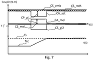
- the figures 6 and 7 represent the values of the drive train control setpoints during the execution of the method according to the invention.
- a first step 50 the vehicle is moving in a situation for which an engine torque is requested by the driver.
- the powertrain control method therefore controls at this step, a torque setpoint CS_cvc calculated from the driver's wishes, an engine torque setpoint CS_mth and an electric motor torque setpoint CS_mel, both in response to the CS_cvc setpoint , and a torque setpoint CS_emb transmissible by the clutch device 11 to allow transmission of the engine torque CS_mth to the wheels of the vehicle.
- the method comprises a step of verifying the capacity of the heat engine 10 and of the electric traction machine 12 to supply an additional torque to the engine torque setpoint CS_mth and to the engine torque setpoint CS_mel respectively. This is in order to introduce a slippage state of the clutch or to compensate for the slip state.
- the method further comprises determining a maximum engine torque CPmax that can be delivered by the heat engine 10 and the electric traction machine 12, and if the maximum engine torque CPmax is greater than the instantaneous engine torque CS_cvc which is delivered both by the heat engine 10 and by the electric traction machine 12, the increase in the engine torque setpoint CS_mth by the setpoint CS_gl1 is authorized, or the increase in the motor setpoint CS_mel by the setpoint CS_gl3 is authorized , according to which of the two engines is able to increase its load.
- the control method is then brought to step 52.
- step 57 which consists of maintaining the clutch device in a locked state or at least in a slip-free condition to avoid deteriorating drivability.
- step 52 the method then checks the temperature of the actuating fluid.
- the method comprises a step of temperature measurement by the sensor 209 positioned in the actuation circuit 208. The precision of the temperature measurement is thus improved.
- the temperature is determined by calculation according to a method described above.
- the method comprises a step of controlling the slip state according to the slip torque CP_gl to bring the temperature of the fluid d 'actuation above the temperature threshold. More specifically, an engine torque setpoint of at least one of the two driving motors of the power train 1, either of the heat engine 10 or of the electric traction machine 12, is increased by the value of the sliding torque. This situation is maintained as long as the temperature Tcc is below the threshold Ts.
- the value of the sliding torque CP_gl controlled by the method is a constant predetermined value. Nevertheless, it is conceivable that the sliding torque is a variable value, for example as a function of the temperature difference between the temperature of the actuating fluid Tcc and the temperature threshold Ts.
- a step 54 is provided for arbitration between the two possible modes for controlling the slip state, these modes being represented by steps 55, 56 on the figures 6 , 7 respectively.
- the arbitration is performed according to a priority criterion, favoring one of the two driving motors, and according to the capacity of each of the driving motors 10,12 of the powertrain 1 to provide an additional engine torque corresponding to the slip torque.
- the method comprises comparing the control of the motor torque CA_mth and a maximum torque Cmax10 that can be delivered by the heat engine 10, and when the control of the motor torque CA_mth is equal to the torque maximum Cmax10, the slip state is controlled according to the second mode 56, if not according to the first mode.
- the arbitration function is executed by the control module 34 of the thermal regulation.
- the slip state is caused by the increase in torque of the heat engine 10.
- the arbitration function has detected that the heat engine 10 has a maximum capacity Cmax10 which is greater than the instantaneous motor torque CA_mth.
- the control method controls the powertrain so that the transmissible torque command CA_act has a value lower than the engine torque command CA_mth.
- the setpoint CS_mth is increased by the value of the sliding torque CP_gl, and the command CA_act of the clutch device 11 is equal to the value of the setpoint CS_emb.
- the setpoint CS_emb is constant and has the same value as the setpoint CS_mth shown in dotted lines.
- the additional sliding torque CP_gl is therefore dissipated by the discs 204, 205 of the clutch device 11 and causes the temperature of the actuating fluid to rise.
- the lubrication circuit 212 is controlled by the circulation of fluid to bring the heated fluid to the reservoir 215.
- the temperature of the actuating fluid Tcc is below the threshold Ts, and the clutch device is in the locked state.
- the setpoint CS_mth is increased by the slip torque CP_gl as long as the temperature Tcc of the actuating fluid is below the threshold Ts. It will be noted that in this situation, the total engine torque CS_cvc to be transmitted to the wheels in response to the driver's wishes is only generated by the heat engine 10, the setpoint CS_mel is zero throughout this situation.
- the slip state is caused by a decrease in the transmissible torque command CA_act of the clutch device 11.
- the arbitration function has detected that the heat engine 10 is operating at its maximum capacity Cmax10 and the slip state is then controlled by a modification of the transmissible torque of the clutch device 11.
- step 56 the control method controls the powertrain so that the transmissible torque command CA_act has a value less than the first engine torque command CA_mth which is equal to the setpoint CS_mth shown in dotted lines.
- the transmissible torque setpoint CS_emb (which is equal to the value of the setpoint CS_mth) is reduced by the slip torque CP_gl according to the setpoint CS_gl2, and the electric motor torque setpoint CS_mel is increased by the value of the sliding torque CP_gl according to the setpoint CS_gl3 so as to compensate for the loss of torque resulting from the slip.
- the decrease in the transmissible torque CA_act causes a state of heat dissipation at the level of the disks. This results in a rise in temperature of the actuating fluid.
- the lubrication circuit 212 is controlled in the circulation of fluid to bring the heated fluid to the reservoir 215 and the sliding state is controlled as long as the temperature Tcc of the actuating fluid is below the threshold Ts.
- the sliding torque CP_gl can have a torque value different from the compensation torque of the electric machine.
- the state of locking of the clutch device it is common for the state of locking of the clutch device to be controlled by a transmissible torque command greater than the engine torque to be transmitted according to a predetermined torque difference in order to guarantee locking. This therefore results in a sliding torque value that must take this torque difference into account.
- the hydraulic pump 214 supplies another actuation circuit for example controlling a second device. 'clutch.
- this other actuation circuit is supplied with the actuation fluid used for lubricating the first clutch device and also benefits from the thermal regulation of the actuation fluid implemented by the invention.
- the method also applies to a thermal traction vehicle only.
- the slip state is controlled by the heat engine by controlling an engine torque greater than the torque transmissible by the clutch device, and the arbitration step 54 of the method is then not necessary.
- the method applies to an electric traction module in which the driving motor at the input of the coupling device is an electric traction machine.
- the coupling device may for example be a multi-plate clutch device, a clutch device with two friction plates or a wet clutch device.
Landscapes
- Physics & Mathematics (AREA)
- Fluid Mechanics (AREA)
- Engineering & Computer Science (AREA)
- General Engineering & Computer Science (AREA)
- Mechanical Engineering (AREA)
- Hybrid Electric Vehicles (AREA)
- Hydraulic Clutches, Magnetic Clutches, Fluid Clutches, And Fluid Joints (AREA)
Claims (10)
- Verfahren zum Steuern eines Antriebsstrangs (1) eines Kraftfahrzeugs zum Regulieren der Temperatur des Betätigungsfluids, das einen Hydraulikverteiler (210) eines Betätigungskreises (208) des Antriebsstrangs versorgt, wobei der Antriebsstrang umfasst ferner eine Kupplungsvorrichtung (11), die durch einen übertragbaren Drehmomentsollwert (CS_emb) gesteuert wird, wobei die Kupplungsvorrichtung (11) mit einer Schmierschaltung (212) verbunden ist angetrieben durch das Betätigungsfluid, wobei das Verfahren einen Schritt umfasst, die Bestimmung (52) von temperatur (Tcc) des Betätigungsfluids und einen Schlupfzustand zu steuern (53) der Kupplungsvorrichtung (11), um die Temperatur des Betätigungsfluids zu modifizieren, gekennzeichnet dadurch, dass ferner das Bestimmen einer vorbestimmten Temperaturschwelle (Ts) des Betätigungsfluids und , wenn die Temperatur des Betätigungsfluids (Tcc) liegt unterhalb der Temperaturschwelle (Ts), der Kontrolle von e der Gleitzustand (53) gemäß einem Gleitdrehmoment (CP_gl) zu bringen, um die Temperatur des Betätigungsströmungsmittels über der Temperaturschwelle (Ts).
- Verfahren nach Anspruch 1, dadurch gekennzeichnet, dass die vorbestimmte temperaturschwelle (Ts) auf einen Wert eingestellt ist, für den eine Verteilerantwort (210) ein Mindestdispersionsniveau aufweist.
- Verfahren nach Anspruch 1 oder 2, dadurch gekennzeichnet, daß die Bestimmung der Temperatur (52) des Betätigungsströmungsmittels einen Schritt umfasst, die Temperatur durch ein Messtemperatursensor (209) von der Betätigungsschaltung (208).
- Verfahren nach einem der Ansprüche 1 bis 3, dadurch gekennzeichnet, dass der Wert des Gleitdrehmoment (CP_gl) ein konstanter vorbestimmter Wert ist.
- Verfahren nach einem der Ansprüche 1 bis 4, dadurch gekennzeichnet, dass die Steuerung des Schlupfzustands (53) einen Steuerschritt (55 ; 56) umfasst, so dass das übertragbare Drehmoment (CA_act) der Vorrichtung Die Kupplung (11) ist kleiner als der Drehmomentmotor (CA_mth) eines ersten Motors, der das Triebwerk der Gruppe antreibt (10), wobei der erste Motor, der das (10) antreibt, am Eingang der Kupplungsvorrichtung (11) angeschlossen ist.
- Verfahren nach Anspruch 5, dadurch gekennzeichnet, dass es ferner die Bestimmung eines maximales Motordrehmoments (CPmax) durch ausgegeben
werden mindestens die genannte erster Motor führende (10) und, wenn das maximalen Motordrehmoment (CPmax) das Motordrehmoment größer ist als durch geliefert zumindest die die ersten Antriebsmotor (10), die Steuerung des Schlupfzustandes (53) erlaubt ist. - Verfahren nach einem der Ansprüche 5 bis 6, dadurch gekennzeichnet, dass die Steuerung des Gleitzustands (53) gemäß einem ersten Modus (55) gesteuert wird, in dem der
erste Antriebsmotor (10) das Gleitmoment einführt (CP_gl), so dass das übertragbare Drehmoment (CA_act) der Kupplungsvorrichtung (11) geringer ist als das Motordrehmoment (CA_mth) des ersten Antriebsmotors (10). - Verfahren nach Anspruch 7, Antriebsstrang comport ant ferner ein zweiter Antriebsmotor (12) geeignet ist, ein Motordrehmoment zu übertragen (CA_mel) an die Rädern, dadurch gekennzeichnet, dass es ferner einen Schritt des Schiedsverfahrens (54) Steuerung des Schlupfzustands (53) zwischen dem ersten Modus (55) und einem zweiten Modus (56), und wenn die Steuerung des Schlupfzustands (53) gemäß dem zweiten Modus (56) gesteuert wird, das Verfahren ferner die Verringerung des übertragbaren Drehmoments der Kupplungsvorrichtung (11) nach dem Gleitdrehmoment (CP_gl) aus, so dass das übertragbare Drehmoment (CA_act) der Kupplungsvorrichtung (11) geringer ist als der Drehmomentmotor (CA_mth) der genannten ersten Motor führende (10) und die Einführung von Drehmoment (CA_mel) durch den zweiten Motor führenden (12), um den Verlust an Drehmoment von dem Schiebe resultierenden zu kompensieren .
- Verfahren nach Anspruch 8, dadurch gekennzeichnet, dass die Arbitrierung Schritt (54) den Vergleich von dem Motordrehmoment (CA_mth) von dem ersten Antriebsmotor (10) und ein maximales Drehmoment (Cmax10), die durch zugestellt werden kann der Erste Motor führende (10) und, wenn das Motordrehmoment (CA_mth) gleich ist das maximale Drehmoment (Cmax10), wird der Schlupfzustand gemäß der zweiten Führung (56) gesteuert wird.
- Kraftfahrzeug mit einem von einer Steuervorrichtung gesteuerten Antriebsstrang (1), der dadurch gekennzeichnet ist, dass die Steuervorrichtung das Verfahren gemäß einem der Ansprüche 1 bis 9 ausführt.
Applications Claiming Priority (2)
| Application Number | Priority Date | Filing Date | Title |
|---|---|---|---|
| FR1754229A FR3066242B1 (fr) | 2017-05-15 | 2017-05-15 | Procede de controle d'un groupe motopropulseur pour la regulation thermique d'un circuit hydraulique |
| PCT/FR2018/050948 WO2018211189A1 (fr) | 2017-05-15 | 2018-04-16 | Procede de controle d'un groupe motopropulseur pour la regulation thermique d'un circuit hydraulique |
Publications (2)
| Publication Number | Publication Date |
|---|---|
| EP3625472A1 EP3625472A1 (de) | 2020-03-25 |
| EP3625472B1 true EP3625472B1 (de) | 2021-01-20 |
Family
ID=59153172
Family Applications (1)
| Application Number | Title | Priority Date | Filing Date |
|---|---|---|---|
| EP18719979.9A Active EP3625472B1 (de) | 2017-05-15 | 2018-04-16 | Verfahren zur steuerung eines antriebsstrangs zur thermischen regelung eines hydraulikkreises |
Country Status (4)
| Country | Link |
|---|---|
| EP (1) | EP3625472B1 (de) |
| CN (1) | CN110651131B (de) |
| FR (1) | FR3066242B1 (de) |
| WO (1) | WO2018211189A1 (de) |
Family Cites Families (19)
| Publication number | Priority date | Publication date | Assignee | Title |
|---|---|---|---|---|
| DE10045758A1 (de) | 2000-09-15 | 2002-03-28 | Bosch Gmbh Robert | Verfahren und Einrichtung zum Betrieb einer Kupplung |
| JP3744414B2 (ja) * | 2001-11-29 | 2006-02-08 | トヨタ自動車株式会社 | 車両の制御装置 |
| US6715597B1 (en) * | 2002-10-25 | 2004-04-06 | Borgwarner, Inc. | Dual clutch transmission clutch cooling control method |
| FR2883609B1 (fr) | 2005-03-25 | 2007-06-01 | Renault Sas | Procede de commande du glissement d'un systeme d'embrayage humide |
| JP2007126040A (ja) * | 2005-11-04 | 2007-05-24 | Toyota Motor Corp | 車両の制御装置 |
| US8079933B2 (en) * | 2007-11-04 | 2011-12-20 | GM Global Technology Operations LLC | Method and apparatus to control engine torque to peak main pressure for a hybrid powertrain system |
| FR2933913B1 (fr) | 2008-07-16 | 2011-01-14 | Renault Sas | Dispositif de commande adaptative a l'evolution de la caracteristique d'un embrayage en fonction de la temperature applique a un vehicule equipe d'un systeme 4x4 pilote. |
| JP5402060B2 (ja) * | 2009-02-17 | 2014-01-29 | 日産自動車株式会社 | 電動車両の制御装置 |
| US8155850B2 (en) * | 2009-07-23 | 2012-04-10 | GM Global Technology Operations LLC | System for controlling peak torque in manual transmissions |
| JP4913848B2 (ja) * | 2009-07-28 | 2012-04-11 | 本田技研工業株式会社 | 自動変速機の制御装置 |
| FR2965779B1 (fr) * | 2010-10-11 | 2013-06-14 | Peugeot Citroen Automobiles Sa | Procede de commande d'un demarrage d'un vehicule equipe d'un systeme de mise en veille d'un moteur |
| US8731793B2 (en) * | 2010-12-29 | 2014-05-20 | Caterpillar Inc. | Clutch temperature estimation for a mobile machine |
| US8915076B2 (en) * | 2011-01-12 | 2014-12-23 | Gm Global Technology Operations, Llc | Transmission hydraulic control system having flow augmentation |
| US8855876B2 (en) * | 2011-07-21 | 2014-10-07 | Honda Motor Co., Ltd. | System and method for managing an operating temperature of a working fluid in a vehicle powertrain |
| JP6111077B2 (ja) * | 2013-01-17 | 2017-04-05 | 株式会社エフ・シー・シー | 動力伝達装置 |
| DE102014225657A1 (de) * | 2014-12-12 | 2016-06-16 | Schaeffler Technologies AG & Co. KG | Verfahren zur Steuerung einer Kühlung einer Kupplung für ein Kraftfahrzeug |
| JP2016222151A (ja) * | 2015-06-01 | 2016-12-28 | アイシン精機株式会社 | クラッチ特性学習装置 |
| US20160041066A1 (en) * | 2015-10-23 | 2016-02-11 | Caterpillar Inc. | Method for monitoring temperature of clutch assembly |
| CN106347372B (zh) * | 2016-11-15 | 2018-11-02 | 安徽江淮汽车集团股份有限公司 | 一种半联动点确定方法及系统 |
-
2017
- 2017-05-15 FR FR1754229A patent/FR3066242B1/fr not_active Expired - Fee Related
-
2018
- 2018-04-16 EP EP18719979.9A patent/EP3625472B1/de active Active
- 2018-04-16 WO PCT/FR2018/050948 patent/WO2018211189A1/fr not_active Ceased
- 2018-04-16 CN CN201880032024.1A patent/CN110651131B/zh active Active
Non-Patent Citations (1)
| Title |
|---|
| None * |
Also Published As
| Publication number | Publication date |
|---|---|
| CN110651131B (zh) | 2021-04-27 |
| FR3066242A1 (fr) | 2018-11-16 |
| WO2018211189A1 (fr) | 2018-11-22 |
| CN110651131A (zh) | 2020-01-03 |
| FR3066242B1 (fr) | 2019-06-14 |
| EP3625472A1 (de) | 2020-03-25 |
Similar Documents
| Publication | Publication Date | Title |
|---|---|---|
| JP3511958B2 (ja) | ハイブリッド車のクラッチ制御装置 | |
| CN101201022B (zh) | 用于保护汽车传动系中的离合器的方法和控制装置 | |
| CN103802824A (zh) | 学习混合动力车辆的发动机离合器的操作的方法和系统 | |
| FR3005021A1 (fr) | Systeme et procede de commande d'un vehicule automobile en roulage en roue libre | |
| KR102448975B1 (ko) | 감속 기반 브레이크 냉각제 시스템 및 그 방법 | |
| US8262539B2 (en) | Power transmitting apparatus | |
| US9670857B2 (en) | Torque control of a power-plant for launching a vehicle with a manual transmission | |
| CN102224045A (zh) | 在车辆起动阶段控制发动机速度的方法、装置和计算机程序产品 | |
| CN109890674B (zh) | 用于对车辆的马达进行控制的方法 | |
| SE1250320A1 (sv) | Förfarande och system för reglering av ett motorvarvtal vidett fordon | |
| CN106240492A (zh) | 通过调节发动机制动改变车辆中热能水平的方法和总成 | |
| US6322477B1 (en) | Method of and apparatus for influencing the shifting of transmissions in the power trains of motor vehicles | |
| EP3625472B1 (de) | Verfahren zur steuerung eines antriebsstrangs zur thermischen regelung eines hydraulikkreises | |
| EP3615829B1 (de) | Verfahren zur steuerung eines antriebsstrangs eines kraftfahrzeugs zur verhinderung des abwürgens eines motors | |
| CN108779817B (zh) | 用于对车辆的分离离合器的接合点进行适配的方法 | |
| US20190162253A1 (en) | Clutch control device | |
| CN108700139B (zh) | 用于计算混合动力分离离合器的滑摩功率的方法 | |
| EP1505309A2 (de) | Steuerungsverfahren für eine Antriebseinheit mit automatisiertem Getriebe und eine Kupplung | |
| RU2269709C1 (ru) | Система безударного переключения передач | |
| KR102472609B1 (ko) | 마찰 클러치의 드래그 토크의 필요에 따른 감소 방법 | |
| US10851855B2 (en) | Clutch control device | |
| SE524795C2 (sv) | Arrangemang och förfarande för att bromsa ett motorfordon | |
| FR3103440A1 (fr) | Procede de determination du couple transmis par le moteur a la chaine de traction | |
| JP5240062B2 (ja) | 惰行制御装置 | |
| EP1429011A1 (de) | Verfahren und System zur Steuerung des Drehmoments eines Verbrennungsmotors für ein Automobil |
Legal Events
| Date | Code | Title | Description |
|---|---|---|---|
| STAA | Information on the status of an ep patent application or granted ep patent |
Free format text: STATUS: UNKNOWN |
|
| STAA | Information on the status of an ep patent application or granted ep patent |
Free format text: STATUS: THE INTERNATIONAL PUBLICATION HAS BEEN MADE |
|
| PUAI | Public reference made under article 153(3) epc to a published international application that has entered the european phase |
Free format text: ORIGINAL CODE: 0009012 |
|
| STAA | Information on the status of an ep patent application or granted ep patent |
Free format text: STATUS: REQUEST FOR EXAMINATION WAS MADE |
|
| 17P | Request for examination filed |
Effective date: 20191017 |
|
| AK | Designated contracting states |
Kind code of ref document: A1 Designated state(s): AL AT BE BG CH CY CZ DE DK EE ES FI FR GB GR HR HU IE IS IT LI LT LU LV MC MK MT NL NO PL PT RO RS SE SI SK SM TR |
|
| AX | Request for extension of the european patent |
Extension state: BA ME |
|
| DAX | Request for extension of the european patent (deleted) | ||
| RAV | Requested validation state of the european patent: fee paid |
Extension state: MA Effective date: 20191017 |
|
| GRAP | Despatch of communication of intention to grant a patent |
Free format text: ORIGINAL CODE: EPIDOSNIGR1 |
|
| STAA | Information on the status of an ep patent application or granted ep patent |
Free format text: STATUS: GRANT OF PATENT IS INTENDED |
|
| INTG | Intention to grant announced |
Effective date: 20200923 |
|
| RAP1 | Party data changed (applicant data changed or rights of an application transferred) |
Owner name: PSA AUTOMOBILES SA |
|
| GRAS | Grant fee paid |
Free format text: ORIGINAL CODE: EPIDOSNIGR3 |
|
| GRAA | (expected) grant |
Free format text: ORIGINAL CODE: 0009210 |
|
| STAA | Information on the status of an ep patent application or granted ep patent |
Free format text: STATUS: THE PATENT HAS BEEN GRANTED |
|
| AK | Designated contracting states |
Kind code of ref document: B1 Designated state(s): AL AT BE BG CH CY CZ DE DK EE ES FI FR GB GR HR HU IE IS IT LI LT LU LV MC MK MT NL NO PL PT RO RS SE SI SK SM TR |
|
| REG | Reference to a national code |
Ref country code: GB Ref legal event code: FG4D Free format text: NOT ENGLISH |
|
| REG | Reference to a national code |
Ref country code: CH Ref legal event code: EP |
|
| REG | Reference to a national code |
Ref country code: DE Ref legal event code: R096 Ref document number: 602018012086 Country of ref document: DE |
|
| REG | Reference to a national code |
Ref country code: AT Ref legal event code: REF Ref document number: 1356670 Country of ref document: AT Kind code of ref document: T Effective date: 20210215 |
|
| REG | Reference to a national code |
Ref country code: IE Ref legal event code: FG4D Free format text: LANGUAGE OF EP DOCUMENT: FRENCH |
|
| REG | Reference to a national code |
Ref country code: DE Ref legal event code: R084 Ref document number: 602018012086 Country of ref document: DE |
|
| REG | Reference to a national code |
Ref country code: NL Ref legal event code: MP Effective date: 20210120 |
|
| REG | Reference to a national code |
Ref country code: LT Ref legal event code: MG9D |
|
| REG | Reference to a national code |
Ref country code: GB Ref legal event code: 746 Effective date: 20210618 |
|
| REG | Reference to a national code |
Ref country code: AT Ref legal event code: MK05 Ref document number: 1356670 Country of ref document: AT Kind code of ref document: T Effective date: 20210120 |
|
| PG25 | Lapsed in a contracting state [announced via postgrant information from national office to epo] |
Ref country code: LT Free format text: LAPSE BECAUSE OF FAILURE TO SUBMIT A TRANSLATION OF THE DESCRIPTION OR TO PAY THE FEE WITHIN THE PRESCRIBED TIME-LIMIT Effective date: 20210120 Ref country code: NO Free format text: LAPSE BECAUSE OF FAILURE TO SUBMIT A TRANSLATION OF THE DESCRIPTION OR TO PAY THE FEE WITHIN THE PRESCRIBED TIME-LIMIT Effective date: 20210420 Ref country code: PT Free format text: LAPSE BECAUSE OF FAILURE TO SUBMIT A TRANSLATION OF THE DESCRIPTION OR TO PAY THE FEE WITHIN THE PRESCRIBED TIME-LIMIT Effective date: 20210520 Ref country code: HR Free format text: LAPSE BECAUSE OF FAILURE TO SUBMIT A TRANSLATION OF THE DESCRIPTION OR TO PAY THE FEE WITHIN THE PRESCRIBED TIME-LIMIT Effective date: 20210120 Ref country code: FI Free format text: LAPSE BECAUSE OF FAILURE TO SUBMIT A TRANSLATION OF THE DESCRIPTION OR TO PAY THE FEE WITHIN THE PRESCRIBED TIME-LIMIT Effective date: 20210120 Ref country code: GR Free format text: LAPSE BECAUSE OF FAILURE TO SUBMIT A TRANSLATION OF THE DESCRIPTION OR TO PAY THE FEE WITHIN THE PRESCRIBED TIME-LIMIT Effective date: 20210421 Ref country code: BG Free format text: LAPSE BECAUSE OF FAILURE TO SUBMIT A TRANSLATION OF THE DESCRIPTION OR TO PAY THE FEE WITHIN THE PRESCRIBED TIME-LIMIT Effective date: 20210420 |
|
| PG25 | Lapsed in a contracting state [announced via postgrant information from national office to epo] |
Ref country code: RS Free format text: LAPSE BECAUSE OF FAILURE TO SUBMIT A TRANSLATION OF THE DESCRIPTION OR TO PAY THE FEE WITHIN THE PRESCRIBED TIME-LIMIT Effective date: 20210120 Ref country code: LV Free format text: LAPSE BECAUSE OF FAILURE TO SUBMIT A TRANSLATION OF THE DESCRIPTION OR TO PAY THE FEE WITHIN THE PRESCRIBED TIME-LIMIT Effective date: 20210120 Ref country code: PL Free format text: LAPSE BECAUSE OF FAILURE TO SUBMIT A TRANSLATION OF THE DESCRIPTION OR TO PAY THE FEE WITHIN THE PRESCRIBED TIME-LIMIT Effective date: 20210120 Ref country code: AT Free format text: LAPSE BECAUSE OF FAILURE TO SUBMIT A TRANSLATION OF THE DESCRIPTION OR TO PAY THE FEE WITHIN THE PRESCRIBED TIME-LIMIT Effective date: 20210120 Ref country code: SE Free format text: LAPSE BECAUSE OF FAILURE TO SUBMIT A TRANSLATION OF THE DESCRIPTION OR TO PAY THE FEE WITHIN THE PRESCRIBED TIME-LIMIT Effective date: 20210120 |
|
| PG25 | Lapsed in a contracting state [announced via postgrant information from national office to epo] |
Ref country code: IS Free format text: LAPSE BECAUSE OF FAILURE TO SUBMIT A TRANSLATION OF THE DESCRIPTION OR TO PAY THE FEE WITHIN THE PRESCRIBED TIME-LIMIT Effective date: 20210520 |
|
| REG | Reference to a national code |
Ref country code: DE Ref legal event code: R097 Ref document number: 602018012086 Country of ref document: DE |
|
| PG25 | Lapsed in a contracting state [announced via postgrant information from national office to epo] |
Ref country code: SM Free format text: LAPSE BECAUSE OF FAILURE TO SUBMIT A TRANSLATION OF THE DESCRIPTION OR TO PAY THE FEE WITHIN THE PRESCRIBED TIME-LIMIT Effective date: 20210120 Ref country code: CZ Free format text: LAPSE BECAUSE OF FAILURE TO SUBMIT A TRANSLATION OF THE DESCRIPTION OR TO PAY THE FEE WITHIN THE PRESCRIBED TIME-LIMIT Effective date: 20210120 Ref country code: EE Free format text: LAPSE BECAUSE OF FAILURE TO SUBMIT A TRANSLATION OF THE DESCRIPTION OR TO PAY THE FEE WITHIN THE PRESCRIBED TIME-LIMIT Effective date: 20210120 |
|
| PLBE | No opposition filed within time limit |
Free format text: ORIGINAL CODE: 0009261 |
|
| STAA | Information on the status of an ep patent application or granted ep patent |
Free format text: STATUS: NO OPPOSITION FILED WITHIN TIME LIMIT |
|
| PG25 | Lapsed in a contracting state [announced via postgrant information from national office to epo] |
Ref country code: MC Free format text: LAPSE BECAUSE OF FAILURE TO SUBMIT A TRANSLATION OF THE DESCRIPTION OR TO PAY THE FEE WITHIN THE PRESCRIBED TIME-LIMIT Effective date: 20210120 Ref country code: DK Free format text: LAPSE BECAUSE OF FAILURE TO SUBMIT A TRANSLATION OF THE DESCRIPTION OR TO PAY THE FEE WITHIN THE PRESCRIBED TIME-LIMIT Effective date: 20210120 Ref country code: SK Free format text: LAPSE BECAUSE OF FAILURE TO SUBMIT A TRANSLATION OF THE DESCRIPTION OR TO PAY THE FEE WITHIN THE PRESCRIBED TIME-LIMIT Effective date: 20210120 Ref country code: RO Free format text: LAPSE BECAUSE OF FAILURE TO SUBMIT A TRANSLATION OF THE DESCRIPTION OR TO PAY THE FEE WITHIN THE PRESCRIBED TIME-LIMIT Effective date: 20210120 |
|
| 26N | No opposition filed |
Effective date: 20211021 |
|
| PG25 | Lapsed in a contracting state [announced via postgrant information from national office to epo] |
Ref country code: LU Free format text: LAPSE BECAUSE OF NON-PAYMENT OF DUE FEES Effective date: 20210416 |
|
| REG | Reference to a national code |
Ref country code: BE Ref legal event code: MM Effective date: 20210430 |
|
| PG25 | Lapsed in a contracting state [announced via postgrant information from national office to epo] |
Ref country code: LI Free format text: LAPSE BECAUSE OF NON-PAYMENT OF DUE FEES Effective date: 20210430 Ref country code: CH Free format text: LAPSE BECAUSE OF NON-PAYMENT OF DUE FEES Effective date: 20210430 Ref country code: AL Free format text: LAPSE BECAUSE OF FAILURE TO SUBMIT A TRANSLATION OF THE DESCRIPTION OR TO PAY THE FEE WITHIN THE PRESCRIBED TIME-LIMIT Effective date: 20210120 Ref country code: ES Free format text: LAPSE BECAUSE OF FAILURE TO SUBMIT A TRANSLATION OF THE DESCRIPTION OR TO PAY THE FEE WITHIN THE PRESCRIBED TIME-LIMIT Effective date: 20210120 |
|
| PG25 | Lapsed in a contracting state [announced via postgrant information from national office to epo] |
Ref country code: SI Free format text: LAPSE BECAUSE OF FAILURE TO SUBMIT A TRANSLATION OF THE DESCRIPTION OR TO PAY THE FEE WITHIN THE PRESCRIBED TIME-LIMIT Effective date: 20210120 |
|
| PG25 | Lapsed in a contracting state [announced via postgrant information from national office to epo] |
Ref country code: IT Free format text: LAPSE BECAUSE OF FAILURE TO SUBMIT A TRANSLATION OF THE DESCRIPTION OR TO PAY THE FEE WITHIN THE PRESCRIBED TIME-LIMIT Effective date: 20210120 Ref country code: IE Free format text: LAPSE BECAUSE OF NON-PAYMENT OF DUE FEES Effective date: 20210416 |
|
| PG25 | Lapsed in a contracting state [announced via postgrant information from national office to epo] |
Ref country code: IS Free format text: LAPSE BECAUSE OF FAILURE TO SUBMIT A TRANSLATION OF THE DESCRIPTION OR TO PAY THE FEE WITHIN THE PRESCRIBED TIME-LIMIT Effective date: 20210520 |
|
| PG25 | Lapsed in a contracting state [announced via postgrant information from national office to epo] |
Ref country code: BE Free format text: LAPSE BECAUSE OF NON-PAYMENT OF DUE FEES Effective date: 20210430 |
|
| PG25 | Lapsed in a contracting state [announced via postgrant information from national office to epo] |
Ref country code: NL Free format text: LAPSE BECAUSE OF NON-PAYMENT OF DUE FEES Effective date: 20210120 Ref country code: CY Free format text: LAPSE BECAUSE OF FAILURE TO SUBMIT A TRANSLATION OF THE DESCRIPTION OR TO PAY THE FEE WITHIN THE PRESCRIBED TIME-LIMIT Effective date: 20210120 |
|
| PG25 | Lapsed in a contracting state [announced via postgrant information from national office to epo] |
Ref country code: HU Free format text: LAPSE BECAUSE OF FAILURE TO SUBMIT A TRANSLATION OF THE DESCRIPTION OR TO PAY THE FEE WITHIN THE PRESCRIBED TIME-LIMIT; INVALID AB INITIO Effective date: 20180416 |
|
| REG | Reference to a national code |
Ref country code: DE Ref legal event code: R081 Ref document number: 602018012086 Country of ref document: DE Owner name: STELLANTIS AUTO SAS, FR Free format text: FORMER OWNER: PSA AUTOMOBILES SA, POISSY, FR |
|
| PG25 | Lapsed in a contracting state [announced via postgrant information from national office to epo] |
Ref country code: MK Free format text: LAPSE BECAUSE OF FAILURE TO SUBMIT A TRANSLATION OF THE DESCRIPTION OR TO PAY THE FEE WITHIN THE PRESCRIBED TIME-LIMIT Effective date: 20210120 |
|
| VS25 | Lapsed in a validation state [announced via postgrant information from nat. office to epo] |
Ref country code: MA Free format text: LAPSE BECAUSE OF FAILURE TO SUBMIT A TRANSLATION OF THE DESCRIPTION OR TO PAY THE FEE WITHIN THE PRESCRIBED TIME-LIMIT Effective date: 20210120 |
|
| PG25 | Lapsed in a contracting state [announced via postgrant information from national office to epo] |
Ref country code: TR Free format text: LAPSE BECAUSE OF FAILURE TO SUBMIT A TRANSLATION OF THE DESCRIPTION OR TO PAY THE FEE WITHIN THE PRESCRIBED TIME-LIMIT Effective date: 20210120 |
|
| PG25 | Lapsed in a contracting state [announced via postgrant information from national office to epo] |
Ref country code: MT Free format text: LAPSE BECAUSE OF FAILURE TO SUBMIT A TRANSLATION OF THE DESCRIPTION OR TO PAY THE FEE WITHIN THE PRESCRIBED TIME-LIMIT Effective date: 20210120 |
|
| PGFP | Annual fee paid to national office [announced via postgrant information from national office to epo] |
Ref country code: DE Payment date: 20250319 Year of fee payment: 8 |
|
| PGFP | Annual fee paid to national office [announced via postgrant information from national office to epo] |
Ref country code: GB Payment date: 20260319 Year of fee payment: 9 |
|
| PGFP | Annual fee paid to national office [announced via postgrant information from national office to epo] |
Ref country code: FR Payment date: 20260319 Year of fee payment: 9 |