EP1505351B1 - Appareil de cuisson avec un dispositif d'éclairage - Google Patents
Appareil de cuisson avec un dispositif d'éclairage Download PDFInfo
- Publication number
- EP1505351B1 EP1505351B1 EP04016562A EP04016562A EP1505351B1 EP 1505351 B1 EP1505351 B1 EP 1505351B1 EP 04016562 A EP04016562 A EP 04016562A EP 04016562 A EP04016562 A EP 04016562A EP 1505351 B1 EP1505351 B1 EP 1505351B1
- Authority
- EP
- European Patent Office
- Prior art keywords
- housing part
- domestic appliance
- appliance according
- cover glass
- incision
- Prior art date
- Legal status (The legal status is an assumption and is not a legal conclusion. Google has not performed a legal analysis and makes no representation as to the accuracy of the status listed.)
- Expired - Lifetime
Links
- 238000010411 cooking Methods 0.000 title claims abstract description 14
- 239000006059 cover glass Substances 0.000 claims abstract description 50
- 238000005286 illumination Methods 0.000 claims abstract description 4
- 239000002184 metal Substances 0.000 claims description 8
- 238000005520 cutting process Methods 0.000 claims description 3
- 238000000034 method Methods 0.000 claims description 3
- 238000004049 embossing Methods 0.000 description 8
- 238000010586 diagram Methods 0.000 description 5
- 210000002414 leg Anatomy 0.000 description 4
- 238000005452 bending Methods 0.000 description 3
- 238000005516 engineering process Methods 0.000 description 2
- 230000002349 favourable effect Effects 0.000 description 2
- 238000004519 manufacturing process Methods 0.000 description 2
- 230000007704 transition Effects 0.000 description 2
- 230000001154 acute effect Effects 0.000 description 1
- 230000006378 damage Effects 0.000 description 1
- 210000003414 extremity Anatomy 0.000 description 1
- 238000010304 firing Methods 0.000 description 1
- 238000003780 insertion Methods 0.000 description 1
- 230000037431 insertion Effects 0.000 description 1
- 239000000463 material Substances 0.000 description 1
- 239000007787 solid Substances 0.000 description 1
- 210000000689 upper leg Anatomy 0.000 description 1
Images


Classifications
-
- F—MECHANICAL ENGINEERING; LIGHTING; HEATING; WEAPONS; BLASTING
- F21—LIGHTING
- F21V—FUNCTIONAL FEATURES OR DETAILS OF LIGHTING DEVICES OR SYSTEMS THEREOF; STRUCTURAL COMBINATIONS OF LIGHTING DEVICES WITH OTHER ARTICLES, NOT OTHERWISE PROVIDED FOR
- F21V3/00—Globes; Bowls; Cover glasses
-
- F—MECHANICAL ENGINEERING; LIGHTING; HEATING; WEAPONS; BLASTING
- F21—LIGHTING
- F21V—FUNCTIONAL FEATURES OR DETAILS OF LIGHTING DEVICES OR SYSTEMS THEREOF; STRUCTURAL COMBINATIONS OF LIGHTING DEVICES WITH OTHER ARTICLES, NOT OTHERWISE PROVIDED FOR
- F21V17/00—Fastening of component parts of lighting devices, e.g. shades, globes, refractors, reflectors, filters, screens, grids or protective cages
- F21V17/10—Fastening of component parts of lighting devices, e.g. shades, globes, refractors, reflectors, filters, screens, grids or protective cages characterised by specific fastening means or way of fastening
- F21V17/12—Fastening of component parts of lighting devices, e.g. shades, globes, refractors, reflectors, filters, screens, grids or protective cages characterised by specific fastening means or way of fastening by screwing
-
- F—MECHANICAL ENGINEERING; LIGHTING; HEATING; WEAPONS; BLASTING
- F24—HEATING; RANGES; VENTILATING
- F24C—DOMESTIC STOVES OR RANGES ; DETAILS OF DOMESTIC STOVES OR RANGES, OF GENERAL APPLICATION
- F24C15/00—Details
- F24C15/008—Illumination for oven cavities
-
- F—MECHANICAL ENGINEERING; LIGHTING; HEATING; WEAPONS; BLASTING
- F21—LIGHTING
- F21W—INDEXING SCHEME ASSOCIATED WITH SUBCLASSES F21K, F21L, F21S and F21V, RELATING TO USES OR APPLICATIONS OF LIGHTING DEVICES OR SYSTEMS
- F21W2131/00—Use or application of lighting devices or systems not provided for in codes F21W2102/00-F21W2121/00
- F21W2131/30—Lighting for domestic or personal use
- F21W2131/307—Lighting for domestic or personal use for ovens
Definitions
- the invention relates to a household appliance, in particular cooking appliance with a lighting device for illuminating a cooking chamber, which has a housing part for a lamp and a cover glass.
- the housing part has a thread for screwing the cover glass into the housing part.
- a generic cooking appliance which has a lighting device for illuminating a cooking chamber.
- the lighting device consists of a housing part for a lamp and a cover glass for screwing into the housing part.
- the cover glass has a threaded collar and a support surface, which is opposite to a flange edge of the housing part in threaded position.
- the support surface of the cover glass is arranged in the screw-in end position with a small distance from the flange edge of the housing.
- an electric lamp for the muffle room of a baking and roasting oven with a transparent lamp cover and a metal housing which is insertable in an opening in one of the muffle walls, wherein the transparent lamp cover is screwed with a fferansatz in the metal housing.
- the metal housing is attached to the outside of the Muffelraumwand, wherein the lamp cover is screwed with the interposition of a force acting against the inside of the Muffelraumwand metal ring in the metal housing.
- the object of the present invention is to provide a household appliance, in particular cooking appliance with a lighting device in which an assembly or disassembly of the cover glass is simplified.
- the housing part has a spring portion, in which at least partially the housing-side thread is formed.
- the spring portion of the thread of the housing part is given an elasticity.
- Such solid burning can occur at oven temperatures above about 300 ° C when the screwed cover glass is supported on a flange of the housing part.
- a thread segment is at least partially formed. Thus, only a portion of the thread segment is formed elastically, while the rigidity of the housing part is maintained.
- the housing part is made of a sheet metal.
- the housing part can advantageously be manufactured as a stamped and bent part in terms of manufacturing technology.
- the thread in the housing part is formed by a number of thread segments. These may be embossed in a side wall of the housing part and protrude radially into a housing part interior.
- the housing part overall or its thread segments can be given increased elasticity. A reduction in the sheet thickness, however, can lead to the fact that it comes faster when tightening the cover glass to a disadvantageous plastic deformation of the housing part.
- a spring constant of the housing-side spring section increases in a screwing-in direction of the cover glass. This achieves the most continuous and slowly increasing increase of a screw-in torque.
- the spring portion may be formed by a spring flap freely cut in the housing part.
- the spring tab may be U-shaped or triangular cut from the housing part and bent over a bending edge of the housing side wall.
- the triangular spring flap is stiffer for geometric reasons than a comparable U-shaped spring flap. Due to the stiffer triangular spring flap overtightening of the cover glass in the housing-side thread is sufficiently prevented.
- the triangular shape of the spring tab is limited by an angled cutout in the housing part and by a bending edge around which the spring tabs can bend.
- a free end of the spring tab is aligned against a screwing-in direction of the cover glass.
- screwing in the cover glass therefore first increases the easier bendable free end of the spring clip the screwing. Only then follows a spring load through the remaining spring tabs on the cover glass.
- the spring tabs can be easily formed by an incision in the housing part.
- the incision consists of two incision legs, which are angled to each other.
- the spring constant of the spring flap can be influenced by a change in the angle enclosed by the two incision thighs: at an acute angle, the spring constant of the spring flap is too low. At an obtuse angle, too large a spring constant of the spring flap arises. It has proved to be particularly advantageous if the two incision limbs are angled away from each other substantially at right angles. In this case, almost a favorable linear increase of the Einschraubwindmonents over the entire rotation angle range of the cover glass can be achieved.
- the incision arises at least partially automatically during a stamping process for the thread segments.
- the incision during embossing is torn by itself in the side wall of the housing part.
- the incision is at least partially formed by a cutting process.
- a first incision legs extend substantially in the screwing and through Embossing be formed.
- a second leg may extend substantially in an axial direction of the housing part and be formed by a cutting process.
- the housing part has additional stiffening sections. This ensures - despite the spring portion - a stable shape of the housing part, which is required for mounting the housing part in the oven.
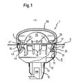
- a lighting device 1 is shown, which is installed in a mounting opening 3 of a muffle wall 5 of a cooking appliance.
- the muffle wall 5 defines a cooking chamber 7 of the cooking appliance, which is illuminated by the lighting device 1 in the operating state of the cooking appliance.
- the lighting device has a pot-like, hollow cylindrical housing part 9.
- the housing part 9 is made as a stamped and bent part of a sheet material having a sheet thickness d of about 0.3 mm.
- a cylindrical side wall 11 of the housing part 9 has a cone-like transition 12 to a housing part bottom.
- a central passage opening 13 is formed, in which a lamp base 15 is inserted with the lamp 16 screwed.
- the housing part bottom opposite the hollow cylindrical housing part 9 is formed open at the top.
- the side wall 11 merges at the side opposite the housing part bottom in a flange 17, which is angled outwards.
- the hollow cylindrical design, the cone-like transition 12 and the angled flange edge 17 ensure a high dimensional stability of the housing part.
- the flange edge 17 of the housing part 9 surrounds a screw-in opening 29 for a cover glass 30.
- thread segments 31 are impressed in the side wall 11 of the housing part, which protrude into the interior of the housing part 9.
- the thread segments 31 lie along an imaginary dot-dash line in the FIG. 2
- the helix corresponds to the pitch of the thread 37 in the cover glass 30.
- each of the thread segments 31 is formed into the side wall 11 in a stamping operation.
- Each thread segment 31 is formed approximately pocket-shaped with a lower flank surface 32 and an upwardly open embossing opening 33.
- the embossing opening 33 is automatically torn in the side wall 11 during the embossing process. It is according to the FIG. 2 an elongated slot having a length I 1 of about 9 mm, which extends in the direction of insertion E.
- the lower flank surface 32 of the thread segment 31 comes into contact with the thread 37 of the cover glass when the cover glass 30 is tightened.
- the embossing opening 33 is extended by a slot 43.
- the slot 43 extends along an axial direction A.
- the slot 43 has a length l 2 of about 3 mm.
- the embossing opening 33 and the slot 43 form each other at right angles angled legs, the longitudinal sides are spaced from each other without contact.
- a gap width s of the slot 43 is about 0.3 mm.
- the embossing opening 33 and the slot 43 form a cut-free spring tab 44.
- the spring tab 44 is triangular shaped and one in the FIG. 2 dashed lines shown bending line b bendable. In the spring tab 44, a threaded segment 31 is formed in each case.
- the thread segments 31 is given an elasticity, which in the FIG. 2 is represented by a characteristic of the spring constant D. Consequently, the spring constant D 1 of each of the thread segments 31 in the region of the slot 43 is the lowest. In the screwing-in direction E, the spring constant D increases up to a higher value D 2 .
- the cover glass 30 has a threaded collar 45, on which the thread 37 of the cover glass is formed and in the FIG. 1 is screwed in the housing part 9. Following the threaded collar 45, an annular support surface 47 is formed on the cover glass 30, which is supported on the flange edge 17 of the housing part 9. In the in the FIG. 1 shown Einschraubendlage one hand, the cover glass 30 is supported on the flange 17 of the housing part 9. The flange edge 17 limits a screwing depth of the cover glass. On the other hand, the thread 37 of the cover glass 30 presses against the lower flank surfaces 32 of the thread segments 31 of the housing part 9.
- the cover glass 30 is tightened to a rotation angle of 35 °.
- the corresponding screw-in torques result from the characteristic curve. Due to the spring characteristic of the triangular spring flap 44 results according to the diagram, a comparatively steady and shallow increase. That is, unlike a steep rise in the characteristic, the user has a large range of rotation angles available to select a desired screw-in torque.
- a Manual screwing the cover glass 30 in the housing part 9 is usually achieved a screw-in torque of up to 250 Ncm. As already mentioned, the user has an angle of rotation of approximately 35 ° until reaching this screw-in torque. If the torque corresponding to the dashed curve of the characteristic curve is subsequently increased up to 375 Ncm, the thread 37 of the cover glass overruns the thread on the housing side.
- the screwing torque of 250 Ncm is assigned an opening torque of approx. 175 Ncm according to the diagram.
- the opening torque is to be solved in order to screw the cover glass 30 out of the housing part 9.
- the opening torque is significantly reduced compared to the prior art. Even if the cover glass 30 with its support surface 47 burns in Garella vulgar on the housing side flange edge 17, thus the cover glass 30 can be solved by the housing part 9 without destruction, for example, to replace the lamp 16 can. Due to the opening torque of 175 Ncm, an independent release of the screw connection is sufficiently reliably prevented.
Landscapes
- Engineering & Computer Science (AREA)
- General Engineering & Computer Science (AREA)
- Chemical & Material Sciences (AREA)
- Combustion & Propulsion (AREA)
- Mechanical Engineering (AREA)
- Electric Stoves And Ranges (AREA)
- Electric Ovens (AREA)
- Securing Globes, Refractors, Reflectors Or The Like (AREA)
- Cookers (AREA)
- Arrangement Of Elements, Cooling, Sealing, Or The Like Of Lighting Devices (AREA)
Claims (20)
- Appareil électro-ménager, en particulier appareil de cuisson, avec un dispositif d'éclairage (1) pour l'éclairage d'un espace de cuisson (7), qui présente une partie de boîtier (9) pour une lampe (16) et un verre de protection (30), laquelle partie de boîtier (9) présente un pas de filet (31) pour visser le verre de protection (30) à la partie de boîtier (9), caractérisé en ce que la partie de boîtier (9) présente une section faisant ressort (44), dans laquelle au moins une partie du pas de filet (31) côté boîtier est exécutée.
- Appareil électro-ménager selon la revendication 1, caractérisé en ce que la partie de boîtier (9) est réalisée en une tôle.
- Appareil électro-ménager selon l'une des revendications 1 ou 2, caractérisé en ce que le pas de filet (31) de la partie de boîtier (9) est constitué d'un nombre de segments de filet qui font saillie radialement dans un espace intérieur de la partie de boîtier.
- Appareil électro-ménager selon l'une des revendications précédentes, caractérisé en ce qu'une constante de ressort (D) de la section faisant ressort (44) augmente dans un sens de montage (E) du verre de protection (30).
- Appareil électro-ménager selon l'une des revendications précédentes, caractérisé en ce que la section faisant ressort (44) est composée d'une patte élastique découpée.
- Appareil électro-ménager selon la revendication 5, caractérisé en ce que la patte élastique (44) est découpée sous forme de triangle.
- Appareil électro-ménager selon l'une des revendications 5 ou 6, caractérisé en ce qu'une extrémité libre de la patte élastique (44) se dresse contre le sens de montage (E) du verre de protection (30).
- Appareil électro-ménager selon l'une des revendications 5 à 7, caractérisé en ce que la patte élastique (44) est composée d'une échancrure (33, 43) dans la partie de boîtier (9).
- Appareil électro-ménager selon la revendication 8, caractérisé en ce que l'échancrure (33, 43) présente au moins un premier et un deuxième côté d'échancrure pliés l'un vers l'autre.
- Appareil électro-ménager selon la revendication 9, caractérisé en ce que le premier et le deuxième côté d'échancrure (33, 43) sont essentiellement pliés l'un vers l'autre à angle droit.
- Appareil électro-ménager selon l'une des revendications 8 à 10, caractérisé en ce que l'échancrure (33, 43) est au moins en partie composée par un processus d'estampage pour le segment de filet (31).
- Appareil électro-ménager selon l'une des revendications 8 à 11, caractérisé en ce que l'échancrure (33, 43) est au moins en partie composée par un processus de découpe.
- Appareil électro-ménager selon l'une des revendications 9 à 12, caractérisé en ce que le premier côté d'échancrure (33) s'étend essentiellement dans le sens de montage (E).
- Appareil électro-ménager selon l'une des revendications 9 à 13, caractérisé en ce que le premier côté d'échancrure (33) présente une longueur d'environ 7 à 10 mm.
- Appareil électro-ménager selon l'une des revendications 9 à 14, caractérisé en ce que le deuxième côté (43) s'étend essentiellement dans une direction axiale (A) de la partie de boîtier (9).
- Appareil électro-ménager selon l'une des revendications 9 à 15, caractérisé en ce que le deuxième côté (43) présente une longueur d'environ 3 mm.
- Appareil électro-ménager selon l'une des revendications précédentes, caractérisé en ce que la partie de boîtier (9) présente au moins une section d'entretoisement (11, 17) pour un façonnement stable ainsi que pour le montage dans resp. démontage hors du four.
- Appareil électro-ménager selon l'une des revendications précédentes, caractérisé en ce que, lors d'un montage du verre de protection (30) dans la partie de boîtier (9) via un angle de rotation de 25° à 40°, en particulier d'environ 33°, un couple de serrage de montage (Me) augmente de 0 Ncm à environ 250 Ncm.
- Appareil électro-ménager selon l'une des revendications 8 à 18, caractérisé en ce que les côtés longitudinaux opposés de l'échancrure (33, 43) sont sans contact les uns avec les autres, en particulier distants via une largeur de fente de (s) d'environ 0,3 mm.
- Appareil électro-ménager selon l'une quelconque des revendications précédentes, caractérisé en ce que le verre de protection (30) vissé est appuyé contre une surface d'appui (17) côté boîtier.
Applications Claiming Priority (2)
| Application Number | Priority Date | Filing Date | Title |
|---|---|---|---|
| DE10336605 | 2003-08-08 | ||
| DE10336605A DE10336605A1 (de) | 2003-08-08 | 2003-08-08 | Haushaltsgerät, insbesondere Gargerät mit einer Beleuchtungseinrichtung |
Publications (3)
| Publication Number | Publication Date |
|---|---|
| EP1505351A2 EP1505351A2 (fr) | 2005-02-09 |
| EP1505351A3 EP1505351A3 (fr) | 2006-05-10 |
| EP1505351B1 true EP1505351B1 (fr) | 2009-04-01 |
Family
ID=33547169
Family Applications (1)
| Application Number | Title | Priority Date | Filing Date |
|---|---|---|---|
| EP04016562A Expired - Lifetime EP1505351B1 (fr) | 2003-08-08 | 2004-07-14 | Appareil de cuisson avec un dispositif d'éclairage |
Country Status (4)
| Country | Link |
|---|---|
| EP (1) | EP1505351B1 (fr) |
| AT (1) | ATE427458T1 (fr) |
| DE (2) | DE10336605A1 (fr) |
| ES (1) | ES2323459T3 (fr) |
Families Citing this family (4)
| Publication number | Priority date | Publication date | Assignee | Title |
|---|---|---|---|---|
| DE102006002667B4 (de) | 2006-01-19 | 2007-11-29 | Bjb Gmbh & Co.Kg | Elektrische Leuchte, insbesondere zum Einbau in Küchengeräte |
| DE102018200585A1 (de) | 2018-01-15 | 2019-07-18 | BSH Hausgeräte GmbH | Beleuchtungsvorrichtung für ein Gargerät mit einer Haltelasche in einem spezifischen Freischnitt eines Gehäuseteils, sowie Gargerät |
| DE202019106167U1 (de) * | 2019-11-06 | 2019-11-25 | Bjb Gmbh & Co. Kg | Dichtungsanordnung für ein Gargerät |
| DE102021112800B4 (de) * | 2021-05-18 | 2023-03-02 | Bjb Gmbh & Co. Kg | Backofenleuchte mit axial wirkender Verriegelung |
Family Cites Families (7)
| Publication number | Priority date | Publication date | Assignee | Title |
|---|---|---|---|---|
| DE2921425C3 (de) * | 1979-05-26 | 1985-10-10 | Pistor + Boss GmbH, 5880 Lüdenscheid | Elektrische Leuchte für die Ausleuchtung von Backöfen |
| DE8117407U1 (de) * | 1981-06-12 | 1981-10-01 | Pistor Entwicklungs- und Verwaltungs Kommanditgesellschaft, 5880 Lüdenscheid | Elektrische Backofenleuchte |
| DE8902554U1 (de) * | 1989-03-03 | 1989-07-06 | Pistor + Boss GmbH, 5880 Lüdenscheid | Vorrichtung zur Befestigung einer elektrischen Leuchte in einer Ausnehmung der Wandung eines Backofens |
| DE9005655U1 (de) * | 1990-05-18 | 1990-08-16 | Pistor + Boss GmbH, 5880 Lüdenscheid | Backofenleuchte |
| DE19504405C2 (de) * | 1995-02-10 | 1999-07-22 | Broekelmann Jaeger & Busse | Backofenleuchte |
| DE29502178U1 (de) * | 1995-02-10 | 1995-03-30 | Pistor + Boss GmbH, 58507 Lüdenscheid | Backofenleuchte |
| DE29511978U1 (de) * | 1995-07-25 | 1996-08-29 | AEG Hausgeräte GmbH, 90429 Nürnberg | Elektrische Leuchte für den Muffelraum eines Back- und Bratofens |
-
2003
- 2003-08-08 DE DE10336605A patent/DE10336605A1/de not_active Withdrawn
-
2004
- 2004-07-14 AT AT04016562T patent/ATE427458T1/de not_active IP Right Cessation
- 2004-07-14 ES ES04016562T patent/ES2323459T3/es not_active Expired - Lifetime
- 2004-07-14 EP EP04016562A patent/EP1505351B1/fr not_active Expired - Lifetime
- 2004-07-14 DE DE502004009259T patent/DE502004009259D1/de not_active Expired - Lifetime
Also Published As
| Publication number | Publication date |
|---|---|
| DE10336605A1 (de) | 2005-03-03 |
| EP1505351A3 (fr) | 2006-05-10 |
| ATE427458T1 (de) | 2009-04-15 |
| DE502004009259D1 (de) | 2009-05-14 |
| EP1505351A2 (fr) | 2005-02-09 |
| ES2323459T3 (es) | 2009-07-16 |
Similar Documents
| Publication | Publication Date | Title |
|---|---|---|
| EP2997267B1 (fr) | Élément de fixation pour fixer deux composants l'un à l'autre | |
| EP1811227B1 (fr) | Lampe électrique, particulièrement pour appareils de cuisine | |
| EP2049807A1 (fr) | Dispositif de fixation d'une pièce rapportée et d'une pièce de support à distance l'une de l'autre | |
| EP3820249B1 (fr) | Agencement d'étanchéité pour un appareil de cuisson | |
| EP1215401A2 (fr) | Dispositif d'assemblage d'éléments de structure | |
| EP2065987A2 (fr) | Douille de lampe | |
| EP1828623B1 (fr) | Dispositif pour fixer une piece a rajouter et un support espaces l'un de l'autre | |
| EP2264358A1 (fr) | Luminaire et rampe lumineuse | |
| EP0935310A2 (fr) | Elément de contact avec raccordement à vis | |
| EP1505351B1 (fr) | Appareil de cuisson avec un dispositif d'éclairage | |
| EP2527951B1 (fr) | Élément de commande pour un appareil ménager ainsi qu'appareil ménager avec un dispositif de commande doté d'un élément de commande | |
| DE102014203532A1 (de) | Mikrowellengargerät mit einer speziellen Mikrowellenfalle | |
| DE4011643C1 (fr) | ||
| EP1553349A2 (fr) | Appareil ménager, notamment un four avec un dispositf de support | |
| EP3211324A1 (fr) | Coussinet pour un appareil ménager comprenant un élément à ressort présentant une partie de recouvrement pour une ouverture d'introduction, module et appareil ménager | |
| DE10058745B4 (de) | Haushaltsgerät | |
| EP2339227A2 (fr) | Luminaire monté sur surface | |
| DE102013226491B4 (de) | Befestigungssystem zur Festlegung zweier Bauteile aneinander und Leuchte mit Befestigungssystem | |
| EP0899504A2 (fr) | Boítier de luminaire | |
| EP2468136A1 (fr) | Appareil ménager, en particulier cuisinière | |
| DE102018200585A1 (de) | Beleuchtungsvorrichtung für ein Gargerät mit einer Haltelasche in einem spezifischen Freischnitt eines Gehäuseteils, sowie Gargerät | |
| DE4031167A1 (de) | Elektrische leuchte | |
| EP3648273B1 (fr) | Unité d'installation électrique à griffes | |
| EP1500865B1 (fr) | Douille pour lampe électrique, en particulier pour un four de cuisson | |
| DE202007014191U1 (de) | Elektrische Leuchte |
Legal Events
| Date | Code | Title | Description |
|---|---|---|---|
| PUAI | Public reference made under article 153(3) epc to a published international application that has entered the european phase |
Free format text: ORIGINAL CODE: 0009012 |
|
| AK | Designated contracting states |
Kind code of ref document: A2 Designated state(s): AT BE BG CH CY CZ DE DK EE ES FI FR GB GR HU IE IT LI LU MC NL PL PT RO SE SI SK TR |
|
| AX | Request for extension of the european patent |
Extension state: AL HR LT LV MK |
|
| PUAL | Search report despatched |
Free format text: ORIGINAL CODE: 0009013 |
|
| AK | Designated contracting states |
Kind code of ref document: A3 Designated state(s): AT BE BG CH CY CZ DE DK EE ES FI FR GB GR HU IE IT LI LU MC NL PL PT RO SE SI SK TR |
|
| AX | Request for extension of the european patent |
Extension state: AL HR LT LV MK |
|
| RIC1 | Information provided on ipc code assigned before grant |
Ipc: F24C 15/00 20060101AFI20041206BHEP Ipc: F21S 8/00 20060101ALI20060323BHEP Ipc: A21B 3/10 20060101ALI20060323BHEP |
|
| 17P | Request for examination filed |
Effective date: 20061110 |
|
| AKX | Designation fees paid |
Designated state(s): AT BE BG CH CY CZ DE DK EE ES FI FR GB GR HU IE IT LI LU MC NL PL PT RO SE SI SK TR |
|
| 17Q | First examination report despatched |
Effective date: 20080328 |
|
| GRAP | Despatch of communication of intention to grant a patent |
Free format text: ORIGINAL CODE: EPIDOSNIGR1 |
|
| GRAS | Grant fee paid |
Free format text: ORIGINAL CODE: EPIDOSNIGR3 |
|
| GRAA | (expected) grant |
Free format text: ORIGINAL CODE: 0009210 |
|
| AK | Designated contracting states |
Kind code of ref document: B1 Designated state(s): AT BE BG CH CY CZ DE DK EE ES FI FR GB GR HU IE IT LI LU MC NL PL PT RO SE SI SK TR |
|
| REG | Reference to a national code |
Ref country code: GB Ref legal event code: FG4D Free format text: NOT ENGLISH |
|
| REG | Reference to a national code |
Ref country code: CH Ref legal event code: EP |
|
| REG | Reference to a national code |
Ref country code: IE Ref legal event code: FG4D Free format text: LANGUAGE OF EP DOCUMENT: GERMAN |
|
| REF | Corresponds to: |
Ref document number: 502004009259 Country of ref document: DE Date of ref document: 20090514 Kind code of ref document: P |
|
| REG | Reference to a national code |
Ref country code: ES Ref legal event code: FG2A Ref document number: 2323459 Country of ref document: ES Kind code of ref document: T3 |
|
| PG25 | Lapsed in a contracting state [announced via postgrant information from national office to epo] |
Ref country code: SI Free format text: LAPSE BECAUSE OF FAILURE TO SUBMIT A TRANSLATION OF THE DESCRIPTION OR TO PAY THE FEE WITHIN THE PRESCRIBED TIME-LIMIT Effective date: 20090401 |
|
| NLV1 | Nl: lapsed or annulled due to failure to fulfill the requirements of art. 29p and 29m of the patents act | ||
| REG | Reference to a national code |
Ref country code: IE Ref legal event code: FD4D |
|
| PG25 | Lapsed in a contracting state [announced via postgrant information from national office to epo] |
Ref country code: EE Free format text: LAPSE BECAUSE OF FAILURE TO SUBMIT A TRANSLATION OF THE DESCRIPTION OR TO PAY THE FEE WITHIN THE PRESCRIBED TIME-LIMIT Effective date: 20090401 Ref country code: PT Free format text: LAPSE BECAUSE OF FAILURE TO SUBMIT A TRANSLATION OF THE DESCRIPTION OR TO PAY THE FEE WITHIN THE PRESCRIBED TIME-LIMIT Effective date: 20090902 Ref country code: FI Free format text: LAPSE BECAUSE OF FAILURE TO SUBMIT A TRANSLATION OF THE DESCRIPTION OR TO PAY THE FEE WITHIN THE PRESCRIBED TIME-LIMIT Effective date: 20090401 |
|
| PG25 | Lapsed in a contracting state [announced via postgrant information from national office to epo] |
Ref country code: PL Free format text: LAPSE BECAUSE OF FAILURE TO SUBMIT A TRANSLATION OF THE DESCRIPTION OR TO PAY THE FEE WITHIN THE PRESCRIBED TIME-LIMIT Effective date: 20090401 Ref country code: SE Free format text: LAPSE BECAUSE OF FAILURE TO SUBMIT A TRANSLATION OF THE DESCRIPTION OR TO PAY THE FEE WITHIN THE PRESCRIBED TIME-LIMIT Effective date: 20090701 Ref country code: NL Free format text: LAPSE BECAUSE OF FAILURE TO SUBMIT A TRANSLATION OF THE DESCRIPTION OR TO PAY THE FEE WITHIN THE PRESCRIBED TIME-LIMIT Effective date: 20090401 |
|
| PG25 | Lapsed in a contracting state [announced via postgrant information from national office to epo] |
Ref country code: CZ Free format text: LAPSE BECAUSE OF FAILURE TO SUBMIT A TRANSLATION OF THE DESCRIPTION OR TO PAY THE FEE WITHIN THE PRESCRIBED TIME-LIMIT Effective date: 20090401 Ref country code: RO Free format text: LAPSE BECAUSE OF FAILURE TO SUBMIT A TRANSLATION OF THE DESCRIPTION OR TO PAY THE FEE WITHIN THE PRESCRIBED TIME-LIMIT Effective date: 20090401 Ref country code: IE Free format text: LAPSE BECAUSE OF FAILURE TO SUBMIT A TRANSLATION OF THE DESCRIPTION OR TO PAY THE FEE WITHIN THE PRESCRIBED TIME-LIMIT Effective date: 20090401 Ref country code: DK Free format text: LAPSE BECAUSE OF FAILURE TO SUBMIT A TRANSLATION OF THE DESCRIPTION OR TO PAY THE FEE WITHIN THE PRESCRIBED TIME-LIMIT Effective date: 20090401 |
|
| BERE | Be: lapsed |
Owner name: BSH BOSCH UND SIEMENS HAUSGERATE G.M.B.H. Effective date: 20090731 |
|
| PLBE | No opposition filed within time limit |
Free format text: ORIGINAL CODE: 0009261 |
|
| STAA | Information on the status of an ep patent application or granted ep patent |
Free format text: STATUS: NO OPPOSITION FILED WITHIN TIME LIMIT |
|
| PG25 | Lapsed in a contracting state [announced via postgrant information from national office to epo] |
Ref country code: MC Free format text: LAPSE BECAUSE OF NON-PAYMENT OF DUE FEES Effective date: 20090731 Ref country code: SK Free format text: LAPSE BECAUSE OF FAILURE TO SUBMIT A TRANSLATION OF THE DESCRIPTION OR TO PAY THE FEE WITHIN THE PRESCRIBED TIME-LIMIT Effective date: 20090401 |
|
| REG | Reference to a national code |
Ref country code: CH Ref legal event code: PL |
|
| 26N | No opposition filed |
Effective date: 20100105 |
|
| PG25 | Lapsed in a contracting state [announced via postgrant information from national office to epo] |
Ref country code: BG Free format text: LAPSE BECAUSE OF FAILURE TO SUBMIT A TRANSLATION OF THE DESCRIPTION OR TO PAY THE FEE WITHIN THE PRESCRIBED TIME-LIMIT Effective date: 20090701 |
|
| PG25 | Lapsed in a contracting state [announced via postgrant information from national office to epo] |
Ref country code: LI Free format text: LAPSE BECAUSE OF NON-PAYMENT OF DUE FEES Effective date: 20090731 Ref country code: CH Free format text: LAPSE BECAUSE OF NON-PAYMENT OF DUE FEES Effective date: 20090731 |
|
| PG25 | Lapsed in a contracting state [announced via postgrant information from national office to epo] |
Ref country code: BE Free format text: LAPSE BECAUSE OF NON-PAYMENT OF DUE FEES Effective date: 20090731 |
|
| PG25 | Lapsed in a contracting state [announced via postgrant information from national office to epo] |
Ref country code: GR Free format text: LAPSE BECAUSE OF FAILURE TO SUBMIT A TRANSLATION OF THE DESCRIPTION OR TO PAY THE FEE WITHIN THE PRESCRIBED TIME-LIMIT Effective date: 20090702 |
|
| PG25 | Lapsed in a contracting state [announced via postgrant information from national office to epo] |
Ref country code: AT Free format text: LAPSE BECAUSE OF NON-PAYMENT OF DUE FEES Effective date: 20090714 |
|
| PG25 | Lapsed in a contracting state [announced via postgrant information from national office to epo] |
Ref country code: LU Free format text: LAPSE BECAUSE OF NON-PAYMENT OF DUE FEES Effective date: 20090714 |
|
| PG25 | Lapsed in a contracting state [announced via postgrant information from national office to epo] |
Ref country code: HU Free format text: LAPSE BECAUSE OF FAILURE TO SUBMIT A TRANSLATION OF THE DESCRIPTION OR TO PAY THE FEE WITHIN THE PRESCRIBED TIME-LIMIT Effective date: 20091002 |
|
| PG25 | Lapsed in a contracting state [announced via postgrant information from national office to epo] |
Ref country code: CY Free format text: LAPSE BECAUSE OF FAILURE TO SUBMIT A TRANSLATION OF THE DESCRIPTION OR TO PAY THE FEE WITHIN THE PRESCRIBED TIME-LIMIT Effective date: 20090401 |
|
| REG | Reference to a national code |
Ref country code: DE Ref legal event code: R081 Ref document number: 502004009259 Country of ref document: DE Owner name: BSH HAUSGERAETE GMBH, DE Free format text: FORMER OWNER: BSH BOSCH UND SIEMENS HAUSGERAETE GMBH, 81739 MUENCHEN, DE Effective date: 20150407 |
|
| REG | Reference to a national code |
Ref country code: ES Ref legal event code: PC2A Owner name: BSH HAUSGERATE GMBH Effective date: 20150527 |
|
| REG | Reference to a national code |
Ref country code: FR Ref legal event code: PLFP Year of fee payment: 12 |
|
| REG | Reference to a national code |
Ref country code: FR Ref legal event code: CD Owner name: BSH HAUSGERATE GMBH Effective date: 20151022 |
|
| REG | Reference to a national code |
Ref country code: FR Ref legal event code: PLFP Year of fee payment: 13 |
|
| REG | Reference to a national code |
Ref country code: FR Ref legal event code: PLFP Year of fee payment: 14 |
|
| REG | Reference to a national code |
Ref country code: FR Ref legal event code: PLFP Year of fee payment: 15 |
|
| PGFP | Annual fee paid to national office [announced via postgrant information from national office to epo] |
Ref country code: TR Payment date: 20220705 Year of fee payment: 19 Ref country code: IT Payment date: 20220729 Year of fee payment: 19 Ref country code: GB Payment date: 20220725 Year of fee payment: 19 Ref country code: ES Payment date: 20220819 Year of fee payment: 19 Ref country code: DE Payment date: 20220731 Year of fee payment: 19 |
|
| PGFP | Annual fee paid to national office [announced via postgrant information from national office to epo] |
Ref country code: FR Payment date: 20220725 Year of fee payment: 19 |
|
| REG | Reference to a national code |
Ref country code: DE Ref legal event code: R119 Ref document number: 502004009259 Country of ref document: DE |
|
| GBPC | Gb: european patent ceased through non-payment of renewal fee |
Effective date: 20230714 |
|
| PG25 | Lapsed in a contracting state [announced via postgrant information from national office to epo] |
Ref country code: DE Free format text: LAPSE BECAUSE OF NON-PAYMENT OF DUE FEES Effective date: 20240201 Ref country code: GB Free format text: LAPSE BECAUSE OF NON-PAYMENT OF DUE FEES Effective date: 20230714 |
|
| PG25 | Lapsed in a contracting state [announced via postgrant information from national office to epo] |
Ref country code: FR Free format text: LAPSE BECAUSE OF NON-PAYMENT OF DUE FEES Effective date: 20230731 |
|
| PG25 | Lapsed in a contracting state [announced via postgrant information from national office to epo] |
Ref country code: IT Free format text: LAPSE BECAUSE OF NON-PAYMENT OF DUE FEES Effective date: 20230714 |
|
| REG | Reference to a national code |
Ref country code: ES Ref legal event code: FD2A Effective date: 20240829 |
|
| PG25 | Lapsed in a contracting state [announced via postgrant information from national office to epo] |
Ref country code: ES Free format text: LAPSE BECAUSE OF NON-PAYMENT OF DUE FEES Effective date: 20230715 |
|
| PG25 | Lapsed in a contracting state [announced via postgrant information from national office to epo] |
Ref country code: ES Free format text: LAPSE BECAUSE OF NON-PAYMENT OF DUE FEES Effective date: 20230715 |