EP1505598A1 - Support d'enregistrement de donnees, procede et dispositif d'enregistrement de donnees et procede et dispositif de codage - Google Patents
Support d'enregistrement de donnees, procede et dispositif d'enregistrement de donnees et procede et dispositif de codage Download PDFInfo
- Publication number
- EP1505598A1 EP1505598A1 EP03725773A EP03725773A EP1505598A1 EP 1505598 A1 EP1505598 A1 EP 1505598A1 EP 03725773 A EP03725773 A EP 03725773A EP 03725773 A EP03725773 A EP 03725773A EP 1505598 A1 EP1505598 A1 EP 1505598A1
- Authority
- EP
- European Patent Office
- Prior art keywords
- bit
- data symbol
- data
- connection
- connection bit
- Prior art date
- Legal status (The legal status is an assumption and is not a legal conclusion. Google has not performed a legal analysis and makes no representation as to the accuracy of the status listed.)
- Withdrawn
Links
Images








Classifications
-
- G—PHYSICS
- G11—INFORMATION STORAGE
- G11B—INFORMATION STORAGE BASED ON RELATIVE MOVEMENT BETWEEN RECORD CARRIER AND TRANSDUCER
- G11B20/00—Signal processing not specific to the method of recording or reproducing; Circuits therefor
- G11B20/10—Digital recording or reproducing
-
- H—ELECTRICITY
- H03—ELECTRONIC CIRCUITRY
- H03M—CODING; DECODING; CODE CONVERSION IN GENERAL
- H03M7/00—Conversion of a code where information is represented by a given sequence or number of digits to a code where the same, similar or subset of information is represented by a different sequence or number of digits
- H03M7/30—Compression; Expansion; Suppression of unnecessary data, e.g. redundancy reduction
- H03M7/46—Conversion to or from run-length codes, i.e. by representing the number of consecutive digits, or groups of digits, of the same kind by a code word and a digit indicative of that kind
-
- G—PHYSICS
- G11—INFORMATION STORAGE
- G11B—INFORMATION STORAGE BASED ON RELATIVE MOVEMENT BETWEEN RECORD CARRIER AND TRANSDUCER
- G11B20/00—Signal processing not specific to the method of recording or reproducing; Circuits therefor
- G11B20/00086—Circuits for prevention of unauthorised reproduction or copying, e.g. piracy
-
- G—PHYSICS
- G11—INFORMATION STORAGE
- G11B—INFORMATION STORAGE BASED ON RELATIVE MOVEMENT BETWEEN RECORD CARRIER AND TRANSDUCER
- G11B20/00—Signal processing not specific to the method of recording or reproducing; Circuits therefor
- G11B20/10—Digital recording or reproducing
- G11B20/14—Digital recording or reproducing using self-clocking codes
-
- G—PHYSICS
- G11—INFORMATION STORAGE
- G11B—INFORMATION STORAGE BASED ON RELATIVE MOVEMENT BETWEEN RECORD CARRIER AND TRANSDUCER
- G11B20/00—Signal processing not specific to the method of recording or reproducing; Circuits therefor
- G11B20/10—Digital recording or reproducing
- G11B20/14—Digital recording or reproducing using self-clocking codes
- G11B20/1403—Digital recording or reproducing using self-clocking codes characterised by the use of two levels
- G11B20/1423—Code representation depending on subsequent bits, e.g. delay modulation, double density code, Miller code
- G11B20/1426—Code representation depending on subsequent bits, e.g. delay modulation, double density code, Miller code conversion to or from block codes or representations thereof
-
- H—ELECTRICITY
- H03—ELECTRONIC CIRCUITRY
- H03M—CODING; DECODING; CODE CONVERSION IN GENERAL
- H03M5/00—Conversion of the form of the representation of individual digits
- H03M5/02—Conversion to or from representation by pulses
- H03M5/04—Conversion to or from representation by pulses the pulses having two levels
- H03M5/14—Code representation, e.g. transition, for a given bit cell depending on the information in one or more adjacent bit cells, e.g. delay modulation code, double density code
- H03M5/145—Conversion to or from block codes or representations thereof
-
- G—PHYSICS
- G11—INFORMATION STORAGE
- G11B—INFORMATION STORAGE BASED ON RELATIVE MOVEMENT BETWEEN RECORD CARRIER AND TRANSDUCER
- G11B20/00—Signal processing not specific to the method of recording or reproducing; Circuits therefor
- G11B20/10—Digital recording or reproducing
- G11B20/12—Formatting, e.g. arrangement of data block or words on the record carriers
- G11B2020/1264—Formatting, e.g. arrangement of data block or words on the record carriers wherein the formatting concerns a specific kind of data
- G11B2020/1265—Control data, system data or management information, i.e. data used to access or process user data
- G11B2020/1287—Synchronisation pattern, e.g. VCO fields
-
- G—PHYSICS
- G11—INFORMATION STORAGE
- G11B—INFORMATION STORAGE BASED ON RELATIVE MOVEMENT BETWEEN RECORD CARRIER AND TRANSDUCER
- G11B20/00—Signal processing not specific to the method of recording or reproducing; Circuits therefor
- G11B20/10—Digital recording or reproducing
- G11B20/14—Digital recording or reproducing using self-clocking codes
- G11B20/1403—Digital recording or reproducing using self-clocking codes characterised by the use of two levels
- G11B20/1423—Code representation depending on subsequent bits, e.g. delay modulation, double density code, Miller code
- G11B20/1426—Code representation depending on subsequent bits, e.g. delay modulation, double density code, Miller code conversion to or from block codes or representations thereof
- G11B2020/1457—Code representation depending on subsequent bits, e.g. delay modulation, double density code, Miller code conversion to or from block codes or representations thereof wherein DC control is performed by calculating a digital sum value [DSV]
-
- G—PHYSICS
- G11—INFORMATION STORAGE
- G11B—INFORMATION STORAGE BASED ON RELATIVE MOVEMENT BETWEEN RECORD CARRIER AND TRANSDUCER
- G11B20/00—Signal processing not specific to the method of recording or reproducing; Circuits therefor
- G11B20/10—Digital recording or reproducing
- G11B20/14—Digital recording or reproducing using self-clocking codes
- G11B20/1403—Digital recording or reproducing using self-clocking codes characterised by the use of two levels
- G11B20/1423—Code representation depending on subsequent bits, e.g. delay modulation, double density code, Miller code
- G11B20/1426—Code representation depending on subsequent bits, e.g. delay modulation, double density code, Miller code conversion to or from block codes or representations thereof
- G11B2020/1461—8 to 14 modulation, e.g. the EFM code used on CDs or mini-discs
-
- G—PHYSICS
- G11—INFORMATION STORAGE
- G11B—INFORMATION STORAGE BASED ON RELATIVE MOVEMENT BETWEEN RECORD CARRIER AND TRANSDUCER
- G11B20/00—Signal processing not specific to the method of recording or reproducing; Circuits therefor
- G11B20/10—Digital recording or reproducing
- G11B20/14—Digital recording or reproducing using self-clocking codes
- G11B20/1403—Digital recording or reproducing using self-clocking codes characterised by the use of two levels
- G11B20/1423—Code representation depending on subsequent bits, e.g. delay modulation, double density code, Miller code
- G11B20/1426—Code representation depending on subsequent bits, e.g. delay modulation, double density code, Miller code conversion to or from block codes or representations thereof
- G11B2020/1469—Code representation depending on subsequent bits, e.g. delay modulation, double density code, Miller code conversion to or from block codes or representations thereof modulation code with one or more merging bits between consecutive codewords
-
- G—PHYSICS
- G11—INFORMATION STORAGE
- G11B—INFORMATION STORAGE BASED ON RELATIVE MOVEMENT BETWEEN RECORD CARRIER AND TRANSDUCER
- G11B20/00—Signal processing not specific to the method of recording or reproducing; Circuits therefor
- G11B20/10—Digital recording or reproducing
- G11B20/18—Error detection or correction; Testing, e.g. of drop-outs
- G11B20/1833—Error detection or correction; Testing, e.g. of drop-outs by adding special lists or symbols to the coded information
- G11B2020/1836—Error detection or correction; Testing, e.g. of drop-outs by adding special lists or symbols to the coded information using a Reed Solomon [RS] code
- G11B2020/184—Error detection or correction; Testing, e.g. of drop-outs by adding special lists or symbols to the coded information using a Reed Solomon [RS] code using a cross-interleaved Reed Solomon [CIRC]
Definitions
- the present invention relates to a data recording medium, a data recording method, a data recording apparatus, an encoding method, and an encoding apparatus that are applicable to for example an optical disc.
- optical discs such as a CD (Compact Disc) and a CD-ROM (Compact Disc Read Only Memory) are easy to handle and are produced at relatively low cost, they have been widely used as recording mediums for storing data.
- a CD-R (Compact Disc Recordable) disc on which data can be recorded once
- a CD-RW (Compact Disc ReWritable) disc on which data can be rewritten, have come out.
- data can be easily recorded on such recordable optical discs.
- optical discs that accord with the CD standard such as a CD-DA (Compact Disc Digital Audio) disc, a CD-ROM disc, a CD-R disc, and a CD-RW disc have become the mainstream of data recording mediums.
- audio data is compressed according to the MP3 (MPEG1 Audio Layer-3) and the ATRAC (Adaptive TRansform Acoustic Coding) 3 and recorded on the CD-R disc, the CD-RW disc, and so forth.
- MP3 MPEG1 Audio Layer-3
- ATRAC Adaptive TRansform Acoustic Coding
- an original disc may contain such a defect.
- it may be copied as it is. Thus, content data of an original disc cannot be prevented from being copied to a CD-R disc.
- an object of the present invention is to provide a data recording medium, a data recording method, and a data recording apparatus that contribute to copy protection without need to physically deform a medium and intentionally place a defect thereon.
- Claim 1 of the present invention is a recording method for converting m-bit data into an n-bit (where n > m) data symbol whose run length is restricted and placing a connection bit after the m-bit data symbol so that the cumulative value of DC components per unit time becomes small, the recording method comprising the steps of selecting a first connection bit to be added to an immediately preceded data symbol from a plurality of connection bits according to at least one first connection bit that can be added between the immediately preceded data symbol and a first data symbol immediately followed thereby and according to at least one second connection bit that can be added between the first data symbol and at least one second data symbol immediately followed thereby; adding the selected first connection bit to the immediately preceded data symbol so as to generate record data; and recording the generated record data on a recording medium.
- Claim 4 of the present invention is a recording method for converting m-bit data into an n-bit (where n > m) data symbol whose run length is restricted and adding a connection bit after the m-bit data symbol so that the cumulative value of DC components per unit time becomes small, the recording method comprising the steps of when an immediately preceded data symbol is a special data symbol, selecting a first connection bit to be added to the immediately preceded data symbol from a plurality of connection bits according to at least one first connection bit that can be added between the immediately preceded data symbol and a first data symbol immediately followed thereby and according to at least one second connection bit that can be added between the first data symbol and at least one second data symbol immediately followed thereby; adding the selected first connection bit to the immediately preceded data symbol so as to generate record data; and recording the generated record data on a recording medium.
- Claim 9 of the present invention is a recording method for converting m-bit data into n-bit (where n > m) data whose run length is restricted and recording the converted data on a recording medium, the recording method comprising the step of selecting first n-bit data according to an immediately preceded n-bit data, first n-bit data immediately followed thereby, and second n-bit data immediately followed thereby so that the cumulative value of DC components per unit time becomes small.
- Claim 19 of the present invention is a recording apparatus, comprising an encoding process portion for performing an encoding process for input data; a converting portion for converting m-bit data that is output from the encoding processing portion into n-bit (where n > m) data whose run length is restricted by selecting first n-bit data according to an immediately preceded n-bit data, first n-bit data immediately followed thereby, and second n-bit data immediately followed thereby so that the cumulative value of DC components per unit time becomes small; and a recording portion for recording data that is output from the converting portion on a recording medium.
- Claim 29 of the present invention is a recording medium on which when m-bit data is converted into n-bit (where n > m) data whose run length is restricted, first n-bit data is selected according to an immediately preceded n-bit data, first n-bit data immediately followed thereby, and second n-bit data immediately followed thereby so that the cumulative value of DC components per unit time becomes small and the selected first n-bit data is recorded after the immediately preceded n-bit data.
- Claim 39 of the present invention is a data converting method, comprising the step of when m-bit data is converted into n-bit (where n > m) data whose run length is restricted, selecting first n-bit data according to an immediately preceded n-bit data, first n-bit data immediately followed thereby, and second n-bit data immediately followed thereby so that the cumulative value of DC components per unit time becomes small.
- copy restriction is performed with a special pattern of which when connection bits (hereinafter referred to as merging bits) are selected in the EFM (eight to fourteen modulation) modulation, the merging bits selected when DSV (Digital Sum Variation) is controlled according to the relation of an immediately preceded code symbol and a code symbol immediately followed thereby are different from the merging bits selected in the EFM modulation when DSV is controlled according to the relation of that code symbol and a code symbol further immediately followed thereby.
- merging bits connection bits
- DSV Digital Sum Variation
- Fig. 1 shows an example of the structure of a mastering apparatus that produces a data recording medium according to the present invention.
- a data recording medium is for example an optical disc that accords with for example the CD (Compact Disc) standard.
- the mastering apparatus has a laser light source 1 that is a gas laser (for example, an Ar ion laser, an He-Cd laser, or a Kr ion laser) or a semiconductor laser, an acoustooptic effect type or electrooptic type optical modulator 2 that modulates laser light emitted from the laser light source 1, and an optical pickup 3 that has an objective lens that collects laser light that has passed through the optical modulator 2 and radiates the collected light to a photoresist surface of a disc shaped glass master disc 4 on which photoresist as a photosensitive material has been coated.
- a gas laser for example, an Ar ion laser, an He-Cd laser, or a Kr ion laser
- an optical pickup 3 that has an objective lens that collect
- the optical modulator 2 modulates the laser light emitted from the laser light source 1 corresponding to a supplied record signal.
- the mastering apparatus radiates the modulated laser light to the glass master disc 4. As a result, a master on which data has been recorded is produced.
- the mastering apparatus has a servo portion (not shown). The servo portion performs a tracking control for controlling the relative positions of the optical pickup 3 and the master disc 4 and a rotation driving operation control of a spindle motor 5. The rotations of the glass master disc 4 are driven by the spindle motor 5 at for example constant linear velocity.
- the record signal is supplied from an EFM modulator 12 to the optical modulator 2.
- Main digital data to be recorded is supplied from an input terminal 6.
- the main digital data is for example two-channel stereo digital audio data.
- the main digital data may be still picture data, video data, or CD-ROM data as well as digital audio data.
- the main digital data may be also digital audio data that has been compressed according to the MP3, the ATRAC, or the like.
- the main digital data may be encrypted data.
- a sub code of channels P to W according to the current CD standard is supplied from an input terminal 7.
- a frame sync is supplied to an input terminal 9.
- special pattern data is supplied from an input terminal 8.
- merging bits selected in the EFM modulation when DSV is controlled according to the relation of an immediately preceded code symbol and a code immediately followed thereby are different from merging bits selected in the EFM modulation when DSV is controlled according to the relation of that code symbol and a code symbol further immediately followed thereby.
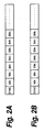
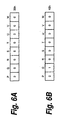
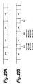
- a special pattern is a pattern of which sub code data "00h (where h represents hexadecimal notation)" or "40h” is followed by a data symbol "90h”, followed by data symbols "B9h” and "9Ah” that are alternately repeated in one frame.
- the main digital data supplied from the input terminal 6 and the special pattern data supplied from the input terminal 8 are supplied to a CIRC (Cross Interleave Reed-Solomon Code) encoder 17 through a switch circuit 11.
- the switch circuit 11 is switched at a predetermined timing according to an output of an area controlling circuit 16 so as to place data of the special pattern at a predetermined position of the main digital data.
- the CIRC encoder 17 performs an error correction code encoding process for adding error correction parity data or the like and a scrambling process. In other words, 16 bits of one sample or one word are divided into two symbols that are high order eight bits and low order eight bits. In the unit of one symbol, the error correction code encoding process for adding for example CIRC error correction parity data or the like and the scrambling process are performed.
- the sub code data supplied from the input terminal 7 is converted into sub code data having the EFM frame format of a sub code by a sub code encoder 10.
- An output of the CIRC encoder 17 and an output of the sub code encoder 10 are supplied to a multiplexer 13.
- the multiplexer 13 arranges data that is output from the CIRC encoder 17 and the sub code encoder 10 in a predetermined order.
- Output data of the multiplexer 13 is supplied to the EFM modulator 12.
- the EFM modulator 12 converts a symbol of eight bits into data of 14 channel bits according to the conversion table.
- a frame sync is supplied to the EFM modulator 12.
- a merging bit selecting portion 14 and a DSV controlling portion 15 are disposed.
- the merging bit selecting portion 14 and the DSV controlling portion 15 perform a merging bit selecting process according to not only the relation of an immediately preceded code symbol and a code immediately followed thereby, but also the relation of those symbols and a code symbol further immediately followed thereby that is pre-read.
- An output of the EFM modulator 12 is supplied to the optical modulator 2.
- the EFM modulator 12 generates a record signal of the CD EFM frame format.
- the record signal is supplied to the optical modulator 2.
- modulated laser light modulated by the optical modulator 2 photoresist on the glass master disc 4 is exposed.
- a developing process and an electroplating process are performed for the glass master disc 4 on which data has been recorded in such a manner.
- a metal master is produced.
- a mother disc is produced.
- a stamper is produced.
- a substrate for an optical disc is produced by the compression molding method, the injection molding method, or the like.
- a reflection layer made of Al or the like is formed on the produced disc substrate.
- a protection layer is formed.
- an optical disc is produced.
- Fig. 3 shows the data structure of one EFM frame of the CD format.
- parity Q and parity P which are four symbols each are made from a total of 12 samples (24 symbols) of two-channel digital audio data. 33 symbols (264 data bits) of which one symbol of sub code data is added to a total of 32 symbols is treated as one block.
- one frame which has been EFM modulated contains sub code data of one symbol, data of 24 symbols, a Q parity of four symbols, and a P parity of four symbols.
- each data symbol (eight data bits) is converted into a code symbol of 14 channel bits. Merging bits of three bits are placed between two code symbols of 14 channel bits each.
- a frame sync pattern is added at the beginning of a frame.
- a frame sync pattern is a pattern of which 11T, 11T, and 2T are in succession. Since such a pattern does not take place according to the EFM conversion rule, a frame sync can be detected with such a special pattern.
- the total number of bits of one EFM frame is 588 channel bits.
- the frame frequency is 7.35 kHz.
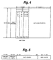
- sub code frame As shown in Fig. 4, a block of 98 EFM frames is referred to as sub code frame (or sub code frame).
- a sub code frame of which 98 frames are arranged in succession is composed of a sync pattern portion that identifies the beginning of the sub code frame, a sub code portion, and a data and parity portion.
- a sub code frame is equivalent to 1/75 second of a reproduction time of a conventional CD.
- the sub code portion is composed of 98 EFM frames. Two frames at the beginning of the sub code portion are synchronous patterns S0 and S1 of the sub code frame and patterns of an EFM out-of-rule.
- the individual bits of the sub code portion compose P, Q, R, S, T, U, V, and W channels.
- R channel to W channel may be used for special purposes such as a still picture or a subtitle display of so-called Karaoke, they are normally not used.
- P channel and Q channel are used for a track position controlling operation for the pickup during reproduction of digital data recorded on the disc.
- P channel is used to record a signal whose level is "0" in a so-called lead-in area, which is an inner peripheral portion of the disc and a signal whose level alternately varies between "0" and "1" at predetermined periods in a so-called lead-out area, which is an outer peripheral portion of the disc.
- P channel is also used to record a signal whose level is “1” between music programs in a program area formed between the lead-in area and the lead-out area of the disc and a signal whose level is "0” in the other area.
- P channel is used to detect the beginning of each music program during reproduction of digital audio data recorded on the CD.
- Q channel is provided to more acutely control digital audio data recorded on the CD during reproduction.
- One sub code frame of Q channel is composed of a control bit portion, an address bit portion, a data bit portion, and a CRC (Cyclic Redundancy Check) bit portion as shown in Fig. 5.
- a data symbol in the sub code portion is "00h” or "40h".
- R to W channels are not used, whereas P channel and Q channel are used.
- P channel is "0".
- data of Q channel is "0”
- a data symbol in the sub code portion is "00h”.
- data of Q channel is "1”
- a data symbol in the sub code portion is "40h”.
- a special pattern is placed in such a manner that merging bits selected in the EFM modulation when DSV is controlled according to the relation of an immediately preceded code symbol and a code immediately followed thereby are different from merging bits selected in the EFM modulation when DSV is controlled according to the relation of that code symbol and a code symbol further immediately followed thereby.
- the EFM modulation As described above, in the CD format, as a modulating system used to record data, the EFM modulation is used. In the EFM modulation, eight data bits (sometimes referred to as data symbol) are converted into 14 channel bits (sometimes referred to as code symbol). In addition, when 14-bit code symbols are connected, merging bits are placed therebetween so as to satisfy the run length limit conditions and keep DC balance.
- Fig. 7 to Fig. 12 show an example of the EFM conversion table that converts data bits of eight bits into channel bits of 14 bits.
- data symbols are represented in hexadecimal notation (00 to FF), decimal notation (0 to 255), and binary notation (d1 ..., d8).
- "1" of a code symbol represents that a waveform is inverted.
- the minimum time length of the EFM modulation (time length in which the number of 0s between two 1s of a record signal becomes the minimum) Tmin is 3T.
- the maximum time length of the EFM modulation time length in which the number of 0s between two 1s of a record signal becomes the maximum) Tmax is 11T.
- the pit length equivalent to T is the shortest pit length. All code symbols shown in Fig. 7 to Fig. 12 satisfy rules of which the minimum time length is 3T and the maximum time length Tmax is 11T (hereinafter they are referred to as run length limit conditions).
- merging bits there are four types of patterns "000”, “001”, “010”, and "100".
- the four patterns of merging bits one pattern that satisfies the run length limit conditions of which the minimum time length Tmin is 3T and the maximum time length is 11T and of which DSV (Digital Sum Variation) is close to "0" is selected.
- DSV is a cumulative value of which when a waveform is in a high level, "+1" is counted and when a waveform is in a low level, "-1" is counted.
- DSV at timing t0 is (-3).
- Fig. 13B shows the case that "000” are used as merging bits.
- Fig. 13C shows the case that "010” are used as merging bits.
- Fig. 13D shows the case that "001" are used as merging bits.
- DSV is "-3" at timing t0.
- DSV is "+3" in period (t0 to t1).
- DSV is "-3" at timing t0.
- DSV is "-3" at timing t0.
- DSV does not always converge to "0" in every pattern. In other words, in some special patterns, DSV does not converge to "0".
- a pattern of which data symbols "FAh” are repeated as shown in Fig. 14A is considered.
- a data symbol "FAh” is converted into a code symbol of 14 bits according to the foregoing conversion table, a code symbol (10010000010010) is obtained.
- Fig. 14C shows a waveform of the pattern shown in Fig. 14B.
- DSV negatively increases, not converges to "0".
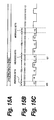
- Fig. 15C shows a waveform of the pattern shown in Fig. 15B.
- code symbols (10001000010010) of 14 channel bits each, into which data symbols "FBh” have been converted are connected with merging bits (000)
- DSV negatively increases, not converges to "0".
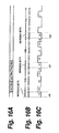
- a pattern of which data symbols "FAh” and "FBh” are alternately repeated As shown in Fig. 16A, a pattern of which data symbols "FAh” and "FBh” are alternately repeated.
- a code symbol (10010000010010) is obtained.
- a data symbol "FBh” is converted into a code symbol of 14 bits according to the foregoing conversion table, a code symbol (10001000010010) is obtained.
- Tmin 3T
- Fig. 16C shows a waveform of the pattern shown in Fig 16B.
- DSV is "-49" at timing t51.
- DSV is "-51" at timing t51.
- (000) are selected as merging bits.
- a data symbol "90h” is followed by a data symbol "B9h”.
- a code symbol "10000000001001” is obtained.
- the data symbol "B9h” is followed by a data symbol "9Ah”.
- a code symbol (10010000000001) is obtained.
- (000) are unconditionally selected.
- DSV varies by "-5" in the period of the data symbol "B9h”.
- DSV varies by "-9" in the period of the data symbol "9Ah”.
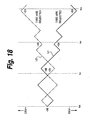
- DSV varies as denoted by broken line L1 of Fig. 18. Thereafter, since the data symbols "9Ah” and “B9h” are alternately repeated, DSV negatively increases. Thus, DSV does not converge to "0".
- Fig. 17E shows a waveform in the case that (100) are selected as the first merging bits.
- the data symbol “B9h” is followed by the data symbol "9Ah”.
- a code symbol (10010000000001) is obtained.
- (000) are unconditionally selected.
- DSV varies by "+5" in the period of the data symbol "B9h”.
- DSV varies by "+9” in the period of the data symbol "9Ah”.
- DSV varies as denoted by broken line L2 of Fig. 18.
- the data symbol "9Ah” and the data symbol “B9h” are alternately repeated.
- DSV positively increases.
- DSV converges to "0".
- merging bits of which DSV approaches to "0" according to the relation of an immediately preceded code symbol and a code symbol immediately followed thereby are different from merging bits of which DSV approaches to "0" according to the relation of that code symbol and a code symbol further immediately followed thereby.
- the predetermined number A is normally "1".
- the EFM modulator 12, the merging bit selecting portion 14, and the DSV controlling portion 15 select merging bits according to not only the relation of an immediately preceded code symbol and a code symbol immediately followed thereby, but also the relation of that code symbol and a code symbol further immediately followed thereby that is pre-read.
- merging bits are selected so that DSV converges to "0".
- the EFM modulating portion selects merging bits of which DSV approaches to "0" according to the relation of only an immediately preceded code symbol and a code symbol immediately followed thereby not the relation of that code symbol and a code symbol further immediately followed thereby that is pre-read.
- a special pattern shown in Fig. 2A, Fig. 2B, or Fig. 17A to Fig. 17E is reproduced from a copied recording medium, since DSV increases, the reproducing operation cannot be performed.
- Fig. 19 is a flow chart showing an example of a process for selecting merging bits according to not only the relation of an immediately preceded code symbol and a code symbol immediately followed thereby, but also the relation of that code symbol and a code symbol further immediately followed thereby that is pre-read as with the EFM modulator 12, the merging bit selecting portion 14, and the DSV controlling portion 15 of the mastering apparatus shown in Fig. 1.
- these data symbols D0, D1, D2, D3, D4, ... and so forth are converted into code symbols of 14 bits each.
- the converted code symbols are denoted by d0, d1, d2, d3, ..., and so forth.
- n (1) is incremented (at step S7).
- n (2) is incremented (at step S7).
- the data symbols D3, D4, .... and so forth may be pre-read.
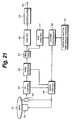
- Fig. 21 shows an example of the structure of a reproducing apparatus that reproduces data from an optical disc that has been produced in the foregoing mastering and stamping processes.
- reference numeral 21 represents a disc as a recording medium produced in the foregoing mastering and stamping processes.
- Reference numeral 22 represents a spindle motor that drives the rotations of the disc 21.
- Reference numeral 23 represents an optical pickup that reproduces a signal from the disc 21.
- the optical pickup 23 is composed of a semiconductor laser that radiates laser light to the disc 21, an optical system such as an objective lens, a detector that receives light reflected from the disc 21, a focus and tracking mechanism, and so forth.
- the optical pickup 23 is traveled in the radius direction of the disc 21 by a thread mechanism (not shown).
- Output signals of for example a four-divided detector of the optical pickup 23 are supplied to an RF portion 24.
- the RF portion 24 calculates the output signals of the individual detector elements of the four-divided detector and generates a reproduction (RF) signal, a focus error signal, and a tracking error signal.
- the reproduction signal is supplied to a sync detecting portion 25.
- the sync detecting portion 25 detects a frame sync from the beginning of each EFM frame.
- the detected frame sync, the focus error signal, and the tracking error signal are supplied to a servo portion 26.
- the servo portion 26 controls the rotations of the spindle motor 22 and performs a focus servo and a tracking servo of the optical pickup 23 corresponding to a reproduced clock of the RF signal.
- Main data that is output from the sync detecting portion 25 is supplied to an EFM demodulator 27.
- the EFM demodulator 27 performs an EFM demodulating process for the main data.
- Main digital data is supplied from the EFM demodulator 27 to a CIRC decoder 28.
- the CIRC decoder 28 performs an error correcting process for the main digital data.
- An interpolating circuit 29 interpolates the main digital data and outputs the interpolated data as reproduced data to an output terminal 30.
- Sub code data is supplied from the EFM demodulator 27 to a system controller 32.
- the system controller 32 is composed of a microcomputer.
- the system controller 32 controls operations of the whole reproducing apparatus.
- an operation button and display portion 33 is disposed.
- the system controller 32 controls the servo portion 26 so as to access a desired position of the digital 21.
- a special pattern of which merging bits selected in the EFM modulation when DSV is controlled according to the relation of an immediately preceded code symbol and a code symbol immediately followed thereby are different from merging bits selected in the EFM modulation when DSV is controlled according to the relation of that code symbol and a code symbol further immediately followed thereby is recorded on the disc 21.
- the EFM modulator 12 of the master apparatus shown in Fig. 1 has the merging bit selecting portion 14 and the DSV controlling portion 15. As shown in Fig.
- the merging bit selecting portion 14 and the DSV controlling portion 15 perform the merging bit selecting process according to not only the relation of an immediately preceded code symbol and a code symbol immediately followed thereby, but also'the relation of those code symbol and a code symbol further immediately followed thereby that is pre-read.
- merging bits are added so that DSV finally converges to "0".
- the special pattern portion can be reproduced.
- a conventional CD-R disc recording apparatus selects merging bits of which DSV approaches to "0" in the EFM modulation according to the relation of an immediately preceded code symbol and a code symbol immediately followed thereby.
- DSV does not converge to "0".
- the DC balance is lost and the reproducing operation cannot be performed. Consequently, the copying operation can be prevented.
- Fig. 22 is a flow chart showing a merging bit controlling process performed by a conventional EFM modulator disposed in a CD-R disc drive and a CD-RW disc drive.
- an immediately preceded data symbol is denoted by D0
- a data symbol of eight bits immediately followed thereby is denoted by D1
- a data symbol of eight bits further immediately followed thereby is denoted by D2
- other data symbols further immediately followed thereby are denoted by D3, D4, ... and so forth.
- these code symbols D0, D1, D2, D3, D4, ... and so forth are converted into code symbols of 14 bits. These converted code symbols are denoted by d1, d2, d3, ... and so forth.
- the data symbol D1 of eight bits is input (at step S51).
- the data symbol D1 is converted into the code symbol d1 of 14 bits according to the conversion table (at step S52). Thereafter, merging bits placed between the current code symbol d1 and the code symbol d0 immediately preceded thereby are selected (at step S53).
- n is incremented (at step S57).
- n advances from “0" to "3".
- Information of merging bits that satisfy the run length limit conditions is stored at step 558.
- DSV is calculated.
- DSV is obtained.
- the minimum value of absolute values of DSV is selected (at step S60).
- merging bits placed between the code symbol d0 and the code symbol d1 are decided (at step S61).
- merging bits placed between the code symbol d0 and the code symbol d1 are selected according to only the relation of the immediately preceded code symbol d0 and the current code symbol d1.
- a special pattern shown in Fig. 2A, Fig. 2B, or Fig. 17A to Fig. 17E is contained, since DSV increases, the reproducing operation cannot be performed.
- Fig. 24 shows an outline of a flow of a copying process.
- a reproducing apparatus denoted by reference numeral 41 reproduces data from an original disc.
- the disc 21 is a CD format disc.
- a special pattern is contained at a predetermined position in such a manner that merging bits selected in the EFM modulation when DSV is controlled according to the relation of an immediately preceded code symbol and a code symbol immediately followed thereby are different from merging bits selected in the EFM modulation when DSV is controlled according to that code symbol and a code symbol further immediately followed thereby.
- Reference numeral 43 represents an optical pickup.
- Reference numeral 44 represents a reproduction signal process portion. Reproduced data is supplied from the reproducing apparatus 41 to a recording process portion 52 of a recording apparatus 51.
- An optical pickup 53 records the reproduced data to a disc 54, for example a CD-R disc.
- the recorded contents of the original disc 21 are copied to the CD-R disc 54.
- the reproducing apparatus 41 and the recording apparatus 51 can use a recording and reproducing apparatus structured as a CD-R disc drive or a CD-RW disc drive.
- a sync detecting portion 46 of the reproducing process portion 44 detects a frame sync from a reproduced signal supplied from an input terminal 45.
- An EFM demodulator 47 EFM-demodulates the reproduced signal and supplies the EFM-demodulated reproduced data to a CIRC decoder 48.
- the CIRC decoder 48 corrects an error of the reproduced signal.
- a special pattern shown in Fig. 2A, Fig. 2B, or Fig. 17A to Fig. 17E is contained at a predetermined position of the original disc 21 in such a manner that merging bits selected in the EFM modulation when DSV is controlled according to the relation of an immediately preceded code symbol and a code symbol immediately followed thereby are different from merging bits selected in the EFM modulation when DSV is controlled according to the relation of that code symbol and a code symbol further immediately followed thereby.
- the EFM modulator 12 of the mastering apparatus shown in Fig. 1 has the merging bit selecting portion 14 and the DSV controlling portion 15.
- the merging bit selecting portion 14 and the DSV controlling portion 15 perform the process for selecting merging bits according to not only the relation of an immediately preceded code symbol and a code symbol immediately followed thereby, but also the relation of that code symbol and a code symbol further immediately followed thereby that is pre-read.
- merging bits are added so that DSV finally converges to "0".
- the special pattern portion can be reproduced.
- Fig. 26 shows an outline of the structure of a recording process portion 52.
- Data to be recorded is supplied from an input terminal 55 to a CIRC encoder 56.
- the CIRC encoder 56 performs a CIRC encoding process for the data to be recorded.
- Sub code data is supplied from an input terminal 57 to a sub code encoder 58.
- the sub code encoder 58 formats the sub code.
- An output of the CIRC encoder 56 and an output of the sub code encoder 58 are supplied to a multiplexer 60.
- a frame sync is supplied from an input terminal 59 to the multiplexer 60.
- the multiplexer 60 arranges those data in a predetermined order.
- An output of the multiplexer 60 is supplied to an EFM modulator 61.
- the EFM modulator 61 performs an EFM modulating process for data that is output from the multiplexer 60.
- the EFM modulator 61 normally selects merging bits of which DSV approaches to "0" according to the relation of an immediately preceded code symbol and a code symbol immediately followed thereby.
- a reproduction signal of a portion of a special pattern at a predetermined position is sent to the EFM modulator 61, merging bits of which DSV approaches to "0" according to the relation of an immediately preceded code symbol and a code symbol immediately followed thereby are selected.
- DSV increases.
- the signal is recoded on a copy disc 54 such as a CD-R disc.
- the process for selecting merging bits according to not only the relation of an immediately preceded code symbol and a code symbol immediately followed thereby, but also the relation of that code symbol and a code symbol further immediately followed thereby that is pre-read is performed.
- merging bits may be added so that merging bits added to the special pattern are different from merging bits added to the other portion.
- the EFM modulator 12 a conventional modulator that selects merging bits of which DSV approaches to "0" according to the relation of an immediately preceded code symbol and a code symbol immediately followed thereby can be used.
- the permission and prohibition of the use of contents other than the special pattern portion can be controlled.
- the data pattern portion can be reproduced.
- the special pattern portion cannot be reproduced.
- the disc is detected as an original disc or a copy thereof. According to the detected result, it is determined whether or not contents recorded in other than the data pattern portion can be used. As a result, contents of a copied disc can be prohibited from being used.
- the special pattern would be placed in a key data portion of encrypted contents. From a copied disc, the key data portion would be prohibited from being reproduced.
- the present invention can be applied to EFM Plus.
- the EFM Plus is a system that converts a data symbol of eight bits into a code symbol of 16 bits without need to use merging bits.
- DSV can be prevented from increasing.
- it can be determined whether or not a disc to be used is an original disc of which data was recorded using an encoder according to the present invention or a copied disc of which data was recorded using a conventional encoder.
- the present invention can be also applied to a multi-session optical disc on which for example CD-DA formatted data and CD-ROM formatted data are recorded.
- information that is recorded to an optical disc there are various types of data such as audio data, video data, still picture data, character data, computer graphic data, game software, and computer programs.
- the present invention can be applied to for example a DVD video disc and a DVD-ROM disc.
- the present invention can be applied to not only a disc-shaped data recording medium, but also a card-shaped data recording medium.
- an original disc is produced by the mastering apparatus.
- an original disc may be produced with a CD-R disc or a CD-RW disc.
- a special pattern is recorded, since it does not require to physically deform a disc with for example pits, even if an original disc is a recording medium using wobble pits such as a CD-R disc or a CD-RW disc, a copy can be protected.
- a special pattern is recorded on a recording medium in such a manner that merging bits selected in the EFM modulation when DSV is controlled according to the relation of an immediately preceded code symbol and a code symbol immediately followed thereby are different from merging bits selected in the EFM modulation when DSV is controlled according to the relation of those code symbol and a code symbol further immediately followed thereby.
- the EFM modulating portion of the master apparatus that produces an original CD selects merging bits according to not only the relation of an immediately preceded code symbol and a code symbol immediately followed thereby, but also the relation of that code symbol and a code symbol further immediately followed thereby that is pre-read.
- a copying operation can be prohibited for not only a disc having wobble pits, but also an original recording medium that is a CR-R or CD-RW.
- the present invention since a defect is not intentionally placed on an original medium, the present invention can be used as a format standard.
Landscapes
- Engineering & Computer Science (AREA)
- Signal Processing (AREA)
- Theoretical Computer Science (AREA)
- Computer Security & Cryptography (AREA)
- Signal Processing For Digital Recording And Reproducing (AREA)
- Optical Recording Or Reproduction (AREA)
Applications Claiming Priority (3)
| Application Number | Priority Date | Filing Date | Title |
|---|---|---|---|
| JP2002138199A JP4143330B2 (ja) | 2002-05-14 | 2002-05-14 | データ記録媒体、データ記録方法及び装置 |
| JP2002138199 | 2002-05-14 | ||
| PCT/JP2003/005876 WO2003096344A1 (fr) | 2002-05-14 | 2003-05-12 | Support d'enregistrement de donnees, procede et dispositif d'enregistrement de donnees et procede et dispositif de codage |
Publications (2)
| Publication Number | Publication Date |
|---|---|
| EP1505598A1 true EP1505598A1 (fr) | 2005-02-09 |
| EP1505598A4 EP1505598A4 (fr) | 2009-09-16 |
Family
ID=29416844
Family Applications (1)
| Application Number | Title | Priority Date | Filing Date |
|---|---|---|---|
| EP03725773A Withdrawn EP1505598A4 (fr) | 2002-05-14 | 2003-05-12 | Support d'enregistrement de donnees, procede et dispositif d'enregistrement de donnees et procede et dispositif de codage |
Country Status (7)
| Country | Link |
|---|---|
| US (1) | US7289046B2 (fr) |
| EP (1) | EP1505598A4 (fr) |
| JP (1) | JP4143330B2 (fr) |
| KR (1) | KR20040108529A (fr) |
| CN (1) | CN1311464C (fr) |
| TW (1) | TWI240251B (fr) |
| WO (1) | WO2003096344A1 (fr) |
Cited By (7)
| Publication number | Priority date | Publication date | Assignee | Title |
|---|---|---|---|---|
| US5899481A (en) * | 1995-09-06 | 1999-05-04 | Idit International Design N.V. | Telescopic element, particularly for frames of folding bicycles |
| GB2398670B (en) * | 2003-02-21 | 2006-02-08 | Macrovision Europ Ltd | Copy protection for applications |
| GB2398671B (en) * | 2003-02-21 | 2007-06-06 | Macrovision Europ Ltd | The transmission of information |
| US7464411B2 (en) | 2000-07-28 | 2008-12-09 | Macrovision Corporation | Copy protection for optical discs |
| US7539394B2 (en) | 2003-01-24 | 2009-05-26 | Macrovision Europe Limited | Method and apparatus for the copy protection of optical discs |
| US7701825B2 (en) | 2005-06-17 | 2010-04-20 | Macrovision Corporation | Apparatus for and a method of authenticating recording media |
| US7788504B2 (en) | 2004-05-19 | 2010-08-31 | Rovi Solutions Corporation | Copy protection of optical discs |
Families Citing this family (3)
| Publication number | Priority date | Publication date | Assignee | Title |
|---|---|---|---|---|
| JP3971635B2 (ja) * | 2002-04-08 | 2007-09-05 | 株式会社ソニー・ディスクアンドデジタルソリューションズ | データ記録媒体、データ記録方法および装置 |
| EP2183922A4 (fr) * | 2007-08-16 | 2011-04-27 | Nokia Corp | Procédé et appareils de codage et de décodage d'une image |
| US9420511B2 (en) | 2012-11-01 | 2016-08-16 | Intel Corporation | Signaling QoS requirements and UE power preference in LTE-A networks |
Family Cites Families (11)
| Publication number | Priority date | Publication date | Assignee | Title |
|---|---|---|---|---|
| JP2656024B2 (ja) * | 1986-05-29 | 1997-09-24 | 松下電器産業株式会社 | 変調回路 |
| JP3387105B2 (ja) * | 1991-09-30 | 2003-03-17 | ソニー株式会社 | 変調回路 |
| US5349349A (en) * | 1991-09-30 | 1994-09-20 | Sony Corporation | Modulator circuit for a recording for a digital recording medium |
| US5349350A (en) * | 1991-10-31 | 1994-09-20 | Integral Peripherals, Inc. | Run length limited encoding/decoding system for low power disk drives |
| JPH07245565A (ja) * | 1994-03-02 | 1995-09-19 | Sony Corp | 信号変調方法及び信号変調回路 |
| PL183099B1 (pl) * | 1995-09-01 | 2002-05-31 | Koninkl Philips Electronics Nv | Sposób konwersji ciągu m-bitowych słów informacji do postaci sygnału modulowanego, urządzenie kodujące i nośnik zapisu |
| US5699434A (en) * | 1995-12-12 | 1997-12-16 | Hewlett-Packard Company | Method of inhibiting copying of digital data |
| TW538372B (en) * | 1999-10-02 | 2003-06-21 | Mediatek Inc | Zero digital sum value control device and method |
| RU2280906C2 (ru) * | 2000-07-28 | 2006-07-27 | Макровижн Юроп Лимитед | Защита от копирования для оптических дисков |
| MXPA02009474A (es) * | 2001-02-02 | 2003-09-22 | Koninkl Philips Electronics Nv | METODO PARA CONVERTIR UNA SERIE DE PALABRAS DE INFORMACION M-BIT EN UNA SEnAL MODULADA. |
| KR100669623B1 (ko) * | 2001-03-12 | 2007-01-15 | 엘지전자 주식회사 | 디지털 데이터 변환방법 |
-
2002
- 2002-05-14 JP JP2002138199A patent/JP4143330B2/ja not_active Expired - Fee Related
-
2003
- 2003-05-12 KR KR10-2003-7016083A patent/KR20040108529A/ko not_active Ceased
- 2003-05-12 EP EP03725773A patent/EP1505598A4/fr not_active Withdrawn
- 2003-05-12 US US10/483,622 patent/US7289046B2/en not_active Expired - Fee Related
- 2003-05-12 CN CNB038006588A patent/CN1311464C/zh not_active Expired - Fee Related
- 2003-05-12 WO PCT/JP2003/005876 patent/WO2003096344A1/fr not_active Ceased
- 2003-05-14 TW TW092113091A patent/TWI240251B/zh not_active IP Right Cessation
Cited By (10)
| Publication number | Priority date | Publication date | Assignee | Title |
|---|---|---|---|---|
| US5899481A (en) * | 1995-09-06 | 1999-05-04 | Idit International Design N.V. | Telescopic element, particularly for frames of folding bicycles |
| US7464411B2 (en) | 2000-07-28 | 2008-12-09 | Macrovision Corporation | Copy protection for optical discs |
| US7661145B2 (en) | 2001-07-26 | 2010-02-09 | Macrovision Europe Limited | Method and apparatus for copy protection for applications |
| US7539394B2 (en) | 2003-01-24 | 2009-05-26 | Macrovision Europe Limited | Method and apparatus for the copy protection of optical discs |
| US8260115B2 (en) | 2003-01-24 | 2012-09-04 | Rovi Europe Limited | Method and product for copy protection of optical discs using unbalanced DC content |
| GB2398670B (en) * | 2003-02-21 | 2006-02-08 | Macrovision Europ Ltd | Copy protection for applications |
| GB2398671B (en) * | 2003-02-21 | 2007-06-06 | Macrovision Europ Ltd | The transmission of information |
| US7334268B2 (en) | 2003-02-21 | 2008-02-19 | Macrovision Europe Limited | Method and apparatus for data files used in the transmission of information |
| US7788504B2 (en) | 2004-05-19 | 2010-08-31 | Rovi Solutions Corporation | Copy protection of optical discs |
| US7701825B2 (en) | 2005-06-17 | 2010-04-20 | Macrovision Corporation | Apparatus for and a method of authenticating recording media |
Also Published As
| Publication number | Publication date |
|---|---|
| WO2003096344A1 (fr) | 2003-11-20 |
| JP4143330B2 (ja) | 2008-09-03 |
| CN1533573A (zh) | 2004-09-29 |
| JP2003331534A (ja) | 2003-11-21 |
| CN1311464C (zh) | 2007-04-18 |
| TW200407855A (en) | 2004-05-16 |
| EP1505598A4 (fr) | 2009-09-16 |
| US20050117491A1 (en) | 2005-06-02 |
| TWI240251B (en) | 2005-09-21 |
| US7289046B2 (en) | 2007-10-30 |
| KR20040108529A (ko) | 2004-12-24 |
Similar Documents
| Publication | Publication Date | Title |
|---|---|---|
| US7030788B2 (en) | Data recording medium, data recording method, and apparatus | |
| US7289046B2 (en) | Data recording medium, data recording method and device, and encode method and device | |
| US7304932B2 (en) | Data recording medium, and data recording method and device | |
| US7366071B2 (en) | Data recording method and device, data recording medium, data reproduction method and device | |
| US7215260B2 (en) | Data recording medium, data recording method, and device | |
| US7272098B2 (en) | Data recording apparatus and associated methodology of affecting a digital sum variance | |
| US7098820B2 (en) | Data recording method | |
| EP1526532A1 (fr) | Procede et dispositif d'enregistrement de donnees | |
| KR20050016277A (ko) | 데이터 기록 매체, 데이터 기록 방법 및 장치 | |
| HK1073013B (en) | Data recording method | |
| JP2004152371A (ja) | オーディオデータ加工方法、プログラム、記録媒体およびオーディオデータ |
Legal Events
| Date | Code | Title | Description |
|---|---|---|---|
| PUAI | Public reference made under article 153(3) epc to a published international application that has entered the european phase |
Free format text: ORIGINAL CODE: 0009012 |
|
| 17P | Request for examination filed |
Effective date: 20040114 |
|
| AK | Designated contracting states |
Kind code of ref document: A1 Designated state(s): AT BE BG CH CY CZ DE DK EE ES FI FR GB GR HU IE IT LI LU MC NL PT RO SE SI SK TR |
|
| AX | Request for extension of the european patent |
Extension state: AL LT LV MK |
|
| DAX | Request for extension of the european patent (deleted) | ||
| RBV | Designated contracting states (corrected) |
Designated state(s): AT BE BG DE GB |
|
| RAP1 | Party data changed (applicant data changed or rights of an application transferred) |
Owner name: SONY DISC AND DIGITAL SOLUTIONS INC. Owner name: SONY CORPORATION |
|
| A4 | Supplementary search report drawn up and despatched |
Effective date: 20090814 |
|
| RIC1 | Information provided on ipc code assigned before grant |
Ipc: H03M 7/46 20060101ALI20090810BHEP Ipc: H03M 5/14 20060101ALI20090810BHEP Ipc: G11B 20/14 20060101ALI20090810BHEP Ipc: G11B 20/00 20060101AFI20090810BHEP |
|
| STAA | Information on the status of an ep patent application or granted ep patent |
Free format text: STATUS: THE APPLICATION HAS BEEN WITHDRAWN |
|
| 18W | Application withdrawn |
Effective date: 20100601 |