EP1506832B1 - Verfahren und Vorrichtung zur drehenden Rührformung - Google Patents
Verfahren und Vorrichtung zur drehenden Rührformung Download PDFInfo
- Publication number
- EP1506832B1 EP1506832B1 EP04077223A EP04077223A EP1506832B1 EP 1506832 B1 EP1506832 B1 EP 1506832B1 EP 04077223 A EP04077223 A EP 04077223A EP 04077223 A EP04077223 A EP 04077223A EP 1506832 B1 EP1506832 B1 EP 1506832B1
- Authority
- EP
- European Patent Office
- Prior art keywords
- workpiece
- shoulder
- pin
- tool
- friction stir
- Prior art date
- Legal status (The legal status is an assumption and is not a legal conclusion. Google has not performed a legal analysis and makes no representation as to the accuracy of the status listed.)
- Expired - Lifetime
Links
Images



Classifications
-
- B—PERFORMING OPERATIONS; TRANSPORTING
- B23—MACHINE TOOLS; METAL-WORKING NOT OTHERWISE PROVIDED FOR
- B23K—SOLDERING OR UNSOLDERING; WELDING; CLADDING OR PLATING BY SOLDERING OR WELDING; CUTTING BY APPLYING HEAT LOCALLY, e.g. FLAME CUTTING; WORKING BY LASER BEAM
- B23K20/00—Non-electric welding by applying impact or other pressure, with or without the application of heat, e.g. cladding or plating
- B23K20/12—Non-electric welding by applying impact or other pressure, with or without the application of heat, e.g. cladding or plating the heat being generated by friction; Friction welding
-
- B—PERFORMING OPERATIONS; TRANSPORTING
- B23—MACHINE TOOLS; METAL-WORKING NOT OTHERWISE PROVIDED FOR
- B23K—SOLDERING OR UNSOLDERING; WELDING; CLADDING OR PLATING BY SOLDERING OR WELDING; CUTTING BY APPLYING HEAT LOCALLY, e.g. FLAME CUTTING; WORKING BY LASER BEAM
- B23K20/00—Non-electric welding by applying impact or other pressure, with or without the application of heat, e.g. cladding or plating
- B23K20/12—Non-electric welding by applying impact or other pressure, with or without the application of heat, e.g. cladding or plating the heat being generated by friction; Friction welding
- B23K20/122—Non-electric welding by applying impact or other pressure, with or without the application of heat, e.g. cladding or plating the heat being generated by friction; Friction welding using a non-consumable tool, e.g. friction stir welding
- B23K20/1245—Non-electric welding by applying impact or other pressure, with or without the application of heat, e.g. cladding or plating the heat being generated by friction; Friction welding using a non-consumable tool, e.g. friction stir welding characterised by the apparatus
- B23K20/126—Workpiece support, i.e. backing or clamping
-
- B—PERFORMING OPERATIONS; TRANSPORTING
- B21—MECHANICAL METAL-WORKING WITHOUT ESSENTIALLY REMOVING MATERIAL; PUNCHING METAL
- B21D—WORKING OR PROCESSING OF SHEET METAL OR METAL TUBES, RODS OR PROFILES WITHOUT ESSENTIALLY REMOVING MATERIAL; PUNCHING METAL
- B21D22/00—Shaping without cutting, by stamping, spinning, or deep-drawing
- B21D22/14—Spinning
- B21D22/16—Spinning over shaping mandrels or formers
-
- B—PERFORMING OPERATIONS; TRANSPORTING
- B21—MECHANICAL METAL-WORKING WITHOUT ESSENTIALLY REMOVING MATERIAL; PUNCHING METAL
- B21D—WORKING OR PROCESSING OF SHEET METAL OR METAL TUBES, RODS OR PROFILES WITHOUT ESSENTIALLY REMOVING MATERIAL; PUNCHING METAL
- B21D5/00—Bending sheet metal along straight lines, e.g. to form simple curves
-
- B—PERFORMING OPERATIONS; TRANSPORTING
- B23—MACHINE TOOLS; METAL-WORKING NOT OTHERWISE PROVIDED FOR
- B23K—SOLDERING OR UNSOLDERING; WELDING; CLADDING OR PLATING BY SOLDERING OR WELDING; CUTTING BY APPLYING HEAT LOCALLY, e.g. FLAME CUTTING; WORKING BY LASER BEAM
- B23K20/00—Non-electric welding by applying impact or other pressure, with or without the application of heat, e.g. cladding or plating
- B23K20/12—Non-electric welding by applying impact or other pressure, with or without the application of heat, e.g. cladding or plating the heat being generated by friction; Friction welding
- B23K20/122—Non-electric welding by applying impact or other pressure, with or without the application of heat, e.g. cladding or plating the heat being generated by friction; Friction welding using a non-consumable tool, e.g. friction stir welding
- B23K20/1275—Non-electric welding by applying impact or other pressure, with or without the application of heat, e.g. cladding or plating the heat being generated by friction; Friction welding using a non-consumable tool, e.g. friction stir welding involving metallurgical change
Definitions
- the present invention relates to the forming of structural members and, more particularly, to the forming of structural members in conjunction with friction stir processing.
- the forming of structural members to desired shapes can be accomplished by forging, stamping, bending, machining, and the like.
- a preform or blank comprising a flat sheet of metal such as steel, aluminum, titanium, or alloys thereof can be heated in a forge and hammered to the desired shape of the member.
- a mechanical or hydraulic press can be used to stamp or forge the structural member to the desired shape, e.g., between two opposing dies that define forming surfaces that correspond to the desired contour of the member.
- Such forming methods are typically quicker and less expensive than casting molten material in the desired shape, and complex shapes can be imparted to the member, such as curves, angles, and the like.
- cracks or weakened portions may result from excessive forming, e.g., the formation of sharp angles or other significant deformations. Therefore, the formation of a particular complex structural member may require that multiple elementary members are formed and then joined by welding or other joining methods. Further, subsequent material processing, e.g., heat treatments such as solution heat treating, aging, and quenching, may be required to achieve desired properties in the formed member. These additional operations add to the manufacturing time and cost of the structural members.
- the structural members can also be treated before being formed to the desired shape.
- a preform is supported in a flat configuration, and a friction stir welding tool is inserted into the preform and rotated to plasticize the material of the preform.
- the friction stir-welding tool is then moved continuously over the surface of the preform so that part of the preform is friction stir processed.
- the preform is then formed, for example, by forging, stamping, bending, or the like, to the desired shape of the member.
- Such friction stir processing refines the granular structure of the preform, improving the material properties of the structural member.
- this process is also time-consuming and adds to the cost of the structural member.
- the process should be capable of forming various configurations of structural members, including those with complex geometric configurations. Further, the process should result in structural members having desired material properties.
- the present invention provides an apparatus and method for forming a workpiece to a desired, non-planar configuration with at least one friction stir forming tool.
- the forming tool plasticizes a portion of the workpiece and urges the workpiece to the desired configuration, thereby refining the grain structure of the workpiece.
- the workpiece can be formed to any desired configuration, including complex shapes.
- the material properties of the workpiece can be improved.
- the apparatus includes a die defining a contour surface such as a dome shape that corresponds to the desired configuration of the workpiece.
- the die can also define a detail feature corresponding to a feature that is to be formed on the workpiece.
- a friction stir forming tool including a shoulder and a rotatable pin extending therefrom, is configured to urge the shoulder and pin toward the contour surface of the die.
- the shoulder urges the workpiece against the die and to the desired configuration, and the pin at least partially penetrates the workpiece and rotates to form a friction stir formed region defined by a refined granular structure.
- the apparatus also includes an actuator for adjusting the friction stir forming tool along a predefined path corresponding to the contour surface of the die, e.g., in at least two linear directions and about at least two axes of rotation.
- the die can also be rotated relative to the forming tool.
- the apparatus includes first and second friction stir forming tools in an opposing configuration so that the shoulders are directed generally inward to receive a workpiece therebetween.
- the forming tools are adjusted by one or more actuators in an inward direction against opposite sides of the workpiece so that the pins at least partially penetrate the workpiece.
- the pins are rotated to form a friction stir formed region in the workpiece, and the actuator adjusts the friction stir forming tools along a predefined path corresponding to the desired, non-planar configuration of the workpiece so that the shoulders urge the workpiece to the desired configuration.
- the present invention also provides a method for forming a workpiece.
- the workpiece is supported at least partially against the die, and the shoulder of the forming tool is urged against the workpiece.
- the pin at least partially penetrates the workpiece and the workpiece is bent against the contour surface.
- the pin of the tool is rotated in the workpiece to plasticize a portion of the workpiece, thereby forming a friction stir formed region having a refined grain structure.
- the tool is adjusted in a predefined path that corresponds to the contour surface of the die so that the shoulder urges the workpiece to the desired, non-planar configuration.
- An entire surface of the workpiece can be plasticized, thereby refining the grain structure of the workpiece over the surface.
- two or more structural members can be provided and joined to form the workpiece.
- a method includes forming the workpiece by first and second friction stir forming tools, which are configured in an opposing configuration so that the shoulders are directed generally inward toward the workpiece supported therebetween.
- the shoulders of the first and second tools are urged against the respective sides of the workpiece, and the pins of the first and second tools at least partially penetrate the respective sides.
- the pins are rotated to plasticize opposite portions of the workpiece, thereby forming opposite friction stir formed regions having refined grain structure in the workpiece.
- the tools are also adjusted in corresponding predefined paths so that the shoulders urge the workpiece to the desired, non-planar configuration.
- the workpieces 100 can be formed of metal, such as steel, aluminum, titanium, or alloys thereof, polymers, and other materials that are compatible with friction stir processing.
- the workpieces 100 can be used for a variety of applications including, but not limited to, structural panels, brackets, tubes, caps, and the like.
- a dome-shaped workpiece 100 and a tubular workpiece 110 can be formed and joined to create a closed or partially closed vessel.
- the workpieces 100 can be used as structural members for vehicles for the aerospace, aeronautical, marine, and automobile industries, or for other structures such as pressure vessels, weaponry, and the like.
- the apparatus 10 includes a die 20 , which defines a contour surface 22 that corresponds to the desired, non-planar configuration of the workpiece 100 .
- the contour surface 22 of the die 20 shown in Figure 1 is dome-shaped, but the contour surface 22 can alternatively define other shapes including complex curves, angles, and the like.
- the contour surface 22 is non-planar, i.e., the surface 22 defines one or more curves, angles, or other non-planar features.
- a non-planar surface can be defined by two or more planar portions that are disposed at an angle.
- a non-planar surface can also be formed by disposing ridges, channels, or other features on a planar die.
- the die 20 is secured to a base 30 or frame, which can be configured to rotate or otherwise move the die 20 .
- the die 20 partially receives the workpiece 100 , e.g., so that the workpiece 100 is in contact with a portion of the contour surface 22 .
- a bolt 24 or other connection device can be used to secure the workpiece 100 to the contour surface 22 of the die 20 .
- the apparatus 10 also includes a friction stir forming tool 40 with a shoulder 42 and a pin 44 .
- An actuator 50 is configured to rotate the tool 40 and adjust the tool 40 relative to the die 20 and the workpiece 100 .
- the actuator 50 can advance the rotating tool 40 toward the workpiece 100 and at least partially penetrate a first side 102 of the workpiece 100 with the pin 44 .
- the actuator 50 is also configured to adjust the tool 40 along a predetermined path so that the rotating pin 44 is moved through the workpiece 100 .
- the actuator 50 can be connected to a linkage or frame 52 that supports and/or moves the actuator 50 .
- the actuator 50 and/or the frame 52 can be a computer numeric controlled (CNC) device, which can be programmable, as conventionally used for controlling a machining head.
- CNC computer numeric controlled
- the pin 44 frictionally heats and plasticizes a region of the workpiece 100 .
- the plasticized region then cools and hardens to form a friction stir formed region 114 having a refined granular structure, as shown in Figure 2 .
- the effect on the material properties of the workpiece 100 that results from the friction stir processing operation of the present invention is similar to or the same as that which results from friction stir welding, as described in U.S. Patent No.
- the friction stir forming tool 40 and/or the die 20 can be adjustable to move the tool 40 through the workpiece 100 .
- the die 20 is connected to the base 30 via a rotation device 32 that is configured to rotate the die 20 and the workpiece 100 relative to the base 30 , either manually or by an actuator (not shown).
- the friction stir forming tool 40 is configured to be adjusted by the actuator 50 through an arc corresponding to the contour of the die 20 , as indicated in Figure 2 . That is, the tool 40 is moved through a curved path and rotated about an axis perpendicular to the longitudinal direction of the pin 44 , so that the pin 44 is moved through the workpiece 100 .
- the friction stir forming tool 40 and the die 20 can be adjusted so that the pin 44 is moved through the entire surface 102 of the workpiece 100 .
- the friction stir forming tool 40 can be adjusted radially outward from the center of the workpiece 100 toward an edge of the workpiece 100 while the die 20 is rotated, thereby adjusting the pin 44 through a spiraling path through the workpiece 100 .
- the friction stir forming tool 40 and the die 20 can move in other manners relative to one another.
- the die 20 can be held stationary while the forming tool 40 is moved throughout the surface 102 of the workpiece 100 , and the forming tool 40 can be rotated about multiple axes so that the shoulder 42 is kept substantially parallel to the contour surface 22 of the die 20 and/or the surface 102 of the workpiece 100 .
- the pin 44 can be perpendicular to the shoulder 42 so that the pin 44 is kept substantially perpendicular to the surface of the workpiece 100 as the shoulder 42 is urged thereagainst, i.e., the pin 44 is perpendicular to a plane tangential to the contour surface 22 at a point collinear with the pin 44 .
- the pin 44 can be long enough to extend through the entire thickness of the workpiece 100 .
- the pin 44 can be shorter than the thickness of the workpiece 100 , for example, about half the thickness of the workpiece 100 .
- the pin 44 can be adjustable relative to the shoulder 42 so that the pin 44 can be extended, as shown in Figure 2 , and retracted, as shown in Figure 1 .
- the tool 40 can be used to process workpieces 100 of different thicknesses.
- the pin 44 can be adjusted during processing of the workpiece 100 so that the pin 44 can penetrate different portions of the workpiece 100 at different depths.
- the pin 44 can be extended while processing the thicker portions of the workpiece 100 and retracted while processing the thinner portions of the workpiece 100 .
- the pin 44 can also be extended from the shoulder 42 and into the workpiece 100 during the start of each processing operation and/or retracted from the shoulder 42 and, hence, from the workpiece 100 at the end of each processing operation.
- the shoulder 42 is urged against the workpiece 100 and urges the workpiece 100 toward the contour surface 22 and to the desired configuration or the workpiece 100 .
- the workpiece 100 can begin in a flat configuration and can be bent or otherwise formed to the desired shape, as illustrated in Figure 2 .
- the shoulder 42 can urge the plasticized material from the processed portions of the workpiece 100 , thereby forming nonuniformities in the workpiece 100 , or forming a uniform workpiece 100 that is thinner throughout.
- the predetermined path can pass through the entire surface 102 of the workpiece 100 , i.e., so that the granular structure of substantially the entire surface 102 is refined.
- the pin 44 can be passed through only select portions of the workpiece 100 , for example, at incrementally spaced locations or at particular portions where grain refinement is desired in the workpiece 100 .
- detail features 26 such as grooves, ridges, apertures, knobs, and the like can be provided on the contour surface 22 so that, as the workpiece 100 is formed against the die 20 , a corresponding detail is formed in the workpiece 100 .
- the detail feature 26 shown in Figures 1 and 2 is a groove extending circumferentially around the die 20, which causes a corresponding ridge to be formed in the workpiece 100 .
- a forming apparatus 10a according to the present invention can also be used to join the workpiece 100 to another member 110 .
- the die 20 defines a dome-shaped contour similar to the one shown in Figure 1 .
- an extension 28 is disposed between the base 30 and the die 20 so that an additional member 110 , such as a tube, can be disposed proximate to the workpiece 100 .
- the tube 110 is supported by a support member 34 such that the tube 110 is positioned adjacent the workpiece 100 when the workpiece 100 is formed to the desired configuration so that an interface 112 is defined therebetween.
- Clamping members 36 can also be provided for securing the tube 110 to the support member 34 .
- the tube 110 and the die 20 are supported by the rotation device 32 and are rotatable relative to the friction stir forming tool 40 .
- the pin 44 of the friction stir forming tool 40 can be inserted at the interface 112 of the workpiece 100 and the tube 110 , and the workpiece 100 and the tube 110 can be rotated by the rotation device 32 so that the pin 44 is adjusted through a circumferential path defined by the interface 112 .
- the friction stir forming tool 40 frictionally heats and plasticizes material of the tube 110 and workpiece 100 at the interface 112 , thereby forming a friction stir weld joint at the interface 112 .
- the workpiece 100 can be joined to the additional member 110, and the joining can be performed in the same apparatus 10a as the forming operation.
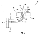
- FIGS 4 and 5 illustrate another forming apparatus 10b of the present invention in which the workpiece 100 is formed by two opposed friction stir forming tools 40 a, 40b .
- Each of the tools 40a , 40b can be similar to the tool 40 described above, including a shoulder 42a , 42b and a pin 44a , 44b extending therefrom.
- the tools 40a , 40b are positioned opposite the workpiece 100 so that the shoulders 42a , 42b are directed inward toward opposite sides 102 , 104 of the workpiece 100 .
- the workpiece 100 is supported by clamping members 38 or other support devices, which are secured to a base or frame 39 .
- the clamps 38 can be mechanical or hydraulic clamps that secure the workpiece 100 in position.
- the actuators 50a, 50b can translate along the length of the workpiece 100 , while maintaining the shoulders 42a, 42b in a parallel configuration.
- the actuators 50a, 50b can also rotate about an axis perpendicular to the longitudinal axis of the pins 44a, 44b , e.g., between the positions shown in Figures 4 and 5 , thereby urging the workpiece 100 to a curved configuration.
- More complex shapes, including three-dimensionally curved surfaces, can also be formed in this manner, e.g., by adjusting one or both of the friction stir forming tools 40a, 40b in two or more linear directions and about two or more axes of rotation.
- the workpiece 100 defines friction stir formed regions 114 that are defined by a refined granular structure.
- the pins 44a, 44b of the friction stir forming tools 40a, 40b can have a length that is about half of the thickness of the workpiece 100 or less so that the pins 44a, 44b do not contact one another when urged into the workpiece 100 from opposite sides.
- Each pin 44a, 44b can also be adjustable relative to the respective shoulder 42a, 42b , so that the pin 44a, 44b can be extended or retracted therefrom, as described above. Further, the pins 44a, 44b can be inserted into the workpiece 100 at slightly different positions so that one of the pins 44a, 44b "leads" the other pin 44a, 44b along the predetermined path.
- the friction stir formed regions 114 can extend through the entire thickness of the workpiece 100 .
- the tools 40a, 40b can be used to plasticize successive portions of the workpiece 100 until the entire workpiece 100 or only select portions of the workpiece 100 have been processed. Also, while a single workpiece 100 is illustrated in Figures 4 and 5 , it is understood that the workpiece 100 can be formed of multiple members and that the friction stir forming tools 40a, 40b can join the members by friction stir welding.
- a forming apparatus 10c can include two opposed shoulders 42c, 42d that are defined by a single self-reacting friction stir forming tool 40c .
- the shoulders 42c, 42d are connected by a pin 44c which extends through the workpiece 100 so that the first shoulder 42c is directed toward the first side 102 of the workpiece 100 and the second shoulder 42d is directed toward the second side 104 of the workpiece 100 .
- An actuator 50c similar to the actuators 50, 50a, 50b described above, is connected to the friction stir forming tool 40c and configured to adjust the tool 40c through the workpiece 100 .
- the pin 44c can be introduced into the workpiece 100 from an end of the workpiece 100 , or the pin 44c can be disconnected from one or both of the shoulders 42c, 42d so that the pin 44c can be disposed through a hole in the workpiece 100 and assembled with the shoulders 42c, 42d as shown.
- the actuator 50c can then adjust the tool 40c though the workpiece 100 along a nonplanar path so that the rotating pin 44c plasticizes portions of the workpiece 100 , and the shoulders 42c, 42d urge the workpiece 100 to a desired, nonplanar configuration.
- the workpiece 100 and any additional members 110 thereof can also be otherwise processed in the apparatus 10, 10a, 10b, 10c.
- the workpiece 100 can be machined to predetermined tolerances by a machining head (not shown), which can replace the friction stir forming tool 40, 40a, 40b, 40c on the actuators 50, 50a, 50 b, 50c or can be provided separately.
- heat treatments can be performed by heating and cooling the workpiece 100 to one or more predetermined temperatures according to a predetermined schedule. The heat treatment(s) can be performed while the workpiece 100 is secured in the apparatus 10, 10a, 10b, 10c, or the workpiece 100 can be removed from the apparatus 10, 10a, 10b, 10c and heat treated in a different device.
Landscapes
- Engineering & Computer Science (AREA)
- Mechanical Engineering (AREA)
- Pressure Welding/Diffusion-Bonding (AREA)
- Shaping Metal By Deep-Drawing, Or The Like (AREA)
- Mixers Of The Rotary Stirring Type (AREA)
Claims (24)
- Verfahren zur Formung eines Werkstücks zu einer gewünschten nicht planen Beschaffenheit mit einem Rührreibformungsgerät (40), das eine Schulter (42) und einen Pin (44) beschreibt, wobei das Verfahren umfasst:Bereitstellen eines Umformwerkzeugs (20) mit einer nicht planen Konturoberfläche (22), die der gewünschten Beschaffenheit des Werkstücks entspricht;Lagern des Werkstücks (100) zumindest teilweise gegen das Umformwerkzeug (20);Drängen der Schulter (22) des Formungsgeräts gegen das Werkstück (100) und zumindest teilweises Durchdringen des Werkstücks mit dem Pin, so dass das Werkstück gegen die Konturoberfläche gebogen wird;Drehen des Pins des Geräts innerhalb des Werkstücks zumindest teilweise während des Schritts des Drängens, um einen Abschnitt des Werkstücks zu plastifizieren; undEinstellen des Geräts in einem vorgegebenen Weg, welcher der Konturoberfläche des Umformwerkzeugs entspricht, zumindest teilweise während des Schritts des Drängens, so dass die Schulter das Werkstück zur gewünschten Beschaffenheit drängt und das Gerät einen Rührreib-geformten Bereich (114) mit einer verfeinerten Kornstruktur im Werkstück (100) schafft.
- Verfahren nach Anspruch 1, wobei der Bereitstellungsschritt das Bereitstellen eines Umformwerkzeugs umfasst, das eine kuppelförmige Konturoberfläche beschreibt, und der Einstellungsschritt das Bewegen des Geräts entlang der kuppelförmigen Konturoberfläche umfasst.
- Verfahren nach Anspruch 1 oder 2, wobei der Schritt des Drängens umfasst, dass der Pin in das Werkstück durch ungefähr die Hälfte der Dicke des Werkstücks gedrängt wird.
- Verfahren nach Anspruch 1, 2 oder 3, wobei der Einstellungsschritt das sukzessive Plastifizieren im Wesentlichen einer gesamten Oberfläche des Werkstücks und dadurch das Verfeinern der Kornstruktur des Werkstücks über die Oberfläche hinweg umfasst.
- Verfahren nach einem der Ansprüche 1 - 4, wobei der Einstellungsschritt das Halten der Schulter im Allgemeinen parallel zur Konturoberfläche umfasst.
- Verfahren nach einem der Ansprüche 1 - 5, wobei der Bereitstellungsschritt das Formen zumindest eines Detailmerkmals auf der Konturoberfläche des Umformwerkzeugs umfasst, so dass ein entsprechendes Detailmerkmal auf dem Werkstück geformt wird.
- Verfahren nach einem der Ansprüche 1 - 6, wobei der Lagerungsschritt das Bereitstellen zumindest zweier Strukturkomponenten als das Werkstück umfasst, wobei die Strukturkomponenten während des Einstellungsschritts zusammengefügt werden.
- Verfahren nach einem der Ansprüche 1 - 7, weiterhin umfassend das Drehen des Werkstücks in Zusammenhang mit dem Einstellungsschritt.
- Verfahren nach einem der Ansprüche 1 - 8, weiterhin umfassend das Einstellen des Pins in Bezug auf die Schulter.
- Verfahren zur Formung eines Werkstücks (100) mit erster und zweiter Seite (102, 104), die einander gegenüberliegen, zu einer gewünschten, nicht planen Beschaffenheit, wobei das Verfahren umfasst:Bereitstellen zumindest eines Rührreibformungsgeräts (40a, 40b), wobei das zumindest eine Gerät eine erste und zweite Schulter (42a, 42b) beschreibt, wobei die Schultern in entgegengesetzter Anordnung ausgebildet sind und im Allgemeinen einwärts gerichtet sind, wobei sich zumindest ein Pin (44a, 44b) wenigstens teilweise dazwischen erstreckt;Lagern des Werkstücks (100) zwischen der ersten und zweiten Schulter, so dass die erste Schulter (42a) zur ersten Seite (102) des Werkstücks gerichtet ist und die zweite Schulter (42b) zur zweiten Seite (104) des Werkstücks (100) gerichtet ist;Drängen der ersten Schulter (42a) gegen die erste Seite (102) des Werkstücks und der zweiten Schulter (42b) gegen die zweite Seite (104) des Werkstücks;Drehen des zumindest einen Pins (44a, 44b) innerhalb des Werkstücks wenigstens teilweise während des Schritts des Drängens, um einen Abschnitt des Werkstücks (100) zu plastifizieren; undEinstellen des zumindest einen Geräts entlang einem vorgegebenen Weg wenigstens teilweise während des Schritts des Drängens, so dass die Schultern das Werkstück zur gewünschten, nicht planen Beschaffenheit drängen und der zumindest eine Pin einen Rührreib-geformten Bereich (114) mit einer verfeinerten Kornstruktur im Werkstück (100) schafft.
- Verfahren nach einem der Ansprüche 1 - 10, wobei der Bereitstellungsschritt das Bereitstellen eines ersten und zweiten Rührreibformungsgeräts umfasst, wobei das erste Gerät die erste Schulter beschreibt und das zweite Gerät die zweite Schulter beschreibt, wobei jedes Gerät einen des zumindest einen Pins beschreibt, der sich von ihm aus erstreckt.
- Verfahren nach einem der Ansprüche 1 - 11, wobei der Bereitstellungsschritt das Bereitstellen der ersten und zweiten Schulter umfasst, die durch den sich dazwischen erstreckenden Pin verbunden sind.
- Verfahren nach einem der Ansprüche 1 - 12, weiterhin umfassend das Bereitstellen des Werkstücks, das von zumindest einem der Materialien aus jener Gruppe gebildet wird, die sich aus Stahl, Aluminium, Titan und Legierungen davon zusammensetzt.
- Verfahren nach einem der Ansprüche 1 - 13, wobei der Einstellungsschritt das Einstellen der Geräte durch einen gekrümmten Weg umfasst, so dass die Schultern das Werkstück zu einer gekrümmten Beschaffenheit drängen.
- Verfahren nach einem der Ansprüche 1 - 14, wobei der Einstellungsschritt umfasst, dass im Wesentlichen die gesamte erste und zweite Seite des Werkstücks sukzessive plastifiziert werden und dadurch die Kornstruktur des Werkstücks über die erste und zweite Seite hinweg verfeinert wird.
- Verfahren nach einem der Ansprüche 1 - 15, wobei der Einstellungsschritt das Halten der Schultern in einer im Allgemeinen parallelen Anordnung umfasst.
- Verfahren nach einem der Ansprüche 1 - 16, wobei der Einstellungsschritt das axiale Einstellen des zumindest einen Pins in Bezug auf die Schulter umfasst, von der aus der Pin sich erstreckt.
- Verfahren nach einem der Ansprüche 1 bis 17, wobei der Lagerungsschritt das Bereitstellen zumindest zweier Strukturkomponenten als das Werkstück umfasst, wobei die Strukturkomponenten während des Einstellungsschritts zusammengefügt werden.
- Vorrichtung (10) zur Formung eines Werkstücks (100) zu einer gewünschten, nicht planen Beschaffenheit, wobei die Vorrichtung umfasst:ein Umformwerkzeug (20) mit einer Konturoberfläche (22), die der gewünschten, nicht planen Beschaffenheit des Werkstücks entspricht;ein Rührreibformungsgerät (40), das eine Schulter (42) und einen rotierbaren Pin (44) beschreibt, der sich von der Schulter aus erstreckt, wobei das Gerät ausgebildet ist, um die Schulter und den Pin zur Konturoberfläche des Umformwerkzeugs zu drängen, so dass die Schulter das Werkstück gegen das Umformwerkzeug und zur gewünschten Beschaffenheit drängt, und der Pin wenigstens teilweise das Werkstück durchdringt und sich dreht, um einen Rührreib-geformten Bereich zu schaffen, der durch eine verfeinerte Kornstruktur definiert ist; undeinen Aktor (50) zum Einstellen des Rührreibformungsgeräts (40), wobei der Aktor ausgebildet ist, um das Gerät entlang einem vorgegebenen Weg, welcher der Konturoberfläche des Umformwerkzeugs entspricht, so einzustellen, dass die Schulter das Werkstück zur gewünschten, nicht planen Beschaffenheit drängt.
- Vorrichtung (10b, 10c) zur Formung eines Werkstücks zu einer gewünschten, nicht planen Beschaffenheit, wobei die Vorrichtung umfasst:zumindest ein Rührreibformungsgerät, mit einer ersten und einer zweiten Schulter (42a, 42b, 42c, 42d), die einander gegenüberliegen, und mit zumindest einem Pin (44a, 44b, 44c), der sich wenigstens teilweise zwischen den Schultern erstreckt, wobei die Schultern im Allgemeinen einwärts gerichtet sind, um ein Werkstück zwischen sich aufzunehmen; undzumindest einen Aktor (50a, 50b, 50c) zum Einstellen des Rührreibformungsgeräts, wobei der Aktor ausgebildet ist, um die Schultern in einer Richtung nach innen so einzustellen, dass die Schultern gegen gegenüberliegende Seiten des Werkstücks gedrängt werden, und um zu drehen und um das Werkstück wenigstens teilweise mit dem Pin zu durchdringen, um einen Rührreib-geformten Bereich zu schaffen, der durch eine verfeinerte Kornstruktur definiert ist, wobei der Aktor ausgebildet ist, um das Rührreibformungsgerät entlang einem vorgegebenen Weg, welcher der gewünschten, nicht planen Beschaffenheit des Werkstücks entspricht, so einzustellen, dass die Schultern das Werkstück zur gewünschten, nicht planen Beschaffenheit drängen.
- Gerät nach Anspruch 20, wobei sich der Pin von der ersten Schulter zur zweiten Schulter erstreckt.
- Gerät nach Anspruch 20 oder 21, wobei das Formungsgerät einen ersten und einen zweiten Pin aufweist, wobei der erste Pin sich von der ersten Schulter aus erstreckt und der zweite Pin sich von der zweiten Schulter aus erstreckt.
- Gerät, beinhaltend die Merkmale aus Anspruch 19 und 20, und/oder 21 und 22.
- Gerät nach einem der Ansprüche 20 - 23, zum Implementieren des Verfahrens nach einem der Ansprüche 1 - 20.
Applications Claiming Priority (2)
| Application Number | Priority Date | Filing Date | Title |
|---|---|---|---|
| US639033 | 1975-12-09 | ||
| US10/639,033 US7448528B2 (en) | 2003-08-12 | 2003-08-12 | Stir forming apparatus and method |
Publications (3)
| Publication Number | Publication Date |
|---|---|
| EP1506832A2 EP1506832A2 (de) | 2005-02-16 |
| EP1506832A3 EP1506832A3 (de) | 2009-04-22 |
| EP1506832B1 true EP1506832B1 (de) | 2010-02-24 |
Family
ID=33565224
Family Applications (1)
| Application Number | Title | Priority Date | Filing Date |
|---|---|---|---|
| EP04077223A Expired - Lifetime EP1506832B1 (de) | 2003-08-12 | 2004-08-03 | Verfahren und Vorrichtung zur drehenden Rührformung |
Country Status (7)
| Country | Link |
|---|---|
| US (2) | US7448528B2 (de) |
| EP (1) | EP1506832B1 (de) |
| JP (2) | JP5118801B2 (de) |
| KR (1) | KR101148379B1 (de) |
| CN (1) | CN100564006C (de) |
| AT (1) | ATE458578T1 (de) |
| DE (1) | DE602004025655D1 (de) |
Cited By (1)
| Publication number | Priority date | Publication date | Assignee | Title |
|---|---|---|---|---|
| DE102009052408A1 (de) * | 2009-11-10 | 2011-05-12 | Universität Paderborn | Verfahren zur Bearbeitung eines Werkstücks |
Families Citing this family (41)
| Publication number | Priority date | Publication date | Assignee | Title |
|---|---|---|---|---|
| US6726085B2 (en) * | 2002-05-14 | 2004-04-27 | The Boeing Company | Method and apparatus for producing a refined grain structure |
| KR100543160B1 (ko) * | 2003-10-01 | 2006-01-20 | 한국기계연구원 | 박판접합용 표면이동 마찰용접방법 |
| DE102005029882A1 (de) * | 2005-06-27 | 2006-12-28 | Gkss-Forschungszentrum Geesthacht Gmbh | Vorrichtung zum Reibrührschweißen |
| WO2007055864A2 (en) * | 2005-10-12 | 2007-05-18 | Surface Technology Holdings, Ltd | Improved integrally bladed rotating turbo machinery and method and apparatus for achieving the same |
| US7992761B2 (en) * | 2006-10-05 | 2011-08-09 | The Boeing Company | Process control system for friction stir welding |
| US8858853B2 (en) | 2008-04-04 | 2014-10-14 | The Boeing Company | Formed sheet metal composite tooling |
| US8408039B2 (en) * | 2008-10-07 | 2013-04-02 | Northwestern University | Microforming method and apparatus |
| US8322176B2 (en) * | 2009-02-11 | 2012-12-04 | Ford Global Technologies, Llc | System and method for incrementally forming a workpiece |
| EP2398620A4 (de) * | 2009-02-19 | 2017-03-29 | Blue Origin, LLC | Modularer reibschweisskopf sowie zugehörige systeme und verfahren |
| JP2010214468A (ja) * | 2009-02-23 | 2010-09-30 | Kumamoto Univ | 板材の成形方法及び装置 |
| US8776372B2 (en) * | 2009-09-11 | 2014-07-15 | GM Global Technology Operations LLC | Cast magnesium alloy wheels |
| US9079674B1 (en) | 2009-09-18 | 2015-07-14 | Blue Origin, Llc | Composite structures for aerospace vehicles, and associated systems and methods |
| DE102009044279B4 (de) * | 2009-10-16 | 2013-11-21 | Mag Europe Gmbh | Verfahren zur Herstellung eines Wandanschlussstücks und zugehöriges Wandanschlussstück |
| GB2473298B (en) * | 2009-11-13 | 2011-07-13 | Imp Innovations Ltd | A method of forming a component of complex shape from aluminium alloy sheet |
| US8783078B2 (en) | 2010-07-27 | 2014-07-22 | Ford Global Technologies, Llc | Method to improve geometrical accuracy of an incrementally formed workpiece |
| US8302442B2 (en) * | 2010-07-29 | 2012-11-06 | Ford Global Technologies, Llc | Method of incrementally forming a workpiece |
| WO2012081100A1 (ja) * | 2010-12-16 | 2012-06-21 | 三菱重工業株式会社 | 摩擦攪拌スポット接合装置、及びその部材支持器 |
| US8534530B2 (en) | 2011-04-27 | 2013-09-17 | Blue Origin, Llc | Inflatable ring for supporting friction welding workpieces, and associated systems and methods |
| DE102011114922A1 (de) * | 2011-10-06 | 2013-04-11 | Airbus Operations Gmbh | Fügevorrichtung zum Verbinden von Strukturbauteilen eines Luftfahrzeuges |
| DE102011114924A1 (de) | 2011-10-06 | 2013-04-11 | Airbus Operations Gmbh | Bewegbare Fügeeinrichtung zum Verbinden von Strukturbauteilen eines Luftfahrzeuges |
| US20140261900A1 (en) * | 2013-03-12 | 2014-09-18 | Lockheed Martin Corporation | Friction surface stir process |
| CN103820662A (zh) * | 2014-02-28 | 2014-05-28 | 宝山钢铁股份有限公司 | 一种增强锆元素对不含铝的镁合金铸造组织细化功效的方法 |
| JP6284444B2 (ja) * | 2014-06-25 | 2018-02-28 | 三菱重工業株式会社 | 摩擦撹拌接合方法及び摩擦撹拌接合装置 |
| JP6393931B2 (ja) * | 2014-10-15 | 2018-09-26 | 三菱重工エンジニアリング株式会社 | マグネシウム合金の塑性加工方法 |
| CN104607523B (zh) * | 2015-02-13 | 2017-03-15 | 上海交通大学 | 一种板料搅拌渐进复合成形装置及方法 |
| CN105013939B (zh) * | 2015-06-17 | 2017-05-17 | 武汉理工大学 | 基于自发热的搅拌摩擦成形装置及工艺 |
| DE102015010638A1 (de) * | 2015-08-13 | 2017-02-16 | Grenzebach Maschinenbau Gmbh | Vorrichtung und Verfahren zum homogenen Verschweißen flächig gebogener Strukturen durch Rührreibschweißen |
| KR102098217B1 (ko) * | 2016-03-31 | 2020-04-07 | 제이에프이 스틸 가부시키가이샤 | 구조용 강의 마찰 교반 접합 방법 및 장치 |
| US10279423B2 (en) | 2016-08-17 | 2019-05-07 | The Boeing Company | Apparatuses and methods for fabricating metal matrix composite structures |
| CN106624647B (zh) * | 2016-12-26 | 2019-02-19 | 南京航空航天大学 | 钛合金板材搭接装置及方法 |
| GB2563068B (en) * | 2017-06-02 | 2022-10-12 | Gkn Aerospace Services Ltd | Friction forming |
| CN107214231A (zh) * | 2017-06-16 | 2017-09-29 | 广东工业大学 | 一种提高铝合金板材深冲性能的加工方法 |
| DE102018111496B4 (de) * | 2018-05-14 | 2024-02-01 | Universität Stuttgart | Verfahren zum Rührreibschweißen |
| US11759837B1 (en) * | 2018-10-24 | 2023-09-19 | Abl Space Systems | Systems and methods for launch vehicle dome manufacturing |
| US12330214B1 (en) | 2019-02-11 | 2025-06-17 | Blue Origin Manufacturing, LLC | Printed porous media, such as for use in aerospace parts, and associated systems and methods |
| GB201918891D0 (en) * | 2019-12-19 | 2020-02-05 | Element Six Uk Ltd | Friction stir welding using a PCBN-based tool |
| WO2022010718A1 (en) * | 2020-07-09 | 2022-01-13 | Lam Research Corporation | Friction stir processing for corrosion resistance |
| WO2022239795A1 (ja) * | 2021-05-14 | 2022-11-17 | 川崎重工業株式会社 | 接合方法および接合体 |
| CN114570851A (zh) * | 2022-05-05 | 2022-06-03 | 太原科技大学 | 一种无缝金属气瓶内胆的成形工艺 |
| CN114951959B (zh) * | 2022-07-04 | 2023-03-24 | 河北科技大学 | 一种搅拌摩擦焊接工具 |
| DE102024001719A1 (de) * | 2024-05-28 | 2025-12-04 | Hydac Technology Gmbh | Verfahren |
Family Cites Families (53)
| Publication number | Priority date | Publication date | Assignee | Title |
|---|---|---|---|---|
| US3470720A (en) * | 1967-09-01 | 1969-10-07 | Phillip R Eklund | Method of making hollow balls for use in ball bearing and/or similar rolling operations |
| GB1501622A (en) * | 1972-02-16 | 1978-02-22 | Int Harvester Co | Metal shaping processes |
| GB1344066A (en) * | 1970-08-04 | 1974-01-16 | Secr Defence | Metal working |
| DE2148519A1 (de) * | 1971-09-29 | 1973-04-05 | Ottensener Eisenwerk Gmbh | Verfahren und vorrichtung zum erwaermen und boerdeln von ronden |
| DE3572081D1 (en) * | 1984-09-28 | 1989-09-07 | Philips Nv | Method of drape drawing a shadow mask for a colour display tube and device for such a method |
| US4998663A (en) * | 1989-12-22 | 1991-03-12 | Edison Polymer Innovation Corporation | Friction welding apparatus |
| DE4014405A1 (de) * | 1990-05-04 | 1991-11-07 | Eckehart Schulze | Verfahren zur steuerung der umlauf-bahnbewegungen der drueckrolle einer drueckmaschine und drueckmaschine zur durchfuehrung des verfahrens |
| US5262123A (en) * | 1990-06-06 | 1993-11-16 | The Welding Institute | Forming metallic composite materials by urging base materials together under shear |
| GB9119022D0 (en) * | 1991-09-05 | 1991-10-23 | Welding Inst | Friction forming |
| GB9125978D0 (en) * | 1991-12-06 | 1992-02-05 | Welding Inst | Hot shear butt welding |
| GB9309819D0 (en) * | 1993-05-13 | 1993-06-23 | Allwood Searle & Timney | Imprivements relating to friction welding |
| GB9414381D0 (en) * | 1994-07-15 | 1994-09-07 | British Nuclear Fuels Plc | A method of friction welding |
| US5611479A (en) * | 1996-02-20 | 1997-03-18 | Rockwell International Corporation | Friction stir welding total penetration technique |
| US5697544A (en) * | 1996-03-21 | 1997-12-16 | Boeing North American, Inc. | Adjustable pin for friction stir welding tool |
| US5713507A (en) * | 1996-03-21 | 1998-02-03 | Rockwell International Corporation | Programmable friction stir welding process |
| US5718366A (en) * | 1996-05-31 | 1998-02-17 | The Boeing Company | Friction stir welding tool for welding variable thickness workpieces |
| SE512230C2 (sv) * | 1996-06-20 | 2000-02-14 | Esab Ab | Anläggning för friktionsomrörningssvetsning |
| JP3311590B2 (ja) * | 1996-08-06 | 2002-08-05 | 株式会社日立製作所 | 摩擦溶接方法 |
| US6486262B1 (en) * | 1997-06-06 | 2002-11-26 | Nippon Zeon Co., Ltd. | Molding material for plastic lens |
| JP3598204B2 (ja) * | 1997-06-26 | 2004-12-08 | 昭和電工株式会社 | 摩擦撹拌接合法及び摩擦撹拌接合装置 |
| JP3070735B2 (ja) * | 1997-07-23 | 2000-07-31 | 株式会社日立製作所 | 摩擦攪拌接合方法 |
| JP3589863B2 (ja) * | 1997-07-23 | 2004-11-17 | 株式会社日立製作所 | 構造体および摩擦攪拌接合方法 |
| US5893507A (en) * | 1997-08-07 | 1999-04-13 | The United States Of America As Represented By The Administrator Of The National Aeronautics And Space Administration | Auto-adjustable pin tool for friction stir welding |
| SE9704800D0 (sv) * | 1997-12-19 | 1997-12-19 | Esab Ab | Anordning för svetsning |
| DE69940582D1 (de) * | 1998-01-29 | 2009-04-30 | Amino Corp | Vorrichtung zum herstellen von plattenmaterial |
| US6003228A (en) * | 1998-05-14 | 1999-12-21 | Wave Corporation | Method for making a decorative or jewelry item |
| US6070784A (en) * | 1998-07-08 | 2000-06-06 | The Boeing Company | Contact backup roller approach to FSW process |
| JP3449403B2 (ja) * | 1998-07-15 | 2003-09-22 | 日本軽金属株式会社 | 貫通摩擦攪拌接合用プローブ |
| US6421578B1 (en) * | 1999-02-12 | 2002-07-16 | Lockheed Martin Corporation | Stir-friction hot working control system |
| DE50004986D1 (de) * | 1999-03-24 | 2004-02-12 | Framatome Anp Gmbh | Verfahren und vorrichtung zum verschweissen zweier werkstücke |
| JP2000336465A (ja) * | 1999-05-25 | 2000-12-05 | Toyota Motor Corp | アルミニウム鋳物の部分強化方法 |
| US6247634B1 (en) * | 1999-06-30 | 2001-06-19 | Mce Technologies Incorporated | Method and apparatus for forming a stir welded joint at meeting cylindrical edges |
| AU7475200A (en) * | 1999-09-03 | 2001-04-10 | Lockheed Martin Corporation | Friction stir welding as a rivet replacement technology |
| US6469617B1 (en) * | 1999-09-10 | 2002-10-22 | Ncr Corporation | Method of restoring information for display by an electronic price label |
| JP2001225179A (ja) * | 2000-02-15 | 2001-08-21 | Hitachi Ltd | 接合構造物 |
| US6299050B1 (en) * | 2000-02-24 | 2001-10-09 | Hitachi, Ltd. | Friction stir welding apparatus and method |
| US6237835B1 (en) * | 2000-02-29 | 2001-05-29 | The Boeing Company | Method and apparatus for backing up a friction stir weld joint |
| JP3575748B2 (ja) * | 2000-03-06 | 2004-10-13 | 株式会社日立製作所 | 摩擦攪拌接合方法 |
| JP2001252774A (ja) * | 2000-03-10 | 2001-09-18 | Showa Denko Kk | 摩擦攪拌接合方法 |
| US6532786B1 (en) * | 2000-04-19 | 2003-03-18 | D-J Engineering, Inc. | Numerically controlled forming method |
| JP3400409B2 (ja) * | 2000-04-28 | 2003-04-28 | マツダ株式会社 | 接合方法及び接合装置 |
| US6450395B1 (en) * | 2000-08-01 | 2002-09-17 | The Boeing Company | Method and apparatus for friction stir welding tubular members |
| JP3346380B2 (ja) * | 2000-09-21 | 2002-11-18 | 日本軽金属株式会社 | 鋳物表面の微細空隙除去方法およびこれに用いる攪拌ツール |
| JP3763734B2 (ja) * | 2000-10-27 | 2006-04-05 | 株式会社日立製作所 | パネル部材の加工方法 |
| JP4646421B2 (ja) * | 2001-03-05 | 2011-03-09 | 公 西原 | 摩擦攪拌成型方法 |
| US6660106B1 (en) * | 2001-08-22 | 2003-12-09 | The Boeing Company | Methods of manufacture of spin-forming blanks, particularly for fabrication of rocket domes |
| JP4190179B2 (ja) * | 2001-12-18 | 2008-12-03 | 住友軽金属工業株式会社 | 摩擦撹拌接合方法 |
| US6908690B2 (en) * | 2002-04-29 | 2005-06-21 | The Boeing Company | Method and apparatus for friction stir welding |
| US6854634B2 (en) * | 2002-05-14 | 2005-02-15 | The Boeing Company | Method of manufacturing rivets having high strength and formability |
| US6726085B2 (en) * | 2002-05-14 | 2004-04-27 | The Boeing Company | Method and apparatus for producing a refined grain structure |
| JP3726786B2 (ja) * | 2002-07-31 | 2005-12-14 | マツダ株式会社 | 接合方法及び接合ツール |
| US6866180B2 (en) * | 2003-02-18 | 2005-03-15 | Rockwell Scientific Licensing, Llc | Thick-section metal forming via friction stir processing |
| US7198189B2 (en) * | 2004-09-28 | 2007-04-03 | Alcoa Inc. | Multi-shouldered fixed bobbin tools for simultaneous friction stir welding of multiple parallel walls between parts |
-
2003
- 2003-08-12 US US10/639,033 patent/US7448528B2/en not_active Expired - Lifetime
-
2004
- 2004-08-03 DE DE602004025655T patent/DE602004025655D1/de not_active Expired - Lifetime
- 2004-08-03 AT AT04077223T patent/ATE458578T1/de not_active IP Right Cessation
- 2004-08-03 EP EP04077223A patent/EP1506832B1/de not_active Expired - Lifetime
- 2004-08-10 KR KR1020040062920A patent/KR101148379B1/ko not_active Expired - Lifetime
- 2004-08-11 JP JP2004234543A patent/JP5118801B2/ja not_active Expired - Lifetime
- 2004-08-12 CN CNB2004100874098A patent/CN100564006C/zh not_active Expired - Lifetime
-
2008
- 2008-08-18 US US12/193,253 patent/US7971463B2/en not_active Expired - Lifetime
-
2012
- 2012-09-11 JP JP2012199036A patent/JP5431553B2/ja not_active Expired - Lifetime
Cited By (1)
| Publication number | Priority date | Publication date | Assignee | Title |
|---|---|---|---|---|
| DE102009052408A1 (de) * | 2009-11-10 | 2011-05-12 | Universität Paderborn | Verfahren zur Bearbeitung eines Werkstücks |
Also Published As
| Publication number | Publication date |
|---|---|
| JP5431553B2 (ja) | 2014-03-05 |
| JP2013010142A (ja) | 2013-01-17 |
| EP1506832A3 (de) | 2009-04-22 |
| ATE458578T1 (de) | 2010-03-15 |
| CN100564006C (zh) | 2009-12-02 |
| JP5118801B2 (ja) | 2013-01-16 |
| US20080302154A1 (en) | 2008-12-11 |
| KR20050019041A (ko) | 2005-02-28 |
| CN1623763A (zh) | 2005-06-08 |
| US20050035179A1 (en) | 2005-02-17 |
| US7971463B2 (en) | 2011-07-05 |
| JP2005059101A (ja) | 2005-03-10 |
| DE602004025655D1 (de) | 2010-04-08 |
| KR101148379B1 (ko) | 2012-05-23 |
| US7448528B2 (en) | 2008-11-11 |
| EP1506832A2 (de) | 2005-02-16 |
Similar Documents
| Publication | Publication Date | Title |
|---|---|---|
| EP1506832B1 (de) | Verfahren und Vorrichtung zur drehenden Rührformung | |
| EP1285707B1 (de) | Verfahren zur Herstellung von kuppelförmigen Gegenständen mit grossem Durchmesser | |
| US9604318B2 (en) | Apparatus and method for producing a tailored sheet metal strip or metal profile | |
| US7398911B2 (en) | Structural assemblies and preforms therefor formed by friction welding | |
| EP1790425B1 (de) | Absetzendes drehendes Reibrührschweissverfahren unter Verwendung eines Zusatzwerkstoffes; Einrichtung mit einer Matrize zum Formen des Schweissnahtprofiles und zum Vermeiden von Graten | |
| US6779708B2 (en) | Joining structural members by friction welding | |
| JP4825019B2 (ja) | 金属材の曲げ加工方法、曲げ加工装置および曲げ加工設備列、並びにそれらを用いた曲げ加工製品 | |
| US6866180B2 (en) | Thick-section metal forming via friction stir processing | |
| Buffa et al. | Joining by forming technologies: current solutions and future trends | |
| EP0921892B1 (de) | Linear-reibschweissverfahren zum herstellen von radfelgen | |
| EP1029627B1 (de) | Reibschweissverfahren zum Verbinden von metallischen Werkstücken | |
| EP1512470B1 (de) | Anpassbarer Dorn zum Fliessdrücken, Vorrichtung zum Fliessdrücken mit einem solchen Dorn, sowie Verfahren zum Fliessdrücken | |
| US11524325B2 (en) | Friction forming | |
| Zhi-Hong et al. | Friction stir welding of aluminum alloys | |
| US12434326B2 (en) | Method for friction stir welding or processing high strength steel | |
| WO2024218661A1 (en) | Vehicle member assembly and method for manufacturing the same | |
| Billur et al. | Post-Forming Operations | |
| KR20250093047A (ko) | 용접부 잔류응력 저감 장치 및 방법 |
Legal Events
| Date | Code | Title | Description |
|---|---|---|---|
| PUAI | Public reference made under article 153(3) epc to a published international application that has entered the european phase |
Free format text: ORIGINAL CODE: 0009012 |
|
| AK | Designated contracting states |
Kind code of ref document: A2 Designated state(s): AT BE BG CH CY CZ DE DK EE ES FI FR GB GR HU IE IT LI LU MC NL PL PT RO SE SI SK TR |
|
| AX | Request for extension of the european patent |
Extension state: AL HR LT LV MK |
|
| PUAL | Search report despatched |
Free format text: ORIGINAL CODE: 0009013 |
|
| AK | Designated contracting states |
Kind code of ref document: A3 Designated state(s): AT BE BG CH CY CZ DE DK EE ES FI FR GB GR HU IE IT LI LU MC NL PL PT RO SE SI SK TR |
|
| AX | Request for extension of the european patent |
Extension state: AL HR LT LV MK |
|
| GRAP | Despatch of communication of intention to grant a patent |
Free format text: ORIGINAL CODE: EPIDOSNIGR1 |
|
| 17P | Request for examination filed |
Effective date: 20091001 |
|
| GRAS | Grant fee paid |
Free format text: ORIGINAL CODE: EPIDOSNIGR3 |
|
| AKX | Designation fees paid |
Designated state(s): AT BE BG CH CY LI |
|
| GRAA | (expected) grant |
Free format text: ORIGINAL CODE: 0009210 |
|
| REG | Reference to a national code |
Ref country code: DE Ref legal event code: 8566 |
|
| AK | Designated contracting states |
Kind code of ref document: B1 Designated state(s): AT BE BG CH CY CZ DE DK EE ES FI FR GB GR HU IE IT LI LU MC NL PL PT RO SE SI SK TR |
|
| REG | Reference to a national code |
Ref country code: GB Ref legal event code: FG4D |
|
| REG | Reference to a national code |
Ref country code: CH Ref legal event code: EP |
|
| REG | Reference to a national code |
Ref country code: IE Ref legal event code: FG4D |
|
| REF | Corresponds to: |
Ref document number: 602004025655 Country of ref document: DE Date of ref document: 20100408 Kind code of ref document: P |
|
| REG | Reference to a national code |
Ref country code: DE Ref legal event code: R096 Ref document number: 602004025655 Country of ref document: DE Effective date: 20100408 |
|
| REG | Reference to a national code |
Ref country code: NL Ref legal event code: VDEP Effective date: 20100224 |
|
| PG25 | Lapsed in a contracting state [announced via postgrant information from national office to epo] |
Ref country code: PT Free format text: LAPSE BECAUSE OF FAILURE TO SUBMIT A TRANSLATION OF THE DESCRIPTION OR TO PAY THE FEE WITHIN THE PRESCRIBED TIME-LIMIT Effective date: 20100625 |
|
| PG25 | Lapsed in a contracting state [announced via postgrant information from national office to epo] |
Ref country code: SI Free format text: LAPSE BECAUSE OF FAILURE TO SUBMIT A TRANSLATION OF THE DESCRIPTION OR TO PAY THE FEE WITHIN THE PRESCRIBED TIME-LIMIT Effective date: 20100224 Ref country code: PL Free format text: LAPSE BECAUSE OF FAILURE TO SUBMIT A TRANSLATION OF THE DESCRIPTION OR TO PAY THE FEE WITHIN THE PRESCRIBED TIME-LIMIT Effective date: 20100224 Ref country code: FI Free format text: LAPSE BECAUSE OF FAILURE TO SUBMIT A TRANSLATION OF THE DESCRIPTION OR TO PAY THE FEE WITHIN THE PRESCRIBED TIME-LIMIT Effective date: 20100224 Ref country code: AT Free format text: LAPSE BECAUSE OF FAILURE TO SUBMIT A TRANSLATION OF THE DESCRIPTION OR TO PAY THE FEE WITHIN THE PRESCRIBED TIME-LIMIT Effective date: 20100224 |
|
| PG25 | Lapsed in a contracting state [announced via postgrant information from national office to epo] |
Ref country code: SE Free format text: LAPSE BECAUSE OF FAILURE TO SUBMIT A TRANSLATION OF THE DESCRIPTION OR TO PAY THE FEE WITHIN THE PRESCRIBED TIME-LIMIT Effective date: 20100224 Ref country code: RO Free format text: LAPSE BECAUSE OF FAILURE TO SUBMIT A TRANSLATION OF THE DESCRIPTION OR TO PAY THE FEE WITHIN THE PRESCRIBED TIME-LIMIT Effective date: 20100224 Ref country code: NL Free format text: LAPSE BECAUSE OF FAILURE TO SUBMIT A TRANSLATION OF THE DESCRIPTION OR TO PAY THE FEE WITHIN THE PRESCRIBED TIME-LIMIT Effective date: 20100224 Ref country code: GR Free format text: LAPSE BECAUSE OF FAILURE TO SUBMIT A TRANSLATION OF THE DESCRIPTION OR TO PAY THE FEE WITHIN THE PRESCRIBED TIME-LIMIT Effective date: 20100525 Ref country code: ES Free format text: LAPSE BECAUSE OF FAILURE TO SUBMIT A TRANSLATION OF THE DESCRIPTION OR TO PAY THE FEE WITHIN THE PRESCRIBED TIME-LIMIT Effective date: 20100604 Ref country code: EE Free format text: LAPSE BECAUSE OF FAILURE TO SUBMIT A TRANSLATION OF THE DESCRIPTION OR TO PAY THE FEE WITHIN THE PRESCRIBED TIME-LIMIT Effective date: 20100224 Ref country code: CY Free format text: LAPSE BECAUSE OF FAILURE TO SUBMIT A TRANSLATION OF THE DESCRIPTION OR TO PAY THE FEE WITHIN THE PRESCRIBED TIME-LIMIT Effective date: 20100224 Ref country code: BE Free format text: LAPSE BECAUSE OF FAILURE TO SUBMIT A TRANSLATION OF THE DESCRIPTION OR TO PAY THE FEE WITHIN THE PRESCRIBED TIME-LIMIT Effective date: 20100224 |
|
| PG25 | Lapsed in a contracting state [announced via postgrant information from national office to epo] |
Ref country code: SK Free format text: LAPSE BECAUSE OF FAILURE TO SUBMIT A TRANSLATION OF THE DESCRIPTION OR TO PAY THE FEE WITHIN THE PRESCRIBED TIME-LIMIT Effective date: 20100224 Ref country code: CZ Free format text: LAPSE BECAUSE OF FAILURE TO SUBMIT A TRANSLATION OF THE DESCRIPTION OR TO PAY THE FEE WITHIN THE PRESCRIBED TIME-LIMIT Effective date: 20100224 Ref country code: BG Free format text: LAPSE BECAUSE OF FAILURE TO SUBMIT A TRANSLATION OF THE DESCRIPTION OR TO PAY THE FEE WITHIN THE PRESCRIBED TIME-LIMIT Effective date: 20100524 |
|
| PLBE | No opposition filed within time limit |
Free format text: ORIGINAL CODE: 0009261 |
|
| STAA | Information on the status of an ep patent application or granted ep patent |
Free format text: STATUS: NO OPPOSITION FILED WITHIN TIME LIMIT |
|
| PG25 | Lapsed in a contracting state [announced via postgrant information from national office to epo] |
Ref country code: DK Free format text: LAPSE BECAUSE OF FAILURE TO SUBMIT A TRANSLATION OF THE DESCRIPTION OR TO PAY THE FEE WITHIN THE PRESCRIBED TIME-LIMIT Effective date: 20100224 |
|
| 26N | No opposition filed |
Effective date: 20101125 |
|
| REG | Reference to a national code |
Ref country code: DE Ref legal event code: R097 Ref document number: 602004025655 Country of ref document: DE Effective date: 20101125 |
|
| PG25 | Lapsed in a contracting state [announced via postgrant information from national office to epo] |
Ref country code: IT Free format text: LAPSE BECAUSE OF FAILURE TO SUBMIT A TRANSLATION OF THE DESCRIPTION OR TO PAY THE FEE WITHIN THE PRESCRIBED TIME-LIMIT Effective date: 20100224 Ref country code: MC Free format text: LAPSE BECAUSE OF NON-PAYMENT OF DUE FEES Effective date: 20100831 |
|
| REG | Reference to a national code |
Ref country code: CH Ref legal event code: PL |
|
| PG25 | Lapsed in a contracting state [announced via postgrant information from national office to epo] |
Ref country code: LI Free format text: LAPSE BECAUSE OF NON-PAYMENT OF DUE FEES Effective date: 20100831 Ref country code: CH Free format text: LAPSE BECAUSE OF NON-PAYMENT OF DUE FEES Effective date: 20100831 |
|
| PG25 | Lapsed in a contracting state [announced via postgrant information from national office to epo] |
Ref country code: IE Free format text: LAPSE BECAUSE OF NON-PAYMENT OF DUE FEES Effective date: 20100803 |
|
| PG25 | Lapsed in a contracting state [announced via postgrant information from national office to epo] |
Ref country code: LU Free format text: LAPSE BECAUSE OF NON-PAYMENT OF DUE FEES Effective date: 20100803 Ref country code: HU Free format text: LAPSE BECAUSE OF FAILURE TO SUBMIT A TRANSLATION OF THE DESCRIPTION OR TO PAY THE FEE WITHIN THE PRESCRIBED TIME-LIMIT Effective date: 20100825 |
|
| PG25 | Lapsed in a contracting state [announced via postgrant information from national office to epo] |
Ref country code: TR Free format text: LAPSE BECAUSE OF FAILURE TO SUBMIT A TRANSLATION OF THE DESCRIPTION OR TO PAY THE FEE WITHIN THE PRESCRIBED TIME-LIMIT Effective date: 20100224 |
|
| REG | Reference to a national code |
Ref country code: FR Ref legal event code: PLFP Year of fee payment: 13 |
|
| REG | Reference to a national code |
Ref country code: FR Ref legal event code: PLFP Year of fee payment: 14 |
|
| REG | Reference to a national code |
Ref country code: FR Ref legal event code: PLFP Year of fee payment: 15 |
|
| P01 | Opt-out of the competence of the unified patent court (upc) registered |
Effective date: 20230516 |
|
| PGFP | Annual fee paid to national office [announced via postgrant information from national office to epo] |
Ref country code: GB Payment date: 20230828 Year of fee payment: 20 |
|
| PGFP | Annual fee paid to national office [announced via postgrant information from national office to epo] |
Ref country code: FR Payment date: 20230825 Year of fee payment: 20 Ref country code: DE Payment date: 20230829 Year of fee payment: 20 |
|
| REG | Reference to a national code |
Ref country code: DE Ref legal event code: R071 Ref document number: 602004025655 Country of ref document: DE |
|
| REG | Reference to a national code |
Ref country code: GB Ref legal event code: PE20 Expiry date: 20240802 |
|
| PG25 | Lapsed in a contracting state [announced via postgrant information from national office to epo] |
Ref country code: GB Free format text: LAPSE BECAUSE OF EXPIRATION OF PROTECTION Effective date: 20240802 |
|
| PG25 | Lapsed in a contracting state [announced via postgrant information from national office to epo] |
Ref country code: GB Free format text: LAPSE BECAUSE OF EXPIRATION OF PROTECTION Effective date: 20240802 |