EP1506934A2 - Hängekranbahn und Hängekranbahnprofil - Google Patents
Hängekranbahn und Hängekranbahnprofil Download PDFInfo
- Publication number
- EP1506934A2 EP1506934A2 EP04018934A EP04018934A EP1506934A2 EP 1506934 A2 EP1506934 A2 EP 1506934A2 EP 04018934 A EP04018934 A EP 04018934A EP 04018934 A EP04018934 A EP 04018934A EP 1506934 A2 EP1506934 A2 EP 1506934A2
- Authority
- EP
- European Patent Office
- Prior art keywords
- carriage
- profile
- crane
- drive
- suspended
- Prior art date
- Legal status (The legal status is an assumption and is not a legal conclusion. Google has not performed a legal analysis and makes no representation as to the accuracy of the status listed.)
- Granted
Links
Images




Classifications
-
- B—PERFORMING OPERATIONS; TRANSPORTING
- B66—HOISTING; LIFTING; HAULING
- B66C—CRANES; LOAD-ENGAGING ELEMENTS OR DEVICES FOR CRANES, CAPSTANS, WINCHES, OR TACKLES
- B66C11/00—Trolleys or crabs, e.g. operating above runways
- B66C11/02—Trolleys or crabs, e.g. operating above runways with operating gear or operator's cabin suspended, or laterally offset, from runway or track
- B66C11/04—Underhung trolleys
- B66C11/06—Underhung trolleys running on monorails
-
- B—PERFORMING OPERATIONS; TRANSPORTING
- B66—HOISTING; LIFTING; HAULING
- B66C—CRANES; LOAD-ENGAGING ELEMENTS OR DEVICES FOR CRANES, CAPSTANS, WINCHES, OR TACKLES
- B66C13/00—Other constructional features or details
- B66C13/12—Arrangements of means for transmitting pneumatic, hydraulic, or electric power to movable parts of devices
-
- B—PERFORMING OPERATIONS; TRANSPORTING
- B66—HOISTING; LIFTING; HAULING
- B66C—CRANES; LOAD-ENGAGING ELEMENTS OR DEVICES FOR CRANES, CAPSTANS, WINCHES, OR TACKLES
- B66C7/00—Runways, tracks or trackways for trolleys or cranes
- B66C7/02—Runways, tracks or trackways for trolleys or cranes for underhung trolleys or cranes
-
- B—PERFORMING OPERATIONS; TRANSPORTING
- B66—HOISTING; LIFTING; HAULING
- B66C—CRANES; LOAD-ENGAGING ELEMENTS OR DEVICES FOR CRANES, CAPSTANS, WINCHES, OR TACKLES
- B66C7/00—Runways, tracks or trackways for trolleys or cranes
- B66C7/08—Constructional features of runway rails or rail mountings
Definitions
- the invention relates to a suspension crane track and a profile for a suspension crane track.
- Craneway systems are often used in the automotive industry Conveyor systems for moving loads from one point to another or as conveyor systems for assembly machines, such as Pneumatic screwdrivers, welders, handling robots or the like Application. It comes more and more accurate to the position Transport as well as the path detection of the crane runway Facility importance too. Finally, crane runway systems relatively easy to assemble and in terms of be convertible to a changing requirement profile.
- Crane rail systems are known in which the carriages via drive pinion with an outside on the crane track rail cooperate provided toothing. This is the problem the slip eliminated with driven friction wheels. It is However, relatively expensive, such gears outside to provide the crane track rail, especially the crane track rails usually consist of extruded aluminum sections on the Racks or racks made of a harder metal applied Need to become.
- the invention is therefore based on the object, a completely to create a new suspension crane runway where the carriages are precise guided and positionally accurate are movable
- a suspension crane track comprising at least one crane track rail and at least one carriage guided on the crane rail track, wherein the crane track rail consists of several sections of a Hollow profile is composed of the carriage on an inside the raceway formed of the hollow profile is guided, the carriage Has at least one electric drive over a provided within the hollow profile with energy supply Energy is fed and where the carriage over completely inside the hollow profile arranged drive means within the same is arranged movable.
- a suspension crane track is provided with a crane track rail provided in which the power supply as well as parts of the drive means are integrated for the carriages.
- the carriages can with their rollers tilt-proof within the profile be guided.
- the whole arrangement is constructive especially compact and the drive means for the carriage are protected arranged within the crane rail track designed as a hollow profile, so that thereby a trouble-free operation like is guaranteed.
- At least one toothed drive is used as drive means provided, wherein the pinion comprises a rack, in the at least one drive pinion engages the carriage.
- the pinion can be used for exact positioning of the carriage.
- Such an exact position determination of the carriage is For example, then desirable if about this mounting tool be guided during tape assembly.
- the worker pulls the carriage with it battered compressed air or electric screwdriver behind ago.
- the integrated distance measurement can be used in each case determine the current position of the carriage exactly.
- the invention is as a driving stick in the interior of the hollow profile strained, fixed arranged toothed belt provided.
- a timing belt can be made of plastic, for example be. This can be relatively easy inside the Define hollow profiles.
- the toothed belt is in a profile groove of the hollow profile retracted and is form-fitting transversely to the pulling direction of this held.
- the separation points are each as an oblique cut designed so that no bumping of the wheels when driving over the rail joint occurs.
- the separation point in the plan view are approximately V-shaped.
- power supply is preferably at least one busbar provided, wherein the drive of the carriage at least comprising a current collector cooperating with the busbar.
- This pantograph can, for example, as a sliding contact be educated.
- the hollow profile may be at least a first in the installed position upper and a second mounting position in the lower profile chamber include, wherein the first profile chamber expediently the energy supply and the drive means receives and the second profile chamber the Trajectory for the carriage trains.
- the cross section of the crane track rail is approximately C-shaped configured, wherein the mounting position in the lower profile opening of the c-shaped profile a passage slot for the Lifting means of the carriage forms.
- this is designed as monorail suspension, it is but of course also possible, this as a multi-track monorail with several parallel rail tracks train.
- a crane runway profile is provided, which is designed as a hollow profile and within which at least a first in installation position upper and a second in Mounting position lower chamber are formed, wherein at least one Chamber as a raceway for the wheels of a carriage and at least a chamber for receiving the power supply and at least a part of the drive means for the carriage is.
- the profile cross-section may be configured approximately C-shaped, wherein in the installation position lower profile opening a passage slot for load attachment means of the carriage.
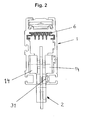
- the Suspension crane track includes the Suspension crane track according to the invention at least one crane track rail 1 and a run on the crane rail track 1 carriage 2.
- the crane track rail 1 is as aluminum hollow profile with formed approximately C-shaped cross section, wherein within the Hollow profiles in an installed position upper first chamber 3 and a are provided in the installed position lower second chamber 4.
- the chambers 3, 4 are by inwardly directed profile webs 5 from each other separated.
- the first chamber 3 serves to receive a Busbar 6 and a toothed belt 7 as a drive means for the carriage 2.
- the poles 8 of the bus bar 6 are formed and aligned, that between these the sliding contacts 9 of the on Carriage 2 arranged pantograph 10 can dive.
- the in a complementary thereto formed first groove channel 12th can be inserted.
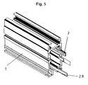
- a second groove channel 13 is provided, the Timing belt 7, as shown in Figure 5, receives.
- the second Groove channel 13, like the first groove channel 12 has an approximately C-shaped Cross-sectional profile on.
- the toothed belt 7 has a Carrier tape on, running slightly wider than the teeth is, so that the toothed belt 7 form-fitting manner in the second groove channel 13 can be retracted so that the teeth in the Profile interior points. The toothed belt 7 is then tensioned end established.
- the second chamber 4 forms a raceway or an impeller channel for the rollers 14 of the carriage 2 off.
- This impeller channel becomes upper side by the upper profile webs 5 and the lower side formed by lower profile webs or profile legs 15.
- the distance between the upper profile webs 5 and the lower Profile legs 15 is slightly larger than the diameter the rollers 14, so that the carriage 2 tip over within the profile.
- the cross-sectionally C-shaped profile of the crane track rail has a lower profile opening, which is considered to be in Lengthwise direction of the profile extending passage 16th is trained.
- the passage slot 16 serves for one of Passing through a part of the carriage 2, to the loads or handling devices can be posted, on the other hand this serves the centering of the carriage 2 means on the carriage 2 provided centering rollers 17.
- the centering rollers 17 roll on the formed by the passage slot 16 Inside surfaces off.
- the drive of the carriage 2 can be seen in FIG.
- the carriage 2 comprises an electric motor 18, via the Busbar 6 and the sliding contacts 9 of the pantograph 10th is powered by electricity.
- the electric motor 18 drives over one Output shaft 19, a bevel gear 20.
- the bevel gear 20 includes a spur gear 21 which meshes with a bevel gear 22.
- the bevel gear 22 is rotatable with a perpendicular to the Output shaft 19 extending shaft 23 connected and interspersed a pivotally mounted about the shaft 23 rocker 24, the about the shaft 23 by means of an actuating mechanism, not shown is pivotable.
- actuating mechanism not shown is pivotable.
- End of the rocker 24 is on this a drive pinion 25th rotatably mounted.
- the drive pinion 25 is in turn by a with the shaft 23 rotatably connected first auxiliary pinion 26 a driven by a second auxiliary pinion 26 b.
- first auxiliary pinion 26 a driven by a second auxiliary pinion 26 b.
- a third Grooved channel 27 is provided which receives a magnetic tape 28, about which integrated in the carriage 2 reading heads a incremental direct path measurement is possible.
- a rib 29 is provided on an inner surface of the passage slot 16 which receives a magnetic tape 28, about which integrated in the carriage 2 reading heads a incremental direct path measurement is possible.
- the Groove bottom of the third groove channel 27 is provided with a rib 29, which protrudes so far into the groove channel 27 that the magnetic tape pressed to the front profile edge to an accurate To pretend position to the read head 31 of the carriage 2.
- the freedom of the upper and lower Edge of the magnetic tape 28 ensures that this slightly over long lengths of the crane track rail 1 in the respective groove channel 27 is retractable.
- a fourth groove channel is called, the extends in the second chamber 4 and according to the third groove channel 27 is formed.
- this fourth groove channel 30 may be provided, for example, another steel strip, with magnetic elements or magnetic strips of any length can be fitted, which for the sensor of z. B. position detection, Switching functions, speed controls, etc. can be used.
Landscapes
- Engineering & Computer Science (AREA)
- Mechanical Engineering (AREA)
- Carriers, Traveling Bodies, And Overhead Traveling Cranes (AREA)
- Load-Engaging Elements For Cranes (AREA)
- Control And Safety Of Cranes (AREA)
Abstract
Description
- Figur 1
- einen Querschnitt durch eine Kranbahnschiene der erfindungsgemäßen Hängekranbahn,
- Figur 2
- eine schematische Ansicht der Kranbahnschiene mit in dieser eingesetztem Laufwagen, teilweise im Schnitt,
- Figur 3
- eine Ansicht des Laufwagens,
- Figur 4
- ein Teilstück der in die Kranbahnschiene eingesetzten Stromschiene,
- Figur 5
- eine perspektivische Ansicht eines Abschnitts der Kranbahnschiene,
- Figur 6
- eine Seitenansicht der Antriebsmittel des Laufwagens und
- Figur 7
- eine perspektivische Ansicht der Antriebsmittel des Laufwagens.
- 1
- Kranbahnschiene
- 2
- Laufwagen
- 3
- erste Kammer
- 4
- zweite Kammer
- 5
- obere Profilstege
- 6
- Stromschiene
- 7
- Zahnriemen
- 8
- Pole
- 9
- Schleifkontakte
- 10
- Stromabnehmer
- 11
- Schwalbenschwanzführung
- 12
- erster Nutkanal
- 13
- zweiter Nutkanal
- 14
- Laufrollen
- 15
- Profilschenkel
- 16
- Durchtrittsschlitz
- 17
- Zentrierrollen
- 18
- Elektromotor
- 19
- Antriebswelle
- 20
- Kegelradgetriebe
- 21
- Stirnrad
- 22
- Kegelrad
- 23
- Welle
- 24
- Wippe
- 25
- Antriebsritzel
- 26 a, b
- Hilfsritzel
- 27
- dritter Nutkanal
- 28
- Magnetband
- 29
- Rippe
- 30
- vierter Nutkanal
- 31
- Lesekopf
Claims (14)
- Hängekranbahn umfassend wenigstens eine Kranbahnschiene (1) und wenigstens einen an der Kranbahnschiene (1) geführten Laufwagen (2), wobei die Kranbahnschiene aus mehreren Abschnitten eines Hohlprofils zusammengesetzt ist, der Laufwagen (2) auf einer innerhalb des Hohlprofils gebildeten Laufbahn geführt ist, der Laufwagen wenigstens einen elektrischen Antrieb aufweist, der über eine innerhalb des Hohlprofils vorgesehene Energiezufuhr mit Energie gespeist wird und wobei der Laufwagen (2) über vollständig im Inneren des Hohlprofils angeordnete Antriebsmittel innerhalb desselben verfahrbar angeordnet ist.
- Hängekranbahn nach Anspruch 1, dadurch gekennzeichnet, dass als Antriebsmittel wenigstens ein Zahntrieb vorgesehen ist.
- Hängekranbahn nach Anspruch 2, dadurch gekennzeichnet, dass der Zahntrieb wenigstens einen Triebstock umfasst, in den wenigstens ein Antriebsritzel (25) am Laufwagen (2) eingreift.
- Hängekranbahn nach Anspruch 3, dadurch gekennzeichnet, dass als Triebstock ein im Inneren des Hohlprofils gespannter, feststehend angeordneter Zahnriemen (7) vorgesehen ist.
- Hängekranbahn nach Anspruch 4, dadurch gekennzeichnet, dass der Zahnriemen (7) in eine Profilnut des Hohlprofils eingezogen ist und von dieser quer zur Zugrichtung formschlüssig gehalten wird.
- Hängekranbahn nach einem der Ansprüche 4 oder 5, dadurch gekennzeichnet, dass der Zahnriemen (7) unter Zugspannung jeweils endseitig festgelegt ist.
- Hängekranbahn nach einem der Ansprüche 1 bis 6, dadurch gekennzeichnet, dass als Energiezufuhr wenigstens eine Stromschiene (6) vorgesehen ist und dass der Antrieb des Laufwagens (2) wenigstens einen mit der Stromschiene (6) zusammenwirkenden Stromabnehmer (10) aufweist.
- Hängekranbahn nach einem der Ansprüche 3 bis 7, dadurch gekennzeichnet, dass das Antriebsritzel (25) schwenkbeweglich derart gelagert ist, dass es mit dem Triebstock wahlweise in und außer Eingriff bringbar ist.
- Hängekranbahn nach einem der Ansprüche 1 bis 8, dadurch gekennzeichnet, dass die Laufbahn durch in Einbaulage obere und untere Profilstege (5, 15) oder Profilschenkel gebildet wird, die einen Laufrollenkanal begrenzen, dessen Höhe etwa dem Durchmesser der Laufrollen (14) entspricht.
- Hängekranbahn nach einem der Ansprüche 1 bis 9, dadurch gekennzeichnet, dass der Querschnitt der Kranbahnschiene (1) etwa c-förmig ausgestaltet ist, wobei die in Einbaulage untere Profilöffnung einen Durchtrittsschlitz (16) für Lastanschlagmittel des Laufwagens (2) bildet.
- Hängekranbahn nach einem der Ansprüche 1 bis 10, dadurch gekennzeichnet, dass der Laufwagen (2) Zentrierrollen (17) aufweist, die in der unteren Profilöffnung geführt sind.
- Hängekranbahn nach einem der Ansprüche 1 bis 11, dadurch gekennzeichnet, dass sie als Einschienenhängebahn ausgebildet ist.
- Hängekranbahnprofil als Hohlprofil, innerhalb dessen wenigstens eine erste in Einbaulage obere und eine zweite in Einbaulage untere Kammer (3, 4) ausgebildet ist, wobei wenigstens eine Kammer (3, 4) als Laufbahn für die Laufrollen eines Laufwagens ausgebildet ist und wenigstens eine Kammer (3) zur Aufnahme der Energiezufuhr und zumindest eines Teils der Antriebsmittel für den Laufwagen (2) ausgebildet ist.
- Hängekranbahnprofil nach Anspruch 13, dadurch gekennzeichnet, dass der Profilquerschnitt etwa c-förmig ausgestaltet ist, wobei die in Einbaulage untere Profilöffnung einen Durchtrittsschlitz (16) für Lastanschlagmittel des Laufwagens (2) bildet.
Applications Claiming Priority (2)
| Application Number | Priority Date | Filing Date | Title |
|---|---|---|---|
| DE10337122 | 2003-08-11 | ||
| DE10337122A DE10337122B4 (de) | 2003-08-11 | 2003-08-11 | Hängekranbahn und Hängekranbahnprofil |
Publications (3)
| Publication Number | Publication Date |
|---|---|
| EP1506934A2 true EP1506934A2 (de) | 2005-02-16 |
| EP1506934A3 EP1506934A3 (de) | 2006-03-01 |
| EP1506934B1 EP1506934B1 (de) | 2008-03-12 |
Family
ID=33560305
Family Applications (1)
| Application Number | Title | Priority Date | Filing Date |
|---|---|---|---|
| EP04018934A Expired - Lifetime EP1506934B1 (de) | 2003-08-11 | 2004-08-10 | Hängekranbahn und Hängekranbahnprofil |
Country Status (5)
| Country | Link |
|---|---|
| US (2) | US7028618B2 (de) |
| EP (1) | EP1506934B1 (de) |
| AT (1) | ATE388922T1 (de) |
| DE (3) | DE10337122B4 (de) |
| ES (1) | ES2304249T3 (de) |
Cited By (4)
| Publication number | Priority date | Publication date | Assignee | Title |
|---|---|---|---|---|
| WO2014013467A1 (pt) * | 2012-07-20 | 2014-01-23 | Vertequip - Equipamentos E Trabalhos Verticais, Lda. | Equipamento para o deslocamento de pessoas em altura em torres eólicas com translação vertical e horizontal |
| WO2017063762A1 (de) * | 2015-10-16 | 2017-04-20 | Strödter Handhabungstechnik GmbH | Schienenprofil für kran-hängebahnen und schwenkkräne mit integrierbarer energiekette |
| CN108584722A (zh) * | 2018-05-08 | 2018-09-28 | 张维康 | 一种道路桥梁施工用工具快速提升装置 |
| CN113856969A (zh) * | 2021-09-27 | 2021-12-31 | 上海盈达空调设备股份有限公司 | 一种用于风阀表面喷粉的旋转式输送结构 |
Families Citing this family (44)
| Publication number | Priority date | Publication date | Assignee | Title |
|---|---|---|---|---|
| ATE407029T1 (de) * | 2005-11-11 | 2008-09-15 | Rosenheimer Foerderanlage | Schiene für ein hängendes fahrzeug |
| WO2007059785A1 (de) * | 2005-11-23 | 2007-05-31 | Swisslog Telelift Gmbh | Schiene für selbstfahrende elektrische förderwagen |
| DE102006002283A1 (de) * | 2006-01-18 | 2007-07-19 | Sickert & Hafner Gmbh Automotive Systems | Fördersystem |
| DE102006039812B3 (de) * | 2006-08-25 | 2008-02-21 | Demag Cranes & Components Gmbh | Fahrwerk, insbesondere Einschienenunterflansch-Fahrwerk für Hebezeuge |
| DE102006054682A1 (de) * | 2006-11-17 | 2008-05-21 | Stahl Cranesystems Gmbh | Lasergeschweißte Kranschiene für Hängekatzen |
| DE102006058422A1 (de) * | 2006-12-08 | 2008-06-26 | Stahl Cranesystems Gmbh | Schienenstoßverbinderanordnung |
| DE102008028831C5 (de) * | 2008-06-19 | 2013-06-06 | Dorma Gmbh + Co. Kg | Antriebssystem zum Antrieb und zur Führung eines Wandelementes für ein Raumtrennwandsystem |
| DE102009024518A1 (de) * | 2008-06-21 | 2010-02-11 | Sms Meer Gmbh | Automatisierungseinheit in fördertechnischen Anlagen |
| DE102009011947A1 (de) * | 2009-03-10 | 2010-09-16 | Dorma Gmbh + Co. Kg | Antriebssystem zum Antrieb und zur Führung eines Wandelelementes für ein Raumtrennwandsystem |
| EP2289756B1 (de) | 2009-08-26 | 2017-03-01 | Rofa Industrial Automation AG | Elektrisches Schienentransportsystem |
| KR101192660B1 (ko) | 2010-01-13 | 2012-10-19 | 한신공영 주식회사 | 연결 장치를 구비한 모노레일용 가이드 레일 |
| US8458827B2 (en) * | 2010-05-03 | 2013-06-11 | Dewey Darrow | Patient positioning system and rail for use therein |
| US8978905B2 (en) | 2010-07-02 | 2015-03-17 | Liko Research & Development Ab | Lift systems with continuous in-rail charging |
| DE102010037523A1 (de) | 2010-09-14 | 2012-03-15 | Demag Cranes & Components Gmbh | Verbindungsanordnung zweier Schienenabschnitte |
| DE102010037521A1 (de) | 2010-09-14 | 2012-03-15 | Demag Cranes & Components Gmbh | Vorrichtung zum Aufhängen einer Schiene |
| DE102010037522A1 (de) | 2010-09-14 | 2012-03-15 | Demag Cranes & Components Gmbh | Schiene für Hängebahnen, Hängekrane u. dgl. |
| DE102010037520A1 (de) | 2010-09-14 | 2012-03-15 | Demag Cranes & Components Gmbh | Anordnung aus einer Schiene und einem daran befestigten Schleifleitungshalter |
| DE102012103130B4 (de) * | 2012-04-12 | 2016-07-07 | Ws Beteiligungs Gmbh | Vorrichtung zum Tragen und zum Befördern von Waren, ein Trägerelement dafür sowie Fördersystem mit einer Mehrzahl solcher Vorrichtungen |
| GB201306337D0 (en) * | 2013-04-08 | 2013-05-22 | Bromley Paul | Movement Assembly |
| DE102013111043B4 (de) | 2013-10-05 | 2016-04-28 | WHN Technologies GmbH | Kranbahnanordnung für einen Hängekran |
| DE102013111042B4 (de) | 2013-10-05 | 2016-04-28 | WHN Technologies GmbH | Kranführungsanordnung für einen Hängekran |
| CN106608595A (zh) | 2015-10-26 | 2017-05-03 | 鹰铁路集装箱物流有限责任公司 | 构造成用于输送各种尺寸的对象的运输器 |
| CN106956940A (zh) | 2015-10-26 | 2017-07-18 | 鹰铁路集装箱物流有限责任公司 | 高架式运输和路线管理系统 |
| DE102016003518B4 (de) * | 2016-03-24 | 2018-01-11 | Anton Schubert | Antriebsvorrichtung zum formschlüssigen und kurvengängigen Antreiben und Schienenelement |
| KR102700086B1 (ko) * | 2016-11-23 | 2024-08-28 | 사단법인 캠틱종합기술원 | 보행 재활 훈련용 레일 플랫폼 및 이를 이용한 보행 재활 훈련 장치 |
| EP3329893B1 (de) * | 2016-12-01 | 2020-09-23 | Liko Research & Development AB | Gates für overhead-hubschienen |
| EA031917B1 (ru) * | 2016-12-23 | 2019-03-29 | Анатолий Эдуардович Юницкий | Транспортная система юницкого |
| US10690326B2 (en) * | 2017-08-10 | 2020-06-23 | Abl Ip Holding Llc | Tracked grid light with two axes of intelligent locomotion |
| US10584827B2 (en) | 2017-08-10 | 2020-03-10 | Abl Ip Holding Llc | Overhead support structure for intelligent locomotion for objects and equipment along two or more axes of movement |
| IL276360B2 (en) * | 2018-02-01 | 2026-03-01 | Carl Anthony Salmon | Multi-purpose rail system with moving carts |
| US11004584B2 (en) * | 2018-10-17 | 2021-05-11 | Kang Yao | Electric track system for various appliances via magnetic positioning |
| JP1643905S (de) * | 2019-03-25 | 2019-10-21 | ||
| JP1643904S (de) * | 2019-03-25 | 2019-10-21 | ||
| USD909003S1 (en) * | 2019-04-15 | 2021-01-26 | Dyco, Inc. | Conveyor beam |
| USD909702S1 (en) * | 2019-04-15 | 2021-02-02 | Dyco, Inc. | Conveyor beam |
| USD933330S1 (en) * | 2019-05-31 | 2021-10-12 | Bruno Independent Living Aids, Inc. | Stairlift rail |
| US11820630B2 (en) * | 2019-09-20 | 2023-11-21 | Knight Industries & Associates, Inc. | Electrical enclosure combined with lifting device support rails |
| DE102020202616A1 (de) | 2020-03-02 | 2021-09-02 | Robert Bosch Gesellschaft mit beschränkter Haftung | Antriebseinheit für einen selbstfahrenden Wagen, selbstfahrender Wagen, Tragstruktur für selbstfahrende Wagen und Transportsystem |
| GB202016081D0 (en) * | 2020-08-14 | 2020-11-25 | Ocado Innovation Ltd | Track assembly for a storage system |
| CN112376394B (zh) * | 2020-12-02 | 2025-07-01 | 中铁第四勘察设计院集团有限公司 | 一种轨道梁及悬挂式单轨梁桥 |
| DE102021108999A1 (de) | 2021-04-12 | 2022-10-13 | Bayerische Motoren Werke Aktiengesellschaft | Laufwagen für einen Hängekran sowie Hängekran |
| CN116199111A (zh) * | 2021-11-30 | 2023-06-02 | 盛维(天津)智能装备有限公司 | 一种基于吊装对半式轨道用的轮滑车机构 |
| KR102845589B1 (ko) * | 2023-03-02 | 2025-08-11 | 대성기업호이스트크레인 주식회사 | 전원 공급용 컴팩트 바의 보강 장치 |
| WO2025190817A1 (de) * | 2024-03-14 | 2025-09-18 | Emhs Gmbh | Schienenanordnung einer hängefördervorrichtung |
Family Cites Families (15)
| Publication number | Priority date | Publication date | Assignee | Title |
|---|---|---|---|---|
| US2170296A (en) * | 1935-06-20 | 1939-08-22 | William H Frank | Trolley or collector |
| GB737449A (en) * | 1951-10-29 | 1955-09-28 | Donald Mayer King | Improvements in or relating to conveyors |
| FR1279868A (fr) * | 1961-02-11 | 1961-12-22 | R L Etablissements Tourtellier | Prise de courant mobile à conducteurs multiples et encombrement réduit |
| DE1295584C2 (de) * | 1965-03-17 | 1974-01-31 | Krampe & Co | Laufwerk fuer eine Einschienenhaengebahn |
| US3634831A (en) * | 1970-02-25 | 1972-01-11 | Magneguide Corp | Apparatus for material unit identification |
| FR2180626B1 (de) * | 1972-04-21 | 1977-07-22 | Fels Const Electr | |
| DE3468097D1 (en) * | 1984-06-01 | 1988-01-28 | Branson Europa B V | Transport device with a rail- and wheel-guided trolley |
| DE3525790A1 (de) * | 1985-07-19 | 1987-01-22 | Fredenhagen Kg | Vorrichtung zum transportieren und positionieren von lasten |
| ATE120145T1 (de) * | 1989-11-01 | 1995-04-15 | Electromotive Systems Inc | Vorrichtung und verfahren zur bestimmung eines oder mehrerer betriebsdaten eines schienengebundenen fahrzeuges. |
| DE4342106A1 (de) * | 1993-12-11 | 1995-06-14 | Schmidt Heinz | Tragprofilschiene |
| US5419260A (en) * | 1993-12-15 | 1995-05-30 | Hamilton; James | Self-propelled overhead track-mounted moving system |
| DE19508719A1 (de) * | 1995-03-10 | 1996-09-12 | Siemens Ag | Hängebahnkabine |
| DE29713636U1 (de) * | 1997-07-31 | 1998-02-05 | DiTom Kunststoffentwicklungs- und Vertriebsgesellschaft mbH, 98529 Suhl | Kranschiene |
| DE19740761A1 (de) * | 1997-09-16 | 1999-03-18 | Fredenhagen Gmbh & Co Kg | Vorrichtung und Verfahren zur Automatisierung von Fördersystemen |
| ATE247215T1 (de) * | 1998-04-27 | 2003-08-15 | Kaba Gilgen Ag | Schiebestapelwand sowie verfahren zu deren betrieb |
-
2003
- 2003-08-11 DE DE10337122A patent/DE10337122B4/de not_active Expired - Fee Related
- 2003-08-11 DE DE10362123A patent/DE10362123B4/de not_active Expired - Fee Related
-
2004
- 2004-08-10 EP EP04018934A patent/EP1506934B1/de not_active Expired - Lifetime
- 2004-08-10 ES ES04018934T patent/ES2304249T3/es not_active Expired - Lifetime
- 2004-08-10 DE DE502004006463T patent/DE502004006463D1/de not_active Expired - Lifetime
- 2004-08-10 US US10/914,980 patent/US7028618B2/en not_active Expired - Lifetime
- 2004-08-10 AT AT04018934T patent/ATE388922T1/de active
-
2006
- 2006-02-27 US US11/363,124 patent/US7584703B2/en not_active Expired - Fee Related
Cited By (4)
| Publication number | Priority date | Publication date | Assignee | Title |
|---|---|---|---|---|
| WO2014013467A1 (pt) * | 2012-07-20 | 2014-01-23 | Vertequip - Equipamentos E Trabalhos Verticais, Lda. | Equipamento para o deslocamento de pessoas em altura em torres eólicas com translação vertical e horizontal |
| WO2017063762A1 (de) * | 2015-10-16 | 2017-04-20 | Strödter Handhabungstechnik GmbH | Schienenprofil für kran-hängebahnen und schwenkkräne mit integrierbarer energiekette |
| CN108584722A (zh) * | 2018-05-08 | 2018-09-28 | 张维康 | 一种道路桥梁施工用工具快速提升装置 |
| CN113856969A (zh) * | 2021-09-27 | 2021-12-31 | 上海盈达空调设备股份有限公司 | 一种用于风阀表面喷粉的旋转式输送结构 |
Also Published As
| Publication number | Publication date |
|---|---|
| EP1506934B1 (de) | 2008-03-12 |
| ATE388922T1 (de) | 2008-03-15 |
| DE10337122B4 (de) | 2007-10-11 |
| DE502004006463D1 (de) | 2008-04-24 |
| US20060137564A1 (en) | 2006-06-29 |
| ES2304249T3 (es) | 2008-10-01 |
| EP1506934A3 (de) | 2006-03-01 |
| US7584703B2 (en) | 2009-09-08 |
| DE10362123B4 (de) | 2011-03-24 |
| US7028618B2 (en) | 2006-04-18 |
| DE10337122A1 (de) | 2005-03-24 |
| US20050098059A1 (en) | 2005-05-12 |
Similar Documents
| Publication | Publication Date | Title |
|---|---|---|
| EP1506934A2 (de) | Hängekranbahn und Hängekranbahnprofil | |
| DE102008031153B4 (de) | Schienensystem und Einschienenbahn-Anlage | |
| EP0820862B1 (de) | Vorrichtung zum Bahntransport und Bahneinzug mit einer elektrischen Antriebseinrichtung | |
| DE1534130B2 (de) | Fuehrungsschiene fuer eine elektrofoerderbahn zum transport von akten oder aehnlichem foerdergut in gebaeuden | |
| EP0597208B1 (de) | Versetzbare Trennwand mit mehreren plattenförmigen Wandelementen | |
| DE2201820B2 (de) | Weiche für eine Magnetschwebebahn | |
| EP0457286A1 (de) | Schiebetür | |
| EP2008764A1 (de) | Linearführung | |
| EP0329642B1 (de) | Regalbediengerät | |
| EP0164109A1 (de) | Selbsttätige Transportvorrichtung für eine Hängefördervorrichtung | |
| EP1810868B1 (de) | Fördersystem | |
| DE2728413C3 (de) | Verfahren zum Verstellen einer Weiche und Vorrichtung zur Durchführung des Verfahrens | |
| EP0886007A1 (de) | Schienenladewagen zum Abladen von Langschienen | |
| EP3068559B1 (de) | Vorrichtung zum bearbeiten eines endlosbandes mit einem bandkörper aus metall | |
| DE19952264A1 (de) | Automatische Teleskopschiebetüranlage | |
| DE19911022C2 (de) | Schiebefenster für ein Kraftfahrzeug | |
| DE102004060208A1 (de) | Seitenfensterrollo für Kraftfahrzeuge | |
| DE19713435B4 (de) | Fensterrahmen, vorzugsweise für Kraftfahrzeugtüren | |
| EP1496185B1 (de) | Sektionaltor | |
| DE4413625A1 (de) | Vorrichtung zum Transportieren | |
| WO2009065430A1 (de) | Vorrichtung zur aufnahme von plattenförmigen materialien für zumindest einen trannvorgang | |
| DE2609929C2 (de) | Fahrgleis für Einschienenhängebahnen des Untertagebetriebes | |
| CH680461A5 (de) | ||
| DE102007002034B4 (de) | Antriebsvorrichtung für ein Tor | |
| DE3437457A1 (de) | Vorhangschiene |
Legal Events
| Date | Code | Title | Description |
|---|---|---|---|
| PUAI | Public reference made under article 153(3) epc to a published international application that has entered the european phase |
Free format text: ORIGINAL CODE: 0009012 |
|
| AK | Designated contracting states |
Kind code of ref document: A2 Designated state(s): AT BE BG CH CY CZ DE DK EE ES FI FR GB GR HU IE IT LI LU MC NL PL PT RO SE SI SK TR |
|
| AX | Request for extension of the european patent |
Extension state: AL HR LT LV MK |
|
| PUAL | Search report despatched |
Free format text: ORIGINAL CODE: 0009013 |
|
| AK | Designated contracting states |
Kind code of ref document: A3 Designated state(s): AT BE BG CH CY CZ DE DK EE ES FI FR GB GR HU IE IT LI LU MC NL PL PT RO SE SI SK TR |
|
| AX | Request for extension of the european patent |
Extension state: AL HR LT LV MK |
|
| RIC1 | Information provided on ipc code assigned before grant |
Ipc: B66C 7/08 20060101ALI20060109BHEP Ipc: B60M 1/30 20060101ALI20060109BHEP Ipc: B66C 7/02 20060101AFI20040922BHEP Ipc: B66C 13/12 20060101ALI20060109BHEP Ipc: B66C 11/06 20060101ALI20060109BHEP Ipc: B65G 21/20 20060101ALI20060109BHEP |
|
| 17P | Request for examination filed |
Effective date: 20060803 |
|
| 17Q | First examination report despatched |
Effective date: 20060912 |
|
| AKX | Designation fees paid |
Designated state(s): AT BE BG CH CY CZ DE DK EE ES FI FR GB GR HU IE IT LI LU MC NL PL PT RO SE SI SK TR |
|
| GRAP | Despatch of communication of intention to grant a patent |
Free format text: ORIGINAL CODE: EPIDOSNIGR1 |
|
| GRAS | Grant fee paid |
Free format text: ORIGINAL CODE: EPIDOSNIGR3 |
|
| GRAA | (expected) grant |
Free format text: ORIGINAL CODE: 0009210 |
|
| AK | Designated contracting states |
Kind code of ref document: B1 Designated state(s): AT BE BG CH CY CZ DE DK EE ES FI FR GB GR HU IE IT LI LU MC NL PL PT RO SE SI SK TR |
|
| REG | Reference to a national code |
Ref country code: GB Ref legal event code: FG4D Free format text: NOT ENGLISH |
|
| REG | Reference to a national code |
Ref country code: CH Ref legal event code: EP |
|
| REG | Reference to a national code |
Ref country code: IE Ref legal event code: FG4D Free format text: LANGUAGE OF EP DOCUMENT: GERMAN |
|
| REF | Corresponds to: |
Ref document number: 502004006463 Country of ref document: DE Date of ref document: 20080424 Kind code of ref document: P |
|
| PG25 | Lapsed in a contracting state [announced via postgrant information from national office to epo] |
Ref country code: FI Free format text: LAPSE BECAUSE OF FAILURE TO SUBMIT A TRANSLATION OF THE DESCRIPTION OR TO PAY THE FEE WITHIN THE PRESCRIBED TIME-LIMIT Effective date: 20080312 |
|
| NLV1 | Nl: lapsed or annulled due to failure to fulfill the requirements of art. 29p and 29m of the patents act | ||
| REG | Reference to a national code |
Ref country code: CH Ref legal event code: NV Representative=s name: FIAMMENGHI-FIAMMENGHI |
|
| PG25 | Lapsed in a contracting state [announced via postgrant information from national office to epo] |
Ref country code: PL Free format text: LAPSE BECAUSE OF FAILURE TO SUBMIT A TRANSLATION OF THE DESCRIPTION OR TO PAY THE FEE WITHIN THE PRESCRIBED TIME-LIMIT Effective date: 20080312 Ref country code: SI Free format text: LAPSE BECAUSE OF FAILURE TO SUBMIT A TRANSLATION OF THE DESCRIPTION OR TO PAY THE FEE WITHIN THE PRESCRIBED TIME-LIMIT Effective date: 20080312 |
|
| REG | Reference to a national code |
Ref country code: ES Ref legal event code: FG2A Ref document number: 2304249 Country of ref document: ES Kind code of ref document: T3 |
|
| REG | Reference to a national code |
Ref country code: IE Ref legal event code: FD4D |
|
| PG25 | Lapsed in a contracting state [announced via postgrant information from national office to epo] |
Ref country code: SK Free format text: LAPSE BECAUSE OF FAILURE TO SUBMIT A TRANSLATION OF THE DESCRIPTION OR TO PAY THE FEE WITHIN THE PRESCRIBED TIME-LIMIT Effective date: 20080312 Ref country code: PT Free format text: LAPSE BECAUSE OF FAILURE TO SUBMIT A TRANSLATION OF THE DESCRIPTION OR TO PAY THE FEE WITHIN THE PRESCRIBED TIME-LIMIT Effective date: 20080818 Ref country code: CZ Free format text: LAPSE BECAUSE OF FAILURE TO SUBMIT A TRANSLATION OF THE DESCRIPTION OR TO PAY THE FEE WITHIN THE PRESCRIBED TIME-LIMIT Effective date: 20080312 Ref country code: SE Free format text: LAPSE BECAUSE OF FAILURE TO SUBMIT A TRANSLATION OF THE DESCRIPTION OR TO PAY THE FEE WITHIN THE PRESCRIBED TIME-LIMIT Effective date: 20080612 |
|
| PG25 | Lapsed in a contracting state [announced via postgrant information from national office to epo] |
Ref country code: NL Free format text: LAPSE BECAUSE OF FAILURE TO SUBMIT A TRANSLATION OF THE DESCRIPTION OR TO PAY THE FEE WITHIN THE PRESCRIBED TIME-LIMIT Effective date: 20080312 Ref country code: RO Free format text: LAPSE BECAUSE OF FAILURE TO SUBMIT A TRANSLATION OF THE DESCRIPTION OR TO PAY THE FEE WITHIN THE PRESCRIBED TIME-LIMIT Effective date: 20080312 |
|
| ET | Fr: translation filed | ||
| PLBE | No opposition filed within time limit |
Free format text: ORIGINAL CODE: 0009261 |
|
| STAA | Information on the status of an ep patent application or granted ep patent |
Free format text: STATUS: NO OPPOSITION FILED WITHIN TIME LIMIT |
|
| PG25 | Lapsed in a contracting state [announced via postgrant information from national office to epo] |
Ref country code: DK Free format text: LAPSE BECAUSE OF FAILURE TO SUBMIT A TRANSLATION OF THE DESCRIPTION OR TO PAY THE FEE WITHIN THE PRESCRIBED TIME-LIMIT Effective date: 20080312 Ref country code: IE Free format text: LAPSE BECAUSE OF FAILURE TO SUBMIT A TRANSLATION OF THE DESCRIPTION OR TO PAY THE FEE WITHIN THE PRESCRIBED TIME-LIMIT Effective date: 20080312 |
|
| 26N | No opposition filed |
Effective date: 20081215 |
|
| PG25 | Lapsed in a contracting state [announced via postgrant information from national office to epo] |
Ref country code: MC Free format text: LAPSE BECAUSE OF NON-PAYMENT OF DUE FEES Effective date: 20080831 |
|
| PG25 | Lapsed in a contracting state [announced via postgrant information from national office to epo] |
Ref country code: EE Free format text: LAPSE BECAUSE OF FAILURE TO SUBMIT A TRANSLATION OF THE DESCRIPTION OR TO PAY THE FEE WITHIN THE PRESCRIBED TIME-LIMIT Effective date: 20080312 Ref country code: BG Free format text: LAPSE BECAUSE OF FAILURE TO SUBMIT A TRANSLATION OF THE DESCRIPTION OR TO PAY THE FEE WITHIN THE PRESCRIBED TIME-LIMIT Effective date: 20080612 |
|
| PG25 | Lapsed in a contracting state [announced via postgrant information from national office to epo] |
Ref country code: BE Free format text: LAPSE BECAUSE OF NON-PAYMENT OF DUE FEES Effective date: 20080831 |
|
| PG25 | Lapsed in a contracting state [announced via postgrant information from national office to epo] |
Ref country code: CY Free format text: LAPSE BECAUSE OF FAILURE TO SUBMIT A TRANSLATION OF THE DESCRIPTION OR TO PAY THE FEE WITHIN THE PRESCRIBED TIME-LIMIT Effective date: 20080312 |
|
| PG25 | Lapsed in a contracting state [announced via postgrant information from national office to epo] |
Ref country code: LU Free format text: LAPSE BECAUSE OF NON-PAYMENT OF DUE FEES Effective date: 20080810 Ref country code: HU Free format text: LAPSE BECAUSE OF FAILURE TO SUBMIT A TRANSLATION OF THE DESCRIPTION OR TO PAY THE FEE WITHIN THE PRESCRIBED TIME-LIMIT Effective date: 20080913 |
|
| PG25 | Lapsed in a contracting state [announced via postgrant information from national office to epo] |
Ref country code: TR Free format text: LAPSE BECAUSE OF FAILURE TO SUBMIT A TRANSLATION OF THE DESCRIPTION OR TO PAY THE FEE WITHIN THE PRESCRIBED TIME-LIMIT Effective date: 20080312 |
|
| PG25 | Lapsed in a contracting state [announced via postgrant information from national office to epo] |
Ref country code: GR Free format text: LAPSE BECAUSE OF FAILURE TO SUBMIT A TRANSLATION OF THE DESCRIPTION OR TO PAY THE FEE WITHIN THE PRESCRIBED TIME-LIMIT Effective date: 20080613 |
|
| REG | Reference to a national code |
Ref country code: GB Ref legal event code: 732E Free format text: REGISTERED BETWEEN 20110512 AND 20110518 |
|
| REG | Reference to a national code |
Ref country code: DE Ref legal event code: R081 Ref document number: 502004006463 Country of ref document: DE Owner name: KONECRANES LIFTING SYSTEMS GMBH, DE Free format text: FORMER OWNER: WALLNER, MANFRED JOSEF, 42657 SOLINGEN, DE Effective date: 20110406 |
|
| REG | Reference to a national code |
Ref country code: CH Ref legal event code: PUE Owner name: KONECRANES LIFTING SYSTEMS GMBH Free format text: WALLNER, MANFRED JOSEF#TELLSTRASSE 20#42657 SOLINGEN (DE) -TRANSFER TO- KONECRANES LIFTING SYSTEMS GMBH#MUEHLENFELD 20#30853 LANGENHAGEN (DE) |
|
| REG | Reference to a national code |
Ref country code: FR Ref legal event code: TP |
|
| REG | Reference to a national code |
Ref country code: ES Ref legal event code: PC2A Owner name: KONECRANES LIFTING SYSTEMS GMBH Effective date: 20110928 |
|
| REG | Reference to a national code |
Ref country code: DE Ref legal event code: R082 Ref document number: 502004006463 Country of ref document: DE Representative=s name: FLEISCHER, GODEMEYER, KIERDORF & PARTNER, PATE, DE Ref country code: DE Ref legal event code: R082 Ref document number: 502004006463 Country of ref document: DE Representative=s name: KIERDORF RITSCHEL PATENTANWAELTE PARTG MBB, DE Ref country code: DE Ref legal event code: R082 Ref document number: 502004006463 Country of ref document: DE Representative=s name: KIERDORF RITSCHEL RICHLY PATENTANWAELTE PARTG , DE Ref country code: DE Ref legal event code: R082 Ref document number: 502004006463 Country of ref document: DE Representative=s name: RICHLY & RITSCHEL PATENTANWAELTE PARTG MBB, DE |
|
| REG | Reference to a national code |
Ref country code: DE Ref legal event code: R082 Ref document number: 502004006463 Country of ref document: DE Representative=s name: KIERDORF RITSCHEL PATENTANWAELTE PARTG MBB, DE Ref country code: DE Ref legal event code: R082 Ref document number: 502004006463 Country of ref document: DE Representative=s name: KIERDORF RITSCHEL RICHLY PATENTANWAELTE PARTG , DE Ref country code: DE Ref legal event code: R082 Ref document number: 502004006463 Country of ref document: DE Representative=s name: RICHLY & RITSCHEL PATENTANWAELTE PARTG MBB, DE |
|
| REG | Reference to a national code |
Ref country code: FR Ref legal event code: PLFP Year of fee payment: 12 |
|
| REG | Reference to a national code |
Ref country code: FR Ref legal event code: PLFP Year of fee payment: 13 |
|
| REG | Reference to a national code |
Ref country code: FR Ref legal event code: PLFP Year of fee payment: 14 |
|
| REG | Reference to a national code |
Ref country code: FR Ref legal event code: PLFP Year of fee payment: 15 |
|
| PGFP | Annual fee paid to national office [announced via postgrant information from national office to epo] |
Ref country code: IT Payment date: 20190829 Year of fee payment: 16 Ref country code: DE Payment date: 20190822 Year of fee payment: 16 Ref country code: ES Payment date: 20190923 Year of fee payment: 16 Ref country code: FR Payment date: 20190822 Year of fee payment: 16 |
|
| PGFP | Annual fee paid to national office [announced via postgrant information from national office to epo] |
Ref country code: AT Payment date: 20190822 Year of fee payment: 16 Ref country code: GB Payment date: 20190821 Year of fee payment: 16 |
|
| PGFP | Annual fee paid to national office [announced via postgrant information from national office to epo] |
Ref country code: CH Payment date: 20190821 Year of fee payment: 16 |
|
| REG | Reference to a national code |
Ref country code: DE Ref legal event code: R119 Ref document number: 502004006463 Country of ref document: DE |
|
| REG | Reference to a national code |
Ref country code: CH Ref legal event code: PL |
|
| REG | Reference to a national code |
Ref country code: AT Ref legal event code: MM01 Ref document number: 388922 Country of ref document: AT Kind code of ref document: T Effective date: 20200810 |
|
| GBPC | Gb: european patent ceased through non-payment of renewal fee |
Effective date: 20200810 |
|
| PG25 | Lapsed in a contracting state [announced via postgrant information from national office to epo] |
Ref country code: CH Free format text: LAPSE BECAUSE OF NON-PAYMENT OF DUE FEES Effective date: 20200831 Ref country code: LI Free format text: LAPSE BECAUSE OF NON-PAYMENT OF DUE FEES Effective date: 20200831 |
|
| PG25 | Lapsed in a contracting state [announced via postgrant information from national office to epo] |
Ref country code: AT Free format text: LAPSE BECAUSE OF NON-PAYMENT OF DUE FEES Effective date: 20200810 |
|
| PG25 | Lapsed in a contracting state [announced via postgrant information from national office to epo] |
Ref country code: DE Free format text: LAPSE BECAUSE OF NON-PAYMENT OF DUE FEES Effective date: 20210302 Ref country code: FR Free format text: LAPSE BECAUSE OF NON-PAYMENT OF DUE FEES Effective date: 20200831 |
|
| PG25 | Lapsed in a contracting state [announced via postgrant information from national office to epo] |
Ref country code: GB Free format text: LAPSE BECAUSE OF NON-PAYMENT OF DUE FEES Effective date: 20200810 |
|
| REG | Reference to a national code |
Ref country code: ES Ref legal event code: FD2A Effective date: 20211230 |
|
| PG25 | Lapsed in a contracting state [announced via postgrant information from national office to epo] |
Ref country code: ES Free format text: LAPSE BECAUSE OF NON-PAYMENT OF DUE FEES Effective date: 20200811 |
|
| PG25 | Lapsed in a contracting state [announced via postgrant information from national office to epo] |
Ref country code: IT Free format text: LAPSE BECAUSE OF NON-PAYMENT OF DUE FEES Effective date: 20200810 |