EP1507134B1 - Spectrophotomètre et tête de mesure correspondante - Google Patents
Spectrophotomètre et tête de mesure correspondante Download PDFInfo
- Publication number
- EP1507134B1 EP1507134B1 EP03016535A EP03016535A EP1507134B1 EP 1507134 B1 EP1507134 B1 EP 1507134B1 EP 03016535 A EP03016535 A EP 03016535A EP 03016535 A EP03016535 A EP 03016535A EP 1507134 B1 EP1507134 B1 EP 1507134B1
- Authority
- EP
- European Patent Office
- Prior art keywords
- arrangement
- light
- measurement
- spectral photometer
- photometer according
- Prior art date
- Legal status (The legal status is an assumption and is not a legal conclusion. Google has not performed a legal analysis and makes no representation as to the accuracy of the status listed.)
- Expired - Lifetime
Links
- 238000005259 measurement Methods 0.000 claims description 53
- 230000003595 spectral effect Effects 0.000 claims description 43
- 230000003287 optical effect Effects 0.000 claims description 17
- 238000005286 illumination Methods 0.000 claims description 10
- 230000000295 complement effect Effects 0.000 claims description 4
- 229920003023 plastic Polymers 0.000 claims description 4
- 239000000463 material Substances 0.000 claims description 2
- 238000001746 injection moulding Methods 0.000 claims 1
- 239000000976 ink Substances 0.000 description 8
- 238000013461 design Methods 0.000 description 5
- 239000002184 metal Substances 0.000 description 5
- 230000006870 function Effects 0.000 description 4
- 238000001228 spectrum Methods 0.000 description 4
- 238000012512 characterization method Methods 0.000 description 3
- 238000010586 diagram Methods 0.000 description 3
- 238000004519 manufacturing process Methods 0.000 description 3
- 238000012360 testing method Methods 0.000 description 3
- 230000008901 benefit Effects 0.000 description 2
- 239000000919 ceramic Substances 0.000 description 2
- 238000011109 contamination Methods 0.000 description 2
- 238000001816 cooling Methods 0.000 description 2
- 230000001419 dependent effect Effects 0.000 description 2
- 239000006185 dispersion Substances 0.000 description 2
- 238000006073 displacement reaction Methods 0.000 description 2
- 230000000694 effects Effects 0.000 description 2
- 230000007613 environmental effect Effects 0.000 description 2
- 238000002347 injection Methods 0.000 description 2
- 239000007924 injection Substances 0.000 description 2
- 108091008695 photoreceptors Proteins 0.000 description 2
- 241000533901 Narcissus papyraceus Species 0.000 description 1
- 238000013459 approach Methods 0.000 description 1
- 229910010293 ceramic material Inorganic materials 0.000 description 1
- 230000008859 change Effects 0.000 description 1
- 238000006243 chemical reaction Methods 0.000 description 1
- 230000006835 compression Effects 0.000 description 1
- 238000007906 compression Methods 0.000 description 1
- 239000004020 conductor Substances 0.000 description 1
- 230000008878 coupling Effects 0.000 description 1
- 238000010168 coupling process Methods 0.000 description 1
- 238000005859 coupling reaction Methods 0.000 description 1
- 238000001739 density measurement Methods 0.000 description 1
- 238000011161 development Methods 0.000 description 1
- 230000018109 developmental process Effects 0.000 description 1
- 239000000428 dust Substances 0.000 description 1
- 230000017525 heat dissipation Effects 0.000 description 1
- 238000003384 imaging method Methods 0.000 description 1
- 238000010348 incorporation Methods 0.000 description 1
- 238000009434 installation Methods 0.000 description 1
- 230000005923 long-lasting effect Effects 0.000 description 1
- 230000013011 mating Effects 0.000 description 1
- 239000003595 mist Substances 0.000 description 1
- 210000000056 organ Anatomy 0.000 description 1
- 239000003973 paint Substances 0.000 description 1
- 230000035945 sensitivity Effects 0.000 description 1
- 230000035939 shock Effects 0.000 description 1
- 229910000679 solder Inorganic materials 0.000 description 1
- 230000007480 spreading Effects 0.000 description 1
- 238000000859 sublimation Methods 0.000 description 1
- 230000008022 sublimation Effects 0.000 description 1
- 230000003313 weakening effect Effects 0.000 description 1
Images



Classifications
-
- G—PHYSICS
- G01—MEASURING; TESTING
- G01J—MEASUREMENT OF INTENSITY, VELOCITY, SPECTRAL CONTENT, POLARISATION, PHASE OR PULSE CHARACTERISTICS OF INFRARED, VISIBLE OR ULTRAVIOLET LIGHT; COLORIMETRY; RADIATION PYROMETRY
- G01J3/00—Spectrometry; Spectrophotometry; Monochromators; Measuring colours
- G01J3/02—Details
-
- G—PHYSICS
- G01—MEASURING; TESTING
- G01J—MEASUREMENT OF INTENSITY, VELOCITY, SPECTRAL CONTENT, POLARISATION, PHASE OR PULSE CHARACTERISTICS OF INFRARED, VISIBLE OR ULTRAVIOLET LIGHT; COLORIMETRY; RADIATION PYROMETRY
- G01J1/00—Photometry, e.g. photographic exposure meter
- G01J1/02—Details
- G01J1/04—Optical or mechanical part supplementary adjustable parts
- G01J1/06—Restricting the angle of incident light
-
- G—PHYSICS
- G01—MEASURING; TESTING
- G01J—MEASUREMENT OF INTENSITY, VELOCITY, SPECTRAL CONTENT, POLARISATION, PHASE OR PULSE CHARACTERISTICS OF INFRARED, VISIBLE OR ULTRAVIOLET LIGHT; COLORIMETRY; RADIATION PYROMETRY
- G01J3/00—Spectrometry; Spectrophotometry; Monochromators; Measuring colours
- G01J3/02—Details
- G01J3/0205—Optical elements not provided otherwise, e.g. optical manifolds, diffusers, windows
-
- G—PHYSICS
- G01—MEASURING; TESTING
- G01J—MEASUREMENT OF INTENSITY, VELOCITY, SPECTRAL CONTENT, POLARISATION, PHASE OR PULSE CHARACTERISTICS OF INFRARED, VISIBLE OR ULTRAVIOLET LIGHT; COLORIMETRY; RADIATION PYROMETRY
- G01J3/00—Spectrometry; Spectrophotometry; Monochromators; Measuring colours
- G01J3/02—Details
- G01J3/0205—Optical elements not provided otherwise, e.g. optical manifolds, diffusers, windows
- G01J3/0216—Optical elements not provided otherwise, e.g. optical manifolds, diffusers, windows using light concentrators or collectors or condensers
-
- G—PHYSICS
- G01—MEASURING; TESTING
- G01J—MEASUREMENT OF INTENSITY, VELOCITY, SPECTRAL CONTENT, POLARISATION, PHASE OR PULSE CHARACTERISTICS OF INFRARED, VISIBLE OR ULTRAVIOLET LIGHT; COLORIMETRY; RADIATION PYROMETRY
- G01J3/00—Spectrometry; Spectrophotometry; Monochromators; Measuring colours
- G01J3/02—Details
- G01J3/0267—Sample holders for colorimetry
-
- G—PHYSICS
- G01—MEASURING; TESTING
- G01J—MEASUREMENT OF INTENSITY, VELOCITY, SPECTRAL CONTENT, POLARISATION, PHASE OR PULSE CHARACTERISTICS OF INFRARED, VISIBLE OR ULTRAVIOLET LIGHT; COLORIMETRY; RADIATION PYROMETRY
- G01J3/00—Spectrometry; Spectrophotometry; Monochromators; Measuring colours
- G01J3/02—Details
- G01J3/10—Arrangements of light sources specially adapted for spectrometry or colorimetry
-
- G—PHYSICS
- G01—MEASURING; TESTING
- G01J—MEASUREMENT OF INTENSITY, VELOCITY, SPECTRAL CONTENT, POLARISATION, PHASE OR PULSE CHARACTERISTICS OF INFRARED, VISIBLE OR ULTRAVIOLET LIGHT; COLORIMETRY; RADIATION PYROMETRY
- G01J3/00—Spectrometry; Spectrophotometry; Monochromators; Measuring colours
- G01J3/46—Measurement of colour; Colour measuring devices, e.g. colorimeters
- G01J3/50—Measurement of colour; Colour measuring devices, e.g. colorimeters using electric radiation detectors
- G01J3/502—Measurement of colour; Colour measuring devices, e.g. colorimeters using electric radiation detectors using a dispersive element, e.g. grating, prism
-
- G—PHYSICS
- G01—MEASURING; TESTING
- G01J—MEASUREMENT OF INTENSITY, VELOCITY, SPECTRAL CONTENT, POLARISATION, PHASE OR PULSE CHARACTERISTICS OF INFRARED, VISIBLE OR ULTRAVIOLET LIGHT; COLORIMETRY; RADIATION PYROMETRY
- G01J3/00—Spectrometry; Spectrophotometry; Monochromators; Measuring colours
- G01J3/46—Measurement of colour; Colour measuring devices, e.g. colorimeters
- G01J3/52—Measurement of colour; Colour measuring devices, e.g. colorimeters using colour charts
- G01J3/524—Calibration of colorimeters
-
- G—PHYSICS
- G01—MEASURING; TESTING
- G01J—MEASUREMENT OF INTENSITY, VELOCITY, SPECTRAL CONTENT, POLARISATION, PHASE OR PULSE CHARACTERISTICS OF INFRARED, VISIBLE OR ULTRAVIOLET LIGHT; COLORIMETRY; RADIATION PYROMETRY
- G01J3/00—Spectrometry; Spectrophotometry; Monochromators; Measuring colours
- G01J3/46—Measurement of colour; Colour measuring devices, e.g. colorimeters
- G01J3/50—Measurement of colour; Colour measuring devices, e.g. colorimeters using electric radiation detectors
- G01J3/501—Colorimeters using spectrally-selective light sources, e.g. LEDs
Definitions
- the invention relates to a spectrophotometer according to the preamble of independent claim 1 and to a measuring head for a spectrophotometer according to the preamble of independent claim 23.
- the present invention is concerned with a spectrophotometer intended for incorporation into color-suitable reproduction devices, in particular color printers.
- color charts are printed out and subsequently measured with a manual or automatic colorimeter.
- Spectrometers with 45 ° / 0 ° geometry are used as colorimeters, the data used are typically L * a * b * or spectral reflectances in the range from 380 nm to 730 nm.
- Suitable colorimeters are, for example, the devices "Spectrolino” and " i1 "from Gretag-Macbeth AG, Regensdorf, Switzerland.
- Ink limitation and linearization are typically included in the software of the printer, with certain printers e.g. Hewlett-Packard and Xerox also included built-in sensors with densitometer functions for automatic linearization.
- printers e.g. Hewlett-Packard and Xerox also included built-in sensors with densitometer functions for automatic linearization.
- ICC profiles are created by means of a color management software (for example "Profile Maker” from Logo GmbH) on the basis of the measured data of the color charts.
- a color management software for example "Profile Maker” from Logo GmbH
- Ink limitation, linearization and profiling depend on various influencing factors, such as printhead condition, paper type and paper batch, ink type and ink batch, print mode, printer registration, environmental conditions such as temperature and humidity. Preset parameters are commonly used for ink limitation and linearization. The deviations from the target resulting from the dispersion of media batches and the ambient conditions are compensated by the profile. Generic and preset profiles for However, all possible combinations of media and printing modes are not enough, or at least not always, which is why manual local profiles are created and used manually in higher quality requirements.
- a suitable for this application meter must meet very high standards.
- it In addition to the usual requirements for standardized measuring geometry, spectral range, accuracy and constancy (repeatability of the measurement results), it must be able to supply spectral data, colorimetric data and standardized or specific color density data.
- spectrophotometers e.g. the devices mentioned "Spectrolino” and “i1" Gretag-Macbeth AG to meet.
- the mounting mass compact form
- possibly the weight of a built-in device there are increased demands with regard to environmental conditions (temperature, humidity) and the risk of contamination in the surroundings of the printing unit (dust, paint mist, etc.).
- the measurement can not be made in direct bodily contact with the medium because e.g. in inkjet printers, the pressure is still moist and mechanically sensitive for some time.
- a built-in device must also be insensitive to mechanical shocks and have long-lasting light sources. Since the distance to the measurement object is subject to fluctuations due to impermissible direct physical contact with the measuring device, the measuring device must be able to handle this too.
- service friendliness and commercial criteria play an important role, since such measuring devices are needed in large numbers and therefore must be relatively inexpensive to produce. In particular, it is necessary that the assembly can be done with the least amount of assembly and adjustment.
- the European patent application EP 1314972 describes a spectrophotometer with a more channel illumination arrangement.
- the European patent application EP 0764836 relates to a colorimeter with electroluminescent lamps.
- the present invention is now intended to provide a spectrophotometer or a measuring head for a spectrophotometer which is suitable for installation in a color reproduction apparatus, in particular a printer, and which satisfies the requirements described above.
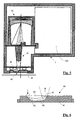
- the spectrophotometer comprises according to the representation of an outer housing 1, in which all mechanical, optical and electrical components of the spectrophotometer are housed.
- the housing 1 has at its (in the drawing) lower end an opening 1a, through which the measuring beam path passes during operation (FIG. 1). Outside the operation, the opening 1a is closed by a light reference arrangement 40 which simultaneously functions as a shutter (FIG. 5).
- the measurement plane in which a measured object O to be measured is in practical operation is denoted by M.
- the components of the spectrophotometer are a lighting arrangement 10 for illuminating the measuring object O located in the measuring plane M at an angle of incidence of substantially 45 °, an picking arrangement 20 for collecting the measuring light remitted by the measuring object O at an angle of departure of substantially 0 ° relative to the solder the measuring plane M, a spectrometer array 30 for the spectral splitting of the collected by the Aufpickanssen 20 and fed through an entrance slit 31 measuring light, provided within the spectrometer assembly 30, acted upon by the spectrally split measuring light photoelectric receiver assembly 32 for converting the individual spectral components of the measuring light into corresponding electrical Signals and an electronic circuit 100, which controls the lighting assembly 10 and from the electric signals generated by the photoelectric receiver assembly 32 digital measurements (spectral data, color data, color Oftenffle etc.) forms and provides a non-illustrated digital interface for further use.
- a first important aspect of the invention relates to the conception of the illumination arrangement 10.
- This comprises a light source 11 designed as a cosine radiator, which is understood to mean a light source which emits non-directionally, ie with a cosinusoidal scattering lobe in forward spatial directions.
- Fig. 3 illustrates this.
- the central or main beam direction of the light source 11 is denoted by 12 in FIG. 3 and is normally perpendicular to the plane of the flat light source 11.
- the light source 11 is preferably implemented by one or more light-emitting diodes 11a-11d, as best seen in FIG. If only one light-emitting diode or several identical light-emitting diodes is / are used, it is best uses a "white" radiating type covering all the spectral range required for the spectral measurements. Preferably, however, a combination of one or more "white” LEDs is used with one or more light emitting diodes of different spectral characteristics, which complement each other with respect to the spectral range to be covered. The same effect can also be achieved by a combination of several different, essentially monochromatic LEDs.
- the light source 11 may also include a UV light emitting diode, which can be switched on separately as needed.
- the (“naked”) light-emitting diodes of the light source 11 are mounted on a common support (chip) 13, as can be seen from FIG.
- This support 13 is preferably made of a highly thermally conductive material and is seated on a printed circuit board 15.
- This is mounted on a metal plate 14, which is arranged in the lower part of the housing 1 parallel to the measuring plane M and at the same time as a cooling surface for the light source 11 and they forming light emitting diodes 11a-11d is used.
- the metal plate 14 is provided to increase the effective cooling surface with side wall portions 14 a, which lie on the surface of the housing 1 and improve the heat dissipation.
- the light source 11 is connected via not shown electrical lines to the electronic circuit 100 and is controlled by this, whereby a selective control of the individual light-emitting diodes 11a-11d may be provided.
- the flat light source 11 is "flat", that is mounted with its flat side parallel to the measuring plane M (or perpendicular to the optical axis of the picking arrangement 20), so that the central or main beam direction 12 is also perpendicular to the measuring plane M.
- the light source 11 is further arranged on the metal plate 14 such that the center distance r of the light source 11 from the main beam 21 of the reflected measuring light (optical axis) is substantially the same as the distance t of the light source 11 from the measuring plane M.
- the measuring spot MF in Therefore, the measuring plane M is acted upon only by the light component which is radiated by the light source 11 substantially at 45 ° in the direction of the measuring spot, namely at an angle of incidence of substantially 45 ° in accordance with the standard.
- the design of the light source 11 as a cosine emitter and its aforementioned "flat" orientation not all the light is used for the illumination of the measuring spot, but this is Lighting concept within the usual accuracy requirements relatively insensitive to variations in the distance of the measurement object from the light source. Another important advantage is that for the lighting assembly 10 only a few components are required and they can be mounted very easily and uncritically. Light-emitting diodes also have the advantage of great robustness and longevity, which contributes to the serviceability of the spectrophotometer.
- a plurality of light sources 11 can also be provided, these then being distributed along a circle around the optical axis 21 of the picking arrangement 20.
- multiple light sources and their spectral characteristics can be chosen differently.
- the Aufpickan eleven 20 has the task to absorb the remitted by the measuring object O measuring light under a standard angle of incidence of substantially 0 ° relative to the perpendicular to the measuring plane M and to lead into the entrance slit 31 of the spectrometer assembly 30.
- the Aufpickan eleven 20 is formed as a one-piece transparent plastic body having a convexly curved entrance surface 22 and coaxially thereto a substantially cylindrical Lichtleitstab 23 and also a coaxial conical mounting tube 24.
- the mounting tube 24 has no optical function, it serves to reduce stray light and to attach the Aufpickan Aunt to the stationary held in the housing 1 printed circuit board 33. Instead of the mounting tube 24 could possibly also be provided spreading or similar fastening means.
- the convexly curved entry face 22 of the picking arrangement acts as a lens, which images the measuring spot MF into the entry face 23a of the light guide rod 23 (FIG. 3).
- the dimension of the entrance surface 23a of the light guide rod 23 and the imaging scale of the lens formed by the entrance surface 22 define the dimension of the measuring spot MF effectively "seen” by the picking assembly 20 (typically about 4 mm ⁇ ).
- the lighting arrangement 10 acts on it a larger area of the test object beyond the measuring spot MF ("over-illumination").
- the light guide rod 23 acts as an integrator over the entire surface of the measuring spot MF and thus compensates for inhomogeneities. It passes the picked-up and fed into him measuring light into the entrance slit 31 of the spectrometer 30. He is the output side slightly bevelled to achieve the required in the spectrometer assembly for optimal illumination slight deflection of the measuring light from the optical axis.
- the picking arrangement 20 preferably consists of a single, easily e.g. Injection molded component that can be easily mounted in the spectrophotometer. It limits the measuring spot and compensates for inhomogeneities, so that no requirements are placed on the lighting arrangement in this respect, and this in turn can be realized very simply.
- Another important aspect of the invention relates to the design of the spectrometer arrangement 30.
- This conventionally comprises a light-tight spectrometer housing 34, the only opening of which is the already mentioned entrance slit 31.
- a concave diffraction grating 35 and the also already mentioned photoelectric receiver assembly 32 which typically consists of a photodiode array with, for example 128 individual photodiodes and is mounted on the printed circuit board 33 already mentioned.
- the measuring light collected by the picking arrangement 20 and introduced into the spectrometer arrangement 30 through the entrance slit 31 is incident on the diffraction grating 35 and is split by the latter into its spectral components.
- the spectrally split measuring light acts on the photoelectric receiver arrangement 32 and is converted by the latter into corresponding electrical signals, wherein a different spectral component can be tapped off at each individual photodiode.
- the photoelectric receiver array is placed at the location of the first order diffraction for this purpose.
- the electrical signals generated by the individual photodiodes of the photoelectric receiver array 32 are supplied via lines of the electronic circuit 100, not shown, where they are processed and digitized in a conventional manner and to the required digital readings (spectral readings, color readings, color density readings, etc.).
- the spectrometer housing 34 is cup-shaped and comprises a substantially cylindrical shell 34a and a lid 34b detachably mounted thereon.
- an annular shoulder 34c is provided, on which the diffraction grating 35 rests with its edge.
- the annular shoulder 34c is formed spherically opposite to the concave edge of the diffraction grating 35, so that there is a clean support.
- a compression spring 36 is located between the lid 34b and the diffraction grating 35 there is a small cavity in which a compression spring 36 is located. This is supported on the inside of the lid 34b and presses the diffraction grating with a defined constant force against the annular shoulder 34c.
- the diffraction grating 35 is arranged coaxially with the casing 34a.
- the latter implies that the entrance slit 31 is outside the optical axis of the diffraction grating 35 and the measuring light beam emerging from the entrance slit 31 is slightly inclined to the optical axis.
- the photoelectric receiver array 32 must be disposed on the same side of the optical axis of the diffraction grating 35 as the entrance slit.
- the optical axis of the pickup arrangement 20 is thus offset somewhat from the optical axis of the diffraction grating 35.
- the pot-shaped spectrometer housing 34 is seated on the already mentioned printed circuit board 33 and is light-tightly closed by this on its underside opposite the cover 34b.
- the entrance slit 31 is either formed by a corresponding slot in the printed circuit board 33 or, as shown, is preferably implemented by a separate nip element mounted on the printed circuit board 33 via a mating passage opening therein.
- On the inside of the jacket 34a downwardly projecting pins 34d are formed, which protrude into corresponding recesses 33d in the printed circuit board 33.
- the pins 34 d and the recesses 33 d form cooperating complementary positioning members, which center the spectrometer housing 34 on the printed circuit board 33.
- a pair of cooperating positioning members are designed as a fixed bearing, the other as plain bearings.
- the line connecting the fixed and sliding bearings is perpendicular to the dispersion direction of the spectrometer (visible in FIG. 4) and remains in the event of temperature fluctuations, ie with different dimensions of the spectrometer (spectrometer housing) and diffraction grating) and printed circuit board (ceramic with a low coefficient of thermal expansion) unaltered.
- the line position and direction is, as in the EP-A 1 041 372 described, so determined that at a z. B. due to temperature increase Wämeausausse of the spectrometer, the grid and the printed circuit board, the position of the spectrum on the detector 32 does not change.
- the spectrometer is thus isothermalized by the correct choice of the position of the two positioning organs.
- the spectrometer housing 34 is held on the printed circuit board 33 by means of a tension spring 37, which on the one hand engages over the cover 34b and on the other hand engages behind the printed circuit board 33, as can be seen in FIG.
- the tension spring 37 By the tension spring 37, the cover 34b is also held on the jacket 34a of the spectrometer housing 34 at the same time. Since the spectrometer is not firmly connected to the printed circuit board, but is pressed only with a defined force on the printed circuit board, the spectrometer and the printed circuit board can freely thermally expand unhindered differently, the spectrometer can slide on the very smooth surface of the ceramic printed circuit board.
- the illustrated configuration of the spectrometer assembly 30 allows for extremely easy fabrication (e.g., as plastic injection molded parts) and, in particular, requires no adjustment.
- the printed circuit board 33 is preferably made of a ceramic material and is thus subjected to small and defined thermally induced dimensional changes (expansion). The positioning of all critical parts is based exclusively on the printed circuit board 33 and can be easily ensured by appropriately precisely shaped and arranged positioning aids on the printed circuit board without subsequent adjustment.
- another photoelectric receiver 38 is arranged in the spectrometer arrangement 30 on the printed circuit board 33 at the location of the zero-order diffraction and likewise connected to the electronic circuit 100.
- This photoreceiver 38 can optionally also be equipped with a conversion filter, which allows the measurement in metric data (eg Lux).
- any not or not perfectly isothermalised spectrometer has some spectral drift due to material properties (thermal expansion, humidity). This drift can be computationally compensated in a manner known per se by means of a spectrally stable reference light source.
- a narrow-band light-emitting diode in conjunction with a temperature-stable dichroic filter is used as the reference light source.
- the coupling of the reference light can be done in various ways. The easiest way to realize the reference light source as an additional measuring light source, the reference light is introduced in this case via the light reference arrangement in the spectrometer.
- the reference light source is located within the spectrometer housing near the entrance slit 31.
- a further photoreceiver 50 is arranged on the metal plate 14 with respect to the optical axis 21 of the picking arrangement symmetrically with respect to the light source 11, which receives the measuring light reflected by the test object at a standard angle of incidence of substantially 45 °.
- this photoreceptor 50 is connected to the electronic circuit 100.
- a filter can be used, which can determine the spectrum of the observed gloss.
- the light reference arrangement 40 already mentioned above is provided, which is arranged at a relatively large distance of typically about 2 mm above the measuring plane M.
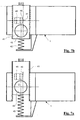
- the light reference arrangement consists essentially of a carriage 41 which is displaceable in the opening 1 a of the outer housing 1 transversely to the optical axis 21 of the picking arrangement 20 between a measuring position and a reference position, as shown in the two figures 7a (measuring position) and 7b (reference position ) can be seen.
- the displacement into the reference position is effected for example by an external, not shown here drive member against the force of a spring 42 which holds the carriage 41 in the measuring position or moved back to the measuring position when the external force is removed.
- the outer Drive member may be provided for example in the device in which the spectrophotometer is used as a built-in device.
- the carriage 41 is provided with a circular passage opening 43, the center of which lies in the measuring position of the carriage 41 substantially in the optical axis 21 of the picking arrangement 20 (FIG. 7a).
- the passage opening 43 is dimensioned sufficiently large so that the illumination light and the measurement light remitted by the measurement object can pass unhindered (FIG. 1).
- the carriage 41 on its upper side a cavity 44 which is bounded laterally by two deflecting mirrors 45 and 46.
- a weakening element 47 e.g. arranged in the form of a diffuser or a gray filter.
- the cavity 44 is laterally offset with respect to the passage opening 43 and in the direction of displacement of the carriage 41.
- the attenuator 47 serves to compensate for the intensity ratios of the measurement on the paper white to the bright measurement.
- the entire cavity 44 may be formed of an optically diffusing plastic. The light scattered over the two 45 ° inclined surfaces in the pickup optics is detected in this case during the bright measurement.
- the described light measurements are relative measurements of the combination of spectral LED brightnesses, sensor sensitivity, etc.
- At minimum in the production of the sensor is an absolute white calibration of the entire system according to standard required.
- the spectrophotometer when the slide 41 is in the reference position, the spectrophotometer is closed to the outside.
- the light reference arrangement 40 thus also functions simultaneously as a mechanical and optical shutter (the latter, for example, for dark measurements).
- the described design of the light reference arrangement 40 this is also protected against contamination.
- the clearance between the spectrophotometer and the measurement object is maintained and the light reference arrangement is accommodated within the built-in space of the spectrophotometer.
- the main functional elements of the electronic circuit 100 of the spectrophotometer are shown in block schematic form.
- the circuit comprises an amplifier and level converter stage 103, an A / D converter 104, a buffer memory 105, a microcontroller 106 and a lamp driver 107, and a serial number memory 108.
- the photoelectric receiver array 32 has its signal outputs to the amplifiers and level converter stage 103 connected.
- the lamp driver 107 feeds the light emitting diodes of the light source 11. If the spectrophotometer, as described above, is equipped with additional photoreceptors or additional light sources, these are involved in a similar manner circuitry.
- the control of the individual functional elements and the functional sequences is performed by the software stored in the microcontroller 106.
- the electronic circuit is state-of-the-art in its basic structure and mode of operation (see, for example, the already mentioned spectrophotometer "i1") and therefore does not require any further explanation by the person skilled in the art.
- a stable light source is of paramount importance. In a conventional lighting with a light bulb as the light source, this problem can be relatively easily solved, inter alia, by a stable power supply.
- a stable power supply if light-emitting diodes are used as light sources, the stability itself is often insufficient for a short time. For stable conditions, it is necessary that the LEDs are operated at a constant current and temperature. The latter is very difficult because the temperature of a light-emitting diode can not be readily measured, for example, with a temperature sensor.
- the duty cycle of the LED is increased slightly during the actual measurement operation of the spectrophotometer, whereby the temperature rises again. Conversely, if the temperature rises, the duty cycle per measurement is lowered slightly or the interval between two consecutive measurements is slightly longer. In this way, the temperature of the light emitting diode can be kept relatively simple constant. In particular, virtually no additional circuitry is required since, with the exception of the simple measuring current source, all required components (A / D converter, lamp driver, microprocessor) are present in any case in a modern digital spectrophotometer (see the above description of the electronic circuit 100).
- the temperature of only that light-emitting diode that provides the greatest contribution to light is conveniently measured.
- the voltage and thus the temperature can be measured at each light emitting diode.
- FIG. 9 shows a basic circuit diagram of a suitable control circuit 110.
- This comprises a switchable operating constant current source 111, a constant current measuring source 112, a changeover switch 113, an A / D converter 114 and a microcontroller 115.
- the microcontroller controls the operating constant current source 111 and the changeover switch 113.
- the A / D converter 114 is located at the anode of the light-emitting diode to be controlled 116 and detects the flow rate voltage when the light-emitting diode 116 is connected via the switch 113 to the measuring constant current source 112.
- the microcontroller 115 calculates the required switch-on or pause time for the light-emitting diode 116 on the basis of the detected flow-through voltage and controls the operating constant current source 111 accordingly. As can be seen, with the exception of the measurement constant current source 112, all components of the control circuit 110 are already in the electronic circuit 100 available. Essentially, only the software of the microcontroller needs to be expanded accordingly.
- the spectral measurement data can alternatively be temperature-corrected accordingly.
- a reference spectrum is measured and stored at each measured temperature. The measured values can be corrected later with these reference spectra.
- this approach requires a significantly higher storage and computational effort, but charged for the LEDs a little less.
- the spectrophotometer according to the invention can be realized in a very compact and cost-effective manner and is particularly suitable for use in inkjet printers (from simple office models to very large formats), dye sublimation printers, color copying machines and also other production machines, where color is a quality-determining feature , eg in printing machines, suitable. It can be used there for all measurement tasks in which spectral, color and density measurement data must be determined. The measurement data obtained can then be evaluated for the most varied tasks, in particular also the characterization of the printers mentioned at the outset.
Landscapes
- Physics & Mathematics (AREA)
- Spectroscopy & Molecular Physics (AREA)
- General Physics & Mathematics (AREA)
- Spectrometry And Color Measurement (AREA)
Claims (23)
- Tête de mesure pour un photomètre spectral, avec un dispositif d'éclairage (10) présentant une source lumineuse (11) de surface pour l'éclairage d'un objet à mesurer (O) se trouvant dans un plan de mesure (M) sous un angle d'incidence de sensiblement 45°, avec un dispositif de prélévement (20) pour intercepter la lumière de mesure réfléchie par l'objet à mesurer sous un angle de réflexion de sensiblement 0° par rapport à la perpendiculaire au plan de mesure, avec un dispositif de spectromètre (30) présentant une fente d'entrée (31) pour la décomposition spectrale de la lumière de mesure interceptée et qui lui est amenée par la fente d'entrée (31) et avec un dispositif récepteur (32) photoélectrique atteint par la lumière de mesure décomposée au plan spectral pour la conversion des parties spectrales individuelles de la lumière de mesure en signaux électriques appropriés, caractérisée en ce que la au moins une source lumineuse (11) de surface est conçue comme un émetteur cosinus et est disposée de telle sorte que la direction du rayonnement principal (12), perpendiculaire au plan de la source lumineuse (11) de surface, de l'émetteur cosinus (11) est parallèle au faisceau principal (21) de la lumière de mesure réfléchie et l'entraxe de l'émetteur cosinus (11) au faisceau principal de la lumière de mesure réfléchie est sensiblement égal à la distance (t) de l'émetteur cosinus (11) au plan médian (M).
- Photomètre spectral avec une tête de mesure selon la revendication 1, qui présente également : un circuit électronique (100) qui commande la source lumineuse (11) et forme des valeurs mesurées numériques à partir des signaux électriques générés par le dispositif récepteur (32) photoélectrique.
- Photomètre spectral selon la revendication 2, caractérisé en ce que la source lumineuse (11) comprend une combinaison de deux ou plus de deux diodes électroluminescentes (11a-d), disposées dans un plan et de préférence sur un support (13) commun, de différentes caractéristiques spectrales, le plan étant orienté sensiblement parallèlement au plan de mesure (M).
- Photomètre spectral selon l'une des revendications 2 ou 3, caractérisé en ce que le dispositif de prélèvement (20) présente une lentille (22) et une barre d'intégrateur (23), la lentille donnant l'image d'un spot de mesure (MF) limité dans le plan de mesure (M) sur la surface d'entrée (23a) de la barre d'intégrateur (23) et la barre d'intégrateur intégrant la lumière de mesure par le spot de mesure (MF) et la dirigeant dans la fente d'entrée (31) du dispositif de spectromètre (30).
- Photomètre spectral selon la revendication 4, caractérisé en ce que la lentille (22) et la barre d'intégrateur (23) sont réalisées d'une seule pièce.
- Photomètre spectral selon l'une des revendications 2 à 5, caractérisé en ce qu'il présente un dispositif de référence claire (40) pouvant être introduit dans la trajectoire de faisceau entre le dispositif d'éclairage (10) et le dispositif de prélèvement (20), pouvant être enlevé à nouveau et se trouvant à une distance relativement grande du plan de mesure (M), qui réfléchit au moins une partie de la lumière d'éclairage dans le dispositif de prélèvement (20).
- Photomètre spectral selon la revendication 6, caractérisé en ce que le dispositif de référence claire (40) est formé par des miroirs de déviation (45, 46) et au moins un élément d'affaiblissement (47).
- Photomètre spectral selon la revendication 6, caractérisé en ce que le dispositif de référence claire (40) est formé par des surfaces à dispersion diffuse.
- Photomètre spectral selon l'une des revendications 6 à 8, caractérisé en ce que le dispositif de référence claire (40) est conçu comme une fermeture.
- Photomètre spectral selon l'une des revendications 2 à 9, caractérisé en ce que le dispositif de spectromètre (30) présente un boîtier de spectromètre (34) sensiblement en forme de pot avec une enveloppe (34a) sensiblement cylindrique et un couvercle (34b) amovible, en ce qu'un réseau de réfraction (35) concave est disposé de façon coaxiale par rapport à l'enveloppe (34a) dans le boîtier de spectromètre et repose sur un épaulement annulaire (34c) réalisé sur l'enveloppe (34a) et formé de préférence de façon complémentaire au réseau de diffraction, et en ce que le couvercle (34b) presse le réseau de diffraction (35) par un ressort de compression (36) avec une force définie contre l'épaulement annulaire (34c).
- Photomètre spectral selon la revendication 8, caractérisé en ce que le boîtier de spectromètre (34) est positionné avec son côté opposé au couvercle (34b) sur une plaque d'impression (33) contenant la fente d'entrée (31) et contenant le dispositif récepteur (32) photoélectrique et est obturé par cette plaque.
- Photomètre spectral selon la revendication 9, caractérisé en ce que l'enveloppe (34a) du boîtier de spectromètre (34) est équipée d'organes de positionnement (34d) qui s'engagent dans des organes de positionnement (33d) complémentaires réalisés sur la plaque d'impression (33).
- Photomètre spectral selon l'une des revendications 11 à 12, caractérisé en ce qu'un ressort de tension (37) est prévu, lequel fixe d'une part le couvercle (34d) sur l'enveloppe (34a) du boîtier de spectromètre (34) et d'autre part maintient le boîtier de spectromètre (34) sur la plaque d'impression (33).
- Photomètre spectral selon l'une des revendications 10 à 13, caractérisé en ce qu'il est athermalisé.
- Photomètre spectral selon l'une des revendications 10 à 13, caractérisé en ce que le boîtier de spectromètre (34) et le réseau de diffraction (35) se trouvant à l'intérieur sont réalisés à base de matériau présentant le même coefficient de dilatation thermique, de sorte que des déplacements relatifs provoqués par une dilatation thermique différente ne peuvent intervenir qu'entre le boîtier de spectromètre (34) en tant que tout et la plaque d'impression (33).
- Photomètre spectral selon l'une des revendications 8 à 11, caractérisé en ce que la fente d'entrée (31) et le dispositif récepteur (32) photoélectrique sont disposés de façon excentrée sur le même côté à l'extérieur de l'axe optique du réseau de diffraction (35).
- Photomètre spectral selon l'une des revendications 8 à 12, caractérisé en ce qu'un récepteur (38) photoélectrique supplémentaire est prévu et disposé dans le boîtier de spectromètre (34) de telle sorte qu'il est atteint par le réseau de diffraction (35) avec lumière de mesure d'ordre zéro.
- Photomètre spectral selon l'une des revendications 9 à 13, caractérisé en ce que le dispositif de prélèvement (20) est monté directement sur le côté, opposé au boîtier de spectromètre (34), de la plaque d'impression (33).
- Photomètre spectral selon l'une des revendications 8 à 14, caractérisé en ce que le boîtier de spectromètre (34) et le réseau de diffraction (35) sont réalisés dans la même matière plastique et sont fabriqués de préférence par un procédé de moulage par injection.
- Photomètre spectral selon l'une des revendications 2 à 19, caractérisé en ce qu'il est prévu un autre récepteur (50) photoélectrique, disposé en symétrie axiale de la source lumineuse (11) par rapport au faisceau principal (21) du dispositif de prélèvement (20), qui reçoit de la lumière directement réfléchie par l'objet à mesurer sous un angle d'incidence de sensiblement 45°.
- Photomètre spectral selon l'une des revendications 2 à 20, caractérisé en ce qu'une régulation (110) pour maintenir constante la température de la source de lumière (11) est présente.
- Photomètre spectral selon la revendication 3 ou 17, caractérisé en ce que la régulation (110) détermine comme critère de la température de la (des) diode(s) contenue(s) dans la source lumineuse (11) sa tension de passage avec un courant de mesure constant beaucoup plus faible par rapport au courant de service normal.
- Photomètre spectral selon la revendication 18, caractérisé en ce que la régulation (110) règle la température des diodes électroluminescentes par variation de la durée de mise en circuit et de mise hors circuit en fonction de la tension de passage déterminée.
Priority Applications (3)
| Application Number | Priority Date | Filing Date | Title |
|---|---|---|---|
| DE50307469T DE50307469D1 (de) | 2003-07-23 | 2003-07-23 | Spektralfotometer und zugehöriger Messkopf |
| EP03016535A EP1507134B1 (fr) | 2003-07-23 | 2003-07-23 | Spectrophotomètre et tête de mesure correspondante |
| US10/894,797 US7365843B2 (en) | 2003-07-23 | 2004-07-20 | Spectral photometer and associated measuring head |
Applications Claiming Priority (1)
| Application Number | Priority Date | Filing Date | Title |
|---|---|---|---|
| EP03016535A EP1507134B1 (fr) | 2003-07-23 | 2003-07-23 | Spectrophotomètre et tête de mesure correspondante |
Publications (2)
| Publication Number | Publication Date |
|---|---|
| EP1507134A1 EP1507134A1 (fr) | 2005-02-16 |
| EP1507134B1 true EP1507134B1 (fr) | 2007-06-13 |
Family
ID=33560761
Family Applications (1)
| Application Number | Title | Priority Date | Filing Date |
|---|---|---|---|
| EP03016535A Expired - Lifetime EP1507134B1 (fr) | 2003-07-23 | 2003-07-23 | Spectrophotomètre et tête de mesure correspondante |
Country Status (3)
| Country | Link |
|---|---|
| US (1) | US7365843B2 (fr) |
| EP (1) | EP1507134B1 (fr) |
| DE (1) | DE50307469D1 (fr) |
Families Citing this family (28)
| Publication number | Priority date | Publication date | Assignee | Title |
|---|---|---|---|---|
| EP1694049B1 (fr) | 2005-02-16 | 2009-07-01 | X-Rite Europe GmbH | Colorimètre et tête de mesure associée |
| EP1694047B1 (fr) | 2005-02-16 | 2020-03-18 | X-Rite Switzerland GmbH | Dispositif d'éclairage destiné à un colorimètre |
| EP1694048B1 (fr) | 2005-02-16 | 2013-01-09 | X-Rite Europe GmbH | Colorimètre et procédé de mesure destiné à celui-ci |
| US20100239436A1 (en) * | 2005-05-17 | 2010-09-23 | Honeywell International Inc. | A thermal pump |
| JP2007085963A (ja) * | 2005-09-26 | 2007-04-05 | Fuji Xerox Co Ltd | 光学測定装置及びこれを用いた画像形成装置 |
| DE102007038752A1 (de) * | 2007-08-16 | 2009-02-19 | Giesecke & Devrient Gmbh | Verfahren für die Kalibrierung eines Sensorsystems |
| DE102007053574B4 (de) | 2007-11-09 | 2019-05-02 | Byk Gardner Gmbh | Farbmessgerät |
| DE102008028689A1 (de) * | 2008-06-17 | 2009-12-24 | Giesecke & Devrient Gmbh | Sensoreinrichtung zur spektral aufgelösten Erfassung von Wertdokumenten und ein diese betreffendes Verfahren |
| JP2010281808A (ja) * | 2009-05-01 | 2010-12-16 | Konica Minolta Sensing Inc | 照明装置およびそれを用いる反射特性測定装置 |
| US8179531B2 (en) * | 2009-06-17 | 2012-05-15 | Hewlett-Packard Development Company, L.P. | Shuttering and sealing device |
| EP2270450B1 (fr) * | 2009-06-24 | 2011-10-12 | X-Rite Europe GmbH | Dispositif portable de mesure de lumière |
| CN102625917B (zh) | 2009-08-03 | 2016-03-30 | 以操作-试验名义经营的索夫泰克系统配套公司 | 测试高亮度发光二极管(hbled)的系统和方法 |
| WO2011058496A2 (fr) * | 2009-11-16 | 2011-05-19 | Koninklijke Philips Electronics N.V. | Dispositif capteur à diode électroluminescente |
| JP5354098B2 (ja) * | 2010-05-13 | 2013-11-27 | コニカミノルタ株式会社 | 照明光学系、反射特性測定装置及び照明方法 |
| US20120313748A1 (en) * | 2011-06-09 | 2012-12-13 | Pawlik Thomas D | Authentication of a security marker |
| US20120313747A1 (en) * | 2011-06-09 | 2012-12-13 | Pawlik Thomas D | Method for authenticating security markers |
| US20120313749A1 (en) * | 2011-06-09 | 2012-12-13 | Pawlik Thomas D | Authentication of a security marker |
| GB201300362D0 (en) | 2013-01-09 | 2013-02-20 | Reckitt Benckiser Uk Ltd | Low cost senor system |
| CN103398779B (zh) * | 2013-07-11 | 2016-01-20 | 华北水利水电大学 | 一种恒照度透射色敏测量装置 |
| CN103900688A (zh) * | 2014-03-28 | 2014-07-02 | 中国科学院上海技术物理研究所 | 一种基于自由曲面的成像光谱仪分光系统 |
| CN104034419B (zh) * | 2014-05-05 | 2017-04-05 | 中国科学院长春光学精密机械与物理研究所 | 可校正谱线弯曲的成像光谱仪系统及其校正方法 |
| CN105785105B (zh) * | 2016-05-05 | 2018-11-27 | 南京铁道职业技术学院 | 一种三色光差杠杆微电流测量装置 |
| JP6984651B2 (ja) | 2017-03-21 | 2021-12-22 | コニカミノルタ株式会社 | 蛍光増白試料の分光放射特性の測定方法、および、蛍光増白試料の分光放射特性の測定装置 |
| US10935425B2 (en) * | 2017-07-18 | 2021-03-02 | Shimadzu Corporation | Spectroscopic detector |
| CH714677A2 (de) * | 2018-02-23 | 2019-08-30 | Hapa Ag | Aushärtekammer für Druckerzeugnisse. |
| WO2020017118A1 (fr) * | 2018-07-19 | 2020-01-23 | コニカミノルタ株式会社 | Dispositif photométrique |
| EP3819611B1 (fr) * | 2019-11-05 | 2024-03-27 | Hitachi High-Tech Analytical Science GmbH | Spectromètre d'émission optique facilement ajustable |
| WO2025233271A1 (fr) | 2024-05-06 | 2025-11-13 | Trinamix Gmbh | Procédé de détermination continue d'informations de température pour unité d'éclairage |
Family Cites Families (6)
| Publication number | Priority date | Publication date | Assignee | Title |
|---|---|---|---|---|
| US5671059A (en) * | 1995-09-21 | 1997-09-23 | Hewlett-Packard Company | Electroluminescent color device |
| US5963333A (en) * | 1996-09-12 | 1999-10-05 | Color Savvy Systems Limited | Color sensor |
| US6384918B1 (en) * | 1999-11-24 | 2002-05-07 | Xerox Corporation | Spectrophotometer for color printer color control with displacement insensitive optics |
| EP1213569B1 (fr) * | 2000-12-08 | 2006-05-17 | Gretag-Macbeth AG | Dispositif pour la mesure pixel par pixel d'un objet de mesure plat |
| US6633382B2 (en) * | 2001-05-22 | 2003-10-14 | Xerox Corporation | Angular, azimuthal and displacement insensitive spectrophotometer for color printer color control systems |
| EP1314972B1 (fr) * | 2001-11-26 | 2010-07-14 | X-Rite Europe GmbH | Spectrophotomètre et son utilisation |
-
2003
- 2003-07-23 EP EP03016535A patent/EP1507134B1/fr not_active Expired - Lifetime
- 2003-07-23 DE DE50307469T patent/DE50307469D1/de not_active Expired - Lifetime
-
2004
- 2004-07-20 US US10/894,797 patent/US7365843B2/en not_active Expired - Lifetime
Non-Patent Citations (1)
| Title |
|---|
| None * |
Also Published As
| Publication number | Publication date |
|---|---|
| EP1507134A1 (fr) | 2005-02-16 |
| US20050052648A1 (en) | 2005-03-10 |
| US7365843B2 (en) | 2008-04-29 |
| DE50307469D1 (de) | 2007-07-26 |
Similar Documents
| Publication | Publication Date | Title |
|---|---|---|
| EP1507134B1 (fr) | Spectrophotomètre et tête de mesure correspondante | |
| EP1694049B1 (fr) | Colorimètre et tête de mesure associée | |
| EP1314972B1 (fr) | Spectrophotomètre et son utilisation | |
| EP2270450B1 (fr) | Dispositif portable de mesure de lumière | |
| EP1180898B1 (fr) | Méthode et dispositif pour la mesure colorimétrique d'un document bidimensionnel | |
| EP0311561B1 (fr) | Tête de mesure | |
| EP2505973B1 (fr) | Colorimètre manuel | |
| EP2505972B1 (fr) | Colorimètre manuel | |
| DE102004014532B3 (de) | Optisches System zur Erzeugung eines beleuchteten Gebildes | |
| DE102014103640A1 (de) | Vorrichtung und Verfahren zum Untersuchen von Oberflächeneigenschaften | |
| DE3513475C2 (fr) | ||
| EP1694047B1 (fr) | Dispositif d'éclairage destiné à un colorimètre | |
| EP1694048B1 (fr) | Colorimètre et procédé de mesure destiné à celui-ci | |
| EP2513874B1 (fr) | Détecteur pour vérifier des documents de valeur | |
| DE69533802T2 (de) | Abtastkolorimeter | |
| DE112005000972B4 (de) | Farbmessgerät mit parallelen Detektoren | |
| DE10148748A1 (de) | Verfahren und Vorrichtung zum berührungslosen Bestimmen biophysikalischer Parameter von Pflanzenbeständen | |
| EP0359167A2 (fr) | Réfractomètre utilisant une division d'ouverture en dépendance de l'index de réfraction | |
| DE102022128701A1 (de) | Messvorrichtung für abgeschwächte totalreflexion, die zu einer raman-spektralmessung in der lage ist | |
| DE112014005877T5 (de) | Lichtemittierendes Element, Referenzlichtquelle und Verfahren zum Beobachten eines Leuchtkörpers | |
| DE10137043A1 (de) | Vorrichtung zur Untersuchung von Wertdokumenten | |
| DE19939154A1 (de) | Verfahren und Meßvorrichtung zur Druckkontrolle und Bildanalyse | |
| EP2161554A1 (fr) | Dispositif destiné à la mesure d'une distribution spectrale d'un imprimé créé à l'aide d'un dispositif d'impression | |
| DE202009008707U1 (de) | Handlichtmessgerät | |
| DE10148737A1 (de) | Verfahren und Vorrichtung zum berührungslosen Bestimmen biophysikalischer Parameter von Pflanzenbeständen |
Legal Events
| Date | Code | Title | Description |
|---|---|---|---|
| PUAI | Public reference made under article 153(3) epc to a published international application that has entered the european phase |
Free format text: ORIGINAL CODE: 0009012 |
|
| AK | Designated contracting states |
Kind code of ref document: A1 Designated state(s): AT BE BG CH CY CZ DE DK EE ES FI FR GB GR HU IE IT LI LU MC NL PT RO SE SI SK TR |
|
| AX | Request for extension of the european patent |
Extension state: AL LT LV MK |
|
| 17P | Request for examination filed |
Effective date: 20050506 |
|
| 17Q | First examination report despatched |
Effective date: 20050617 |
|
| AKX | Designation fees paid |
Designated state(s): CH DE FR GB IT LI |
|
| GRAP | Despatch of communication of intention to grant a patent |
Free format text: ORIGINAL CODE: EPIDOSNIGR1 |
|
| GRAS | Grant fee paid |
Free format text: ORIGINAL CODE: EPIDOSNIGR3 |
|
| RIN1 | Information on inventor provided before grant (corrected) |
Inventor name: SCHENKEL, PAUL Inventor name: FRICK, BEAT |
|
| GRAA | (expected) grant |
Free format text: ORIGINAL CODE: 0009210 |
|
| AK | Designated contracting states |
Kind code of ref document: B1 Designated state(s): CH DE FR GB IT LI |
|
| REG | Reference to a national code |
Ref country code: GB Ref legal event code: FG4D Free format text: NOT ENGLISH |
|
| REG | Reference to a national code |
Ref country code: CH Ref legal event code: EP |
|
| GBT | Gb: translation of ep patent filed (gb section 77(6)(a)/1977) |
Effective date: 20070613 |
|
| REF | Corresponds to: |
Ref document number: 50307469 Country of ref document: DE Date of ref document: 20070726 Kind code of ref document: P |
|
| ET | Fr: translation filed | ||
| PGFP | Annual fee paid to national office [announced via postgrant information from national office to epo] |
Ref country code: IT Payment date: 20070721 Year of fee payment: 5 |
|
| PLBE | No opposition filed within time limit |
Free format text: ORIGINAL CODE: 0009261 |
|
| STAA | Information on the status of an ep patent application or granted ep patent |
Free format text: STATUS: NO OPPOSITION FILED WITHIN TIME LIMIT |
|
| PGFP | Annual fee paid to national office [announced via postgrant information from national office to epo] |
Ref country code: FR Payment date: 20070710 Year of fee payment: 5 |
|
| 26N | No opposition filed |
Effective date: 20080314 |
|
| REG | Reference to a national code |
Ref country code: CH Ref legal event code: PFA Owner name: X-RITE EUROPE GMBH Free format text: GRETAG-MACBETH AG#ALTHARDSTRASSE 70#8105 REGENSDORF (CH) -TRANSFER TO- X-RITE EUROPE GMBH#ALTHARDSTRASSE 70#8105 REGENSDORF (CH) |
|
| REG | Reference to a national code |
Ref country code: FR Ref legal event code: ST Effective date: 20090331 |
|
| PG25 | Lapsed in a contracting state [announced via postgrant information from national office to epo] |
Ref country code: FR Free format text: LAPSE BECAUSE OF NON-PAYMENT OF DUE FEES Effective date: 20080731 Ref country code: IT Free format text: LAPSE BECAUSE OF NON-PAYMENT OF DUE FEES Effective date: 20080723 |
|
| REG | Reference to a national code |
Ref country code: DE Ref legal event code: R082 Ref document number: 50307469 Country of ref document: DE Representative=s name: SCHWABE SANDMAIR MARX, DE Ref country code: DE Ref legal event code: R081 Ref document number: 50307469 Country of ref document: DE Owner name: X-RITE SWITZERLAND GMBH, CH Free format text: FORMER OWNER: X-RITE EUROPE GMBH, REGENSDORF, CH Ref country code: DE Ref legal event code: R082 Ref document number: 50307469 Country of ref document: DE Representative=s name: SCHWABE SANDMAIR MARX PATENTANWAELTE RECHTSANW, DE |
|
| REG | Reference to a national code |
Ref country code: CH Ref legal event code: PFA Owner name: X-RITE SWITZERLAND GMBH, CH Free format text: FORMER OWNER: X-RITE EUROPE GMBH, CH |
|
| PGFP | Annual fee paid to national office [announced via postgrant information from national office to epo] |
Ref country code: GB Payment date: 20220606 Year of fee payment: 20 |
|
| PGFP | Annual fee paid to national office [announced via postgrant information from national office to epo] |
Ref country code: DE Payment date: 20220531 Year of fee payment: 20 |
|
| PGFP | Annual fee paid to national office [announced via postgrant information from national office to epo] |
Ref country code: CH Payment date: 20220801 Year of fee payment: 20 |
|
| REG | Reference to a national code |
Ref country code: DE Ref legal event code: R071 Ref document number: 50307469 Country of ref document: DE |
|
| REG | Reference to a national code |
Ref country code: CH Ref legal event code: PL |
|
| REG | Reference to a national code |
Ref country code: GB Ref legal event code: PE20 Expiry date: 20230722 |
|
| PG25 | Lapsed in a contracting state [announced via postgrant information from national office to epo] |
Ref country code: GB Free format text: LAPSE BECAUSE OF EXPIRATION OF PROTECTION Effective date: 20230722 |