EP1507284A2 - Vorrichtung und Verfahren zum Indizieren und Abtrennen von Filmstreifen - Google Patents
Vorrichtung und Verfahren zum Indizieren und Abtrennen von Filmstreifen Download PDFInfo
- Publication number
- EP1507284A2 EP1507284A2 EP04077280A EP04077280A EP1507284A2 EP 1507284 A2 EP1507284 A2 EP 1507284A2 EP 04077280 A EP04077280 A EP 04077280A EP 04077280 A EP04077280 A EP 04077280A EP 1507284 A2 EP1507284 A2 EP 1507284A2
- Authority
- EP
- European Patent Office
- Prior art keywords
- film
- feeding device
- indexing
- linear feeding
- trimming
- Prior art date
- Legal status (The legal status is an assumption and is not a legal conclusion. Google has not performed a legal analysis and makes no representation as to the accuracy of the status listed.)
- Withdrawn
Links
Images

Classifications
-
- H—ELECTRICITY
- H10—SEMICONDUCTOR DEVICES; ELECTRIC SOLID-STATE DEVICES NOT OTHERWISE PROVIDED FOR
- H10W—GENERIC PACKAGES, INTERCONNECTIONS, CONNECTORS OR OTHER CONSTRUCTIONAL DETAILS OF DEVICES COVERED BY CLASS H10
- H10W95/00—Packaging processes not covered by the other groups of this subclass
-
- H—ELECTRICITY
- H10—SEMICONDUCTOR DEVICES; ELECTRIC SOLID-STATE DEVICES NOT OTHERWISE PROVIDED FOR
- H10P—GENERIC PROCESSES OR APPARATUS FOR THE MANUFACTURE OR TREATMENT OF DEVICES COVERED BY CLASS H10
- H10P72/00—Handling or holding of wafers, substrates or devices during manufacture or treatment thereof
- H10P72/04—Apparatus for manufacture or treatment
- H10P72/0446—Apparatus for mounting on conductive members, e.g. leadframes or conductors on insulating substrates
-
- H—ELECTRICITY
- H10—SEMICONDUCTOR DEVICES; ELECTRIC SOLID-STATE DEVICES NOT OTHERWISE PROVIDED FOR
- H10P—GENERIC PROCESSES OR APPARATUS FOR THE MANUFACTURE OR TREATMENT OF DEVICES COVERED BY CLASS H10
- H10P72/00—Handling or holding of wafers, substrates or devices during manufacture or treatment thereof
- H10P72/04—Apparatus for manufacture or treatment
- H10P72/0442—Apparatus for placing on an insulating substrate, e.g. tape
-
- H—ELECTRICITY
- H10—SEMICONDUCTOR DEVICES; ELECTRIC SOLID-STATE DEVICES NOT OTHERWISE PROVIDED FOR
- H10W—GENERIC PACKAGES, INTERCONNECTIONS, CONNECTORS OR OTHER CONSTRUCTIONAL DETAILS OF DEVICES COVERED BY CLASS H10
- H10W72/00—Interconnections or connectors in packages
-
- Y—GENERAL TAGGING OF NEW TECHNOLOGICAL DEVELOPMENTS; GENERAL TAGGING OF CROSS-SECTIONAL TECHNOLOGIES SPANNING OVER SEVERAL SECTIONS OF THE IPC; TECHNICAL SUBJECTS COVERED BY FORMER USPC CROSS-REFERENCE ART COLLECTIONS [XRACs] AND DIGESTS
- Y10—TECHNICAL SUBJECTS COVERED BY FORMER USPC
- Y10T—TECHNICAL SUBJECTS COVERED BY FORMER US CLASSIFICATION
- Y10T83/00—Cutting
- Y10T83/04—Processes
-
- Y—GENERAL TAGGING OF NEW TECHNOLOGICAL DEVELOPMENTS; GENERAL TAGGING OF CROSS-SECTIONAL TECHNOLOGIES SPANNING OVER SEVERAL SECTIONS OF THE IPC; TECHNICAL SUBJECTS COVERED BY FORMER USPC CROSS-REFERENCE ART COLLECTIONS [XRACs] AND DIGESTS
- Y10—TECHNICAL SUBJECTS COVERED BY FORMER USPC
- Y10T—TECHNICAL SUBJECTS COVERED BY FORMER US CLASSIFICATION
- Y10T83/00—Cutting
- Y10T83/202—With product handling means
- Y10T83/2066—By fluid current
- Y10T83/207—By suction means
Definitions
- the invention relates to the indexing of a length of film for trimming, and severing the film after it has been indexed, for transfer and placement onto an object surface.
- Stacked dice are becoming more common in the semiconductor manufacturing industry. Its advantage lies in the fact that stacked dice incorporate more silicon functionality by stacking multiple dice into a single package. This reduces overall size by eliminating additional packages on the circuit board. Furthermore, it increases space savings while enhancing electrical performance by reducing propagation time for signals to traverse from one chip to another.
- an adhesive is usually used to stick adjacent dice together.
- adhesive in the form of epoxy is used to serve this function as well as to act as a spacer.
- an adhesive in the form of a film made of an elastomeric material has been introduced. It also serves the function of adhering adjacent dice together and spacing them apart.
- This adhesive film is generally provided in reel form, and an efficient and accurate apparatus and method is required to index and sever such film fed from a reel.
- an apparatus for indexing a length of film for severance comprising: a linear feeding device operative to hold the film and to feed a predetermined amount of film to a trimming device by moving linearly between an initial position and another position towards the trimming device; and a film holder between the linear feeding device and the trimming device that is operable between a first position wherein a gap is provided for the film to pass through during feeding to the trimming device, and a second position for clamping the film when severing the film with the trimming device.
- a method for indexing a length of film for severance at a severance position comprising the steps of: providing a linear feeding device at an initial indexing position for holding the film and a gap between the initial indexing position and the severance position for the film to pass through; feeding a predetermined amount of film for severance at the severance position by moving the linear feeding device together with the film linearly towards the severance position; closing the said gap and clamping the film; then severing the predetermined length of film.
- FIG 1 is a side view illustration of a layout of a prior art film handling apparatus 100 for indexing and severing a roll of adhesive film 104.
- a tape reel 102 is installed on the apparatus 100 and supplies the adhesive film 104 to a fixed platform 108.
- the film 104 is gripped on both its upper and lower surfaces by film rollers 106 on the fixed platform 108.
- the film rollers 106 have frictional surfaces to drive the film forward and serve to control feeding of the film 104 to a movable platform 110.
- the movable platform moves up and down relative to the fixed platform 108 and a trimming support 112.
- a piece of adhesive film 104 is severed when the movable platform 110 engages and overlaps the trimming support 112 during upwards movement of the movable platform 110.
- rollers 106 may result in a conversion error when converting their rotational output to linear output required to index the adhesive film 104.
- a tolerance gap 114 that is maintained between the fixed platform 108 and the trimming support 112 to allow the film 104 to slide to the movable platform 110 during indexing.
- this tolerance gap 114 allows slack in the film and movement of the film 104 during trimming. This causes the film 104 to elongate unnecessarily and may result in an undesirable and extensive burr at a severed edge of the film 104. Burr should be reduced so that trimming accuracy is improved.
- FIG. 2 is an isometric view of a film handling apparatus 10 according to the preferred embodiment of the invention.
- a film reel 12 is installed on an input reel handler in the apparatus 10, providing film 14, such as adhesive film, that is to be severed or trimmed, transferred and placed onto a substrate 16 located on a work holder 17.
- film 14 such as adhesive film
- a linear feeding device is used to index the film 14 for severance.
- the film 14 is extended onto a fixed platform 15 and is generally arranged horizontally on the fixed platform 15 with guiding rollers 18.
- the guiding rollers 18 do not need to actively drive the film 14 for feeding, but serve as guides to keep the film 14 substantially horizontal on the fixed platform 15. It is also preferable that movement of the film 14 be further restricted by passing it through film width guides 20, which keep a path of the film 14 straight.
- the film width guides 20 are preferably adjustable to cater for different widths of film 14.
- the film 14 is further extended past a film holder 22 that is movable to hold the film 14 firmly during trimming, as will be explained in greater detail below.
- a trimming device comprising a trimming support 24 and a movable platform 26.
- the trimming support 24 is located over the film holder 22 and there is a gap between the film holder 22 and trimming support 24 for the film 14 to slide during indexing.
- Adjacent to the film holder 22 is the movable platform 26 that is adapted to move up and down relative to the trimming support 24.
- a linear feeding device in the form of a film feeder 28 is provided.
- the film feeder 28 has a linear driving mechanism that is adapted to move forwards and backwards in a horizontal motion along the surface of the fixed platform 15 from an initial position towards the movable platform 26.
- it comprises a vacuum head coupled to a vacuum suction device. It uses vacuum suction to hold the strip of film 14 and feed a required length of film 14 towards the movable platform 26 during indexing.
- a preferred action is to slide the film feeder 28 along the top surface of the fixed platform 15 supporting the film 14. Thereafter, the vacuum suction is switched off as the film feeder 28 moves back to its initial position after indexing.
- a vacuum head with a patterned interface which may be in the form of a series of patterns, is used for the film feeder 28. This vacuum head patterned interface is changeable for different types of film.
- a linear encoder 30 associated with or coupled to the film feeder 28 may determined a position of the film feeder 28 by relaying positional information of the film feeder 28 to a processor for positional feedback and controlling movement of the film feeder 28. This allows higher accuracy and more precise indexing. It is preferable that the film feeder 28 has a surface that is made of material that has low static generation with the film, such as a Teflon surface 32 to contact the film 14. The Teflon surface 32 assists the film feeder 28 in sliding over the film 14 without pulling the film when the vacuum suction is turned off and it moves towards its initial position.
- an end-of-film sensor 34 located on the fixed platform 15.
- the end-of-film sensor 34 takes advantage of the fact that there is usually a corresponding end-of-film indicator on the film reel, for example, an end-of-film hole 36, to denote an exhaustion of a film reel 12. Therefore, the apparatus 10 is adapted to stop functioning and an alarm may be sounded to request a change of film reel 12 when this happens.
- a film reel 12 that provides adhesive film usually also provides an adhesive film 14 with a protective backing cover 38 on one or both surfaces of the adhesive film 14.
- a peeling device should be included to peel the backing cover 38 off the adhesive film 14 prior to trimming. This may be achieved by coupling backing cover 38 peeled off from the film 14 to a collecting reel 40.
- the protective cover 38 is fed into and collected by the collecting reel 40 located below the fixed platform 15.
- the collecting reel 40 is preferably driven to actively peel the protective cover 38 from the adhesive film 14 as it is fed towards the movable platform 26 for trimming.
- reel collecting sensors 42 placed next to the collecting reel 40 so as to detect when the collecting reel 40 is full and needs to be replaced.
- the reel collecting sensors 42 also indicate when to turn on the collecting reel 40 motor to collect more backing cover 38, since when excess backing cover 38 is separated from the adhesive film 14, it loops closer to and may thus trigger the lower reel collecting sensor 42.
- the apparatus 10 Another feature of the apparatus 10 is that some slack should be maintained in the film 14 between the film reel 12 and the fixed platform 15. To do this, the film 14 is fed as a loop to the fixed platform 15. A pair of reel feeding sensors 44 may be placed facing each other with the film 14 in between to ensure that the loop is maintained. Thus, there is a top sensor and a bottom sensor. The reel feeding sensors 44 may be positioned such that at particular positions of the film 14 leaving the film reel 12, for example if the film 14 is too close to the top sensor 44, the apparatus 10 will generate more film 14 from the film reel 12. Conversely, if the film 14 is too close to the bottom sensor 44, the apparatus 10 will stop generating film 14 from the film reel 12.
- a film sensor 46 is located on the movable platform 26 for determining the presence or absence of film 14 on the trimming device. Movement of the movable platform 26 to sever a piece of film 14 may be predicated upon the film sensor 46 sensing the presence of film 14 on it before a trimming action is initiated.
- a pick-up tool 50 is moved over the piece of film 14, and picks up the film by suitable means, such as by vacuum suction.
- the pick-up tool carries the film 14 over an optical device such as a film inspection camera 52 located between the movable platform 26 and a placement position.
- the pick-up tool 50 holds the piece of film on one surface while an opposite surface of the piece of film is inspected.
- an image captured by the film inspection camera 52 is processed by an image processor to determine, in particular, whether it is of a correct shape and/or size for attachment to the substrate 16.
- the piece of film 14 If the piece of film 14 is acceptable, it will be carried over to a bonding position of the substrate 16 and be attached. An indexing camera 56 is located over the substrate 16 and bonding position to ensure that the piece of film 14 is correctly placed. If, during inspection by the film inspection camera 52, the piece of film 14 is found to be defective or otherwise does not qualify acceptability criteria, it will instead be dropped into a waste collecting bin 54.
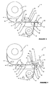
- Figure 3 is a side view illustration of the layout of the apparatus 10 of figure 2 that is indexing a length of film 14 for trimming.
- a vacuum device 29 of the film feeder 28 is turned on, and the length of film 14 is held by the film feeder 28. From its initial position, the film feeder 28 will move towards the movable platform 26 bringing the film 14 with it. There is a tolerance gap 25 between the film holder 22 and the trimming support 24 to allow the film 14 to pass through the gap 25.
- the linear encoder 30 indicates when an end of an indexing position is reached so that the film feeder 28 stops and the vacuum device 29 is switched off. There should now be an appropriate length of film 14 over the movable platform 26 for trimming.
- the collecting reel 40 may be driven to peel off protective backing cover 38 from the film 14.
- Figure 4 is a side view illustration of the layout of the apparatus 10 showing a trimming motion of its trimming device.
- the film holder 22 is located between the film feeder 28 and the movable platform 26, and is operable between a first position wherein a gap is provided for the film 14 to pass through during feeding to the movable platform 26 and a second position from clamping the film 14 when severing the film 14.
- the film holder 22 moves up to clamp the film 14 between the film holder 22 and the trimming support 24.
- the movable platform 26 engages the trimming support 24 and overlaps it, as shown in figure 4. Movement of the film holder 22 and movable platform 26 may be synchronized so that they move up together, or movement may be successive. In either case, the tolerance gap 25 is closed during trimming.
- the interaction between the movable platform 26 and trimming support 24 severs a piece of film 14 for pick-up and attachment by the pick-up tool 50.
- the film edge is held firmly and is elongated during trimming for a shorter time. This helps to reduce the burr length of the film edge. There is no movement along any direction and less distortion is found at a corner of the film during trimming since the film 14 is held firmly.
- the film feeder 28 is moved back horizontally to its initial position.
- the Teflon surface 32 of the film feeder 28 assists it in moving backwards without pulling on the film 14.
- the film holder 22 is still holding onto the film 14 as the film feeder 28 moves backwards to get ready for the next indexing cycle of the film 14.
- misalignment of the film 14 is avoided during backwards movement of the film feeder 28.
- the film holder 22 is moved down again to leave a tolerance gap 25 for a further length of film 14 to be fed in the next indexing cycle.
Landscapes
- Labeling Devices (AREA)
- Auxiliary Devices For And Details Of Packaging Control (AREA)
- Controlling Sheets Or Webs (AREA)
- Advancing Webs (AREA)
Applications Claiming Priority (2)
| Application Number | Priority Date | Filing Date | Title |
|---|---|---|---|
| US642835 | 2003-08-14 | ||
| US10/642,835 US20050034577A1 (en) | 2003-08-14 | 2003-08-14 | Apparatus and method for indexing and severing film |
Publications (2)
| Publication Number | Publication Date |
|---|---|
| EP1507284A2 true EP1507284A2 (de) | 2005-02-16 |
| EP1507284A3 EP1507284A3 (de) | 2006-01-04 |
Family
ID=33565296
Family Applications (1)
| Application Number | Title | Priority Date | Filing Date |
|---|---|---|---|
| EP20040077280 Withdrawn EP1507284A3 (de) | 2003-08-14 | 2004-08-12 | Vorrichtung und Verfahren zum Indizieren und Abtrennen von Filmstreifen |
Country Status (6)
| Country | Link |
|---|---|
| US (1) | US20050034577A1 (de) |
| EP (1) | EP1507284A3 (de) |
| JP (1) | JP2005060114A (de) |
| KR (1) | KR100653571B1 (de) |
| SG (2) | SG109554A1 (de) |
| TW (1) | TWI267955B (de) |
Cited By (1)
| Publication number | Priority date | Publication date | Assignee | Title |
|---|---|---|---|---|
| CN108100710A (zh) * | 2017-12-04 | 2018-06-01 | 东莞市优速机械有限公司 | 一种安全带的激光切带装置 |
Families Citing this family (4)
| Publication number | Priority date | Publication date | Assignee | Title |
|---|---|---|---|---|
| US8262962B2 (en) * | 2007-04-26 | 2012-09-11 | Kwangwoo Michael Ko | Die-cut and method of manufacturing or assembling die-cuts from the components thereof |
| CN114080149A (zh) * | 2020-08-20 | 2022-02-22 | 三赢科技(深圳)有限公司 | 剥离装置 |
| CN220363584U (zh) * | 2023-07-28 | 2024-01-19 | 上海凯虹科技电子有限公司 | 一种器件拆卸装置 |
| TW202536332A (zh) * | 2024-03-12 | 2025-09-16 | 聖傑機器工業股份有限公司 | 具有視覺辨識功能之鋸切裝置 |
Family Cites Families (42)
| Publication number | Priority date | Publication date | Assignee | Title |
|---|---|---|---|---|
| US1085356A (en) * | 1912-02-02 | 1914-01-27 | Paper Working Machines Co | Cutting mechanism. |
| US1658989A (en) * | 1924-10-13 | 1928-02-14 | Package Service Corp | Tape-dispensing machine or the like |
| US2214478A (en) * | 1937-12-22 | 1940-09-10 | Rose Patch & Label Company | Label cutting and packing machine |
| US2657926A (en) * | 1948-03-11 | 1953-11-03 | Electrolux Corp | Tape dispenser |
| US3756899A (en) * | 1968-02-12 | 1973-09-04 | New Jersey Machine Corp | System of label verification control and product accountability |
| CH512974A (de) * | 1969-02-26 | 1971-09-30 | Arx Paul Von | Vorrichtung an Tafelschere zum Schneiden nach Markierungen, unter ständiger Beobachtung des Schnittes |
| US3648552A (en) * | 1970-07-17 | 1972-03-14 | Harris Intertype Corp | Fluidic control for material cutter |
| SE348402B (de) * | 1971-09-14 | 1972-09-04 | Gislaved Ab Gummifab | |
| US3829346A (en) * | 1972-12-12 | 1974-08-13 | D Sullivan | Tape applicator |
| JPS5356594A (en) * | 1976-07-14 | 1978-05-23 | Shinko Sangyo Trading | Device for cutting at specific length and supplying adhesive tape |
| US4265385A (en) * | 1979-07-13 | 1981-05-05 | Hills Robert A | Manual stock feeder |
| US4313781A (en) * | 1980-06-26 | 1982-02-02 | Ro-Ann Industries Corporation | Method and apparatus for cutting and sealing thermoplastic material |
| US4579027A (en) * | 1984-09-14 | 1986-04-01 | Robert Alameda | Apparatus and method for cutting and unbonding elastic bands |
| FR2572619B1 (fr) * | 1984-10-30 | 1986-12-26 | Ebauchesfabrik Eta Ag | Procede pour l'assemblage et la connexion de circuits integres a des unites de circuits et machine pour sa mise en oeuvre |
| IE55863B1 (en) * | 1984-12-17 | 1991-01-30 | Paul Burke | A process and apparatus for producing a plastics laminate material |
| DE3510852A1 (de) * | 1985-03-26 | 1986-10-09 | ELTI Apparatebau und Elektronik GmbH, 6106 Erzhausen | Greifereinrichtung in einer laminiervorrichtung |
| JPH0435320Y2 (de) * | 1986-12-15 | 1992-08-21 | ||
| JPH01187154A (ja) * | 1988-01-20 | 1989-07-26 | Mitsubishi Heavy Ind Ltd | 粘着テープ貼付装置 |
| US4942796A (en) * | 1988-08-03 | 1990-07-24 | The National Machinery Company | Stock feed apparatus for forging machines and the like |
| US5072637A (en) * | 1990-04-30 | 1991-12-17 | Sealed Air Corporation | Apparatus and method for segmenting continuous webs into predetermined lengths |
| US5072640A (en) * | 1990-04-30 | 1991-12-17 | The Laitram Corporation | Cutting apparatus for plastic conveyor modules |
| US5239904A (en) * | 1990-08-08 | 1993-08-31 | Max Co., Ltd. | Punch |
| US5079980A (en) * | 1990-09-18 | 1992-01-14 | Markem Corporation | Method and apparatus for accumulating, cutting and stacking a continuously moving supply of material |
| JPH04209159A (ja) * | 1990-12-06 | 1992-07-30 | Iida Sangyo Kk | 切断機構付定寸送り出し装置 |
| JPH0672619A (ja) * | 1992-08-26 | 1994-03-15 | Ichikoh Ind Ltd | 接着テープの自動切断供給装置 |
| US5535997A (en) * | 1993-06-10 | 1996-07-16 | Levi Strauss & Co. | Fabric piece automatic feeder with suction cup picker and twisted-belt flipper |
| JPH0823107B2 (ja) * | 1993-06-23 | 1996-03-06 | 株式会社ボンニー | 柄合わせ延反装置 |
| JP3195692B2 (ja) * | 1993-07-14 | 2001-08-06 | シャープ株式会社 | 電流共振型インバータ |
| JP2597293B2 (ja) * | 1993-07-19 | 1997-04-02 | 株式会社トーキン | フィルム引出しアーム及びフィルム引出し機構 |
| US5445053A (en) * | 1994-03-24 | 1995-08-29 | Mima Incorporated | Sheet cutting and placing apparatus, related method, and related package |
| FI973856L (fi) * | 1997-10-01 | 1999-04-02 | Valmet Automation Inc | Menetelmä ja laitteisto paperin värin mittaamiseksi |
| US5941150A (en) * | 1997-06-09 | 1999-08-24 | Kropf; Gary | Device for dispensing and holding articulating paper |
| JP3508561B2 (ja) * | 1998-08-21 | 2004-03-22 | 日立電線株式会社 | フィルム片の貼付方法 |
| KR100317648B1 (ko) * | 1998-08-26 | 2002-02-19 | 윤종용 | 절연접착테이프에의하여다이접착되는반도체소자및다이접착방법그리고그장치 |
| JP3975645B2 (ja) * | 2000-04-28 | 2007-09-12 | コニカミノルタホールディングス株式会社 | 画像記録装置及び記録媒体 |
| US6681667B2 (en) * | 2000-05-11 | 2004-01-27 | Fuji Photo Film Co., Ltd. | Sheet cutter |
| US6543510B1 (en) * | 2000-06-07 | 2003-04-08 | Micron Technology, Inc. | Apparatus and methods for coverlay removal and adhesive application |
| JP2002043338A (ja) * | 2000-07-21 | 2002-02-08 | Mitsubishi Electric Corp | 半導体デバイス及びその製造装置並びに製造方法 |
| JP3832712B2 (ja) * | 2000-09-21 | 2006-10-11 | セイコーエプソン株式会社 | 印刷制御装置および制御方法ならびに印刷制御プログラムを記録した記録媒体 |
| US7110019B2 (en) * | 2000-10-20 | 2006-09-19 | Fuji Photo Film Co., Ltd. | Image reading apparatus |
| DE10113379B4 (de) * | 2001-03-20 | 2006-08-24 | Karl Eugen Fischer Gmbh Maschinenfabrik | Vorschubeinrichtung, insbesondere für Cordbänder |
| CA2369889C (en) * | 2002-01-31 | 2004-11-09 | Raymond Dueck | Cutter for a measured length of sheet material |
-
2003
- 2003-08-14 US US10/642,835 patent/US20050034577A1/en not_active Abandoned
-
2004
- 2004-08-06 SG SG200404418A patent/SG109554A1/en unknown
- 2004-08-06 TW TW93123556A patent/TWI267955B/zh not_active IP Right Cessation
- 2004-08-06 SG SG200701066-3A patent/SG130196A1/en unknown
- 2004-08-12 EP EP20040077280 patent/EP1507284A3/de not_active Withdrawn
- 2004-08-13 KR KR1020040063797A patent/KR100653571B1/ko not_active Expired - Lifetime
- 2004-08-16 JP JP2004236762A patent/JP2005060114A/ja active Pending
Cited By (2)
| Publication number | Priority date | Publication date | Assignee | Title |
|---|---|---|---|---|
| CN108100710A (zh) * | 2017-12-04 | 2018-06-01 | 东莞市优速机械有限公司 | 一种安全带的激光切带装置 |
| CN108100710B (zh) * | 2017-12-04 | 2023-07-04 | 东莞市优速机械有限公司 | 一种安全带的激光切带装置 |
Also Published As
| Publication number | Publication date |
|---|---|
| TWI267955B (en) | 2006-12-01 |
| JP2005060114A (ja) | 2005-03-10 |
| SG130196A1 (en) | 2007-03-20 |
| SG109554A1 (en) | 2005-03-30 |
| US20050034577A1 (en) | 2005-02-17 |
| EP1507284A3 (de) | 2006-01-04 |
| KR20050016241A (ko) | 2005-02-21 |
| TW200509320A (en) | 2005-03-01 |
| KR100653571B1 (ko) | 2006-12-05 |
Similar Documents
| Publication | Publication Date | Title |
|---|---|---|
| US7789988B2 (en) | Method for separating protective tape, and apparatus using the same | |
| US7849900B2 (en) | Apparatus for joining a separating adhesive tape | |
| US8021509B2 (en) | Method for affixing adhesive tape to semiconductor wafer, and apparatus using the same | |
| US20050199337A1 (en) | Single sheet joining method and apparatus using the same | |
| US20030088959A1 (en) | Wafer transfer apparatus | |
| KR101458219B1 (ko) | 반도체 웨이퍼의 보호 테이프 절단 방법 및 보호 테이프 절단 장치 | |
| JP5324317B2 (ja) | 保護テープ貼付け方法および保護テープ貼付け装置 | |
| EP1962324B1 (de) | Klebebandverbindungsvorrichtung | |
| US20080044258A1 (en) | Fragile Member Processing System | |
| TWI814088B (zh) | 樹脂密封裝置及樹脂密封方法 | |
| JP2006108503A (ja) | 粘着テープ貼付方法およびこれを用いた装置 | |
| CN104022012A (zh) | 粘合带切断方法和粘合带切断装置 | |
| JP5448887B2 (ja) | スプライシングされたキャリアテープ、そのキャリアテープに適用される検出用マーク、そのキャリアテープを送る方法および部品供給装置 | |
| US7415759B2 (en) | Method and apparatus for mounting semiconductor chips | |
| EP1507284A2 (de) | Vorrichtung und Verfahren zum Indizieren und Abtrennen von Filmstreifen | |
| JP2006159488A (ja) | フィルム貼着装置およびフィルム貼着方法 | |
| JP2598305B2 (ja) | 半導体ウエハの処理システム | |
| KR100819791B1 (ko) | 반도체 패키지 제조용 테이프의 접착 장치 및 그 방법 | |
| JP2861304B2 (ja) | アウターリードボンディング方法 | |
| WO2023021841A1 (ja) | 基板搬送装置、基板搬送方法、及びボンディング装置 | |
| TW202202432A (zh) | 膠帶貼附裝置 | |
| KR100850459B1 (ko) | 테이프 절단장치 및 이를 이용한 테이프 절단방법 | |
| CN220509974U (zh) | 晶圆胶膜移除装置 | |
| JP2853286B2 (ja) | フィルムキャリアテープの処理装置 | |
| KR100199821B1 (ko) | 반도체패키지용 웨이퍼마운팅시스템의 얼라이먼트 |
Legal Events
| Date | Code | Title | Description |
|---|---|---|---|
| PUAI | Public reference made under article 153(3) epc to a published international application that has entered the european phase |
Free format text: ORIGINAL CODE: 0009012 |
|
| AK | Designated contracting states |
Kind code of ref document: A2 Designated state(s): AT BE BG CH CY CZ DE DK EE ES FI FR GB GR HU IE IT LI LU MC NL PL PT RO SE SI SK TR |
|
| AX | Request for extension of the european patent |
Extension state: AL HR LT LV MK |
|
| PUAL | Search report despatched |
Free format text: ORIGINAL CODE: 0009013 |
|
| AK | Designated contracting states |
Kind code of ref document: A3 Designated state(s): AT BE BG CH CY CZ DE DK EE ES FI FR GB GR HU IE IT LI LU MC NL PL PT RO SE SI SK TR |
|
| AX | Request for extension of the european patent |
Extension state: AL HR LT LV MK |
|
| RAP1 | Party data changed (applicant data changed or rights of an application transferred) |
Owner name: ASM ASSEMBLY AUTOMATION LTD. |
|
| RIN1 | Information on inventor provided before grant (corrected) |
Inventor name: LO, WAN WAH Inventor name: CHONG, CHI MING, CARADO GARDEN Inventor name: CHEUNG, YIU MING,MEI FOO SUN CHUEN Inventor name: LAU, SIU WING Inventor name: AU, YUK CHEUNG |
|
| AKX | Designation fees paid |
Designated state(s): AT CH LI |
|
| 17P | Request for examination filed |
Effective date: 20060703 |
|
| REG | Reference to a national code |
Ref country code: DE Ref legal event code: 8566 |
|
| STAA | Information on the status of an ep patent application or granted ep patent |
Free format text: STATUS: THE APPLICATION IS DEEMED TO BE WITHDRAWN |
|
| 18D | Application deemed to be withdrawn |
Effective date: 20090303 |