EP1507308A2 - Eléments de contact du type à levier - Google Patents
Eléments de contact du type à levier Download PDFInfo
- Publication number
- EP1507308A2 EP1507308A2 EP04018788A EP04018788A EP1507308A2 EP 1507308 A2 EP1507308 A2 EP 1507308A2 EP 04018788 A EP04018788 A EP 04018788A EP 04018788 A EP04018788 A EP 04018788A EP 1507308 A2 EP1507308 A2 EP 1507308A2
- Authority
- EP
- European Patent Office
- Prior art keywords
- tab
- bracket
- contact
- circuit board
- housing
- Prior art date
- Legal status (The legal status is an assumption and is not a legal conclusion. Google has not performed a legal analysis and makes no representation as to the accuracy of the status listed.)
- Pending
Links
- 239000004020 conductor Substances 0.000 claims description 10
- 229920003023 plastic Polymers 0.000 claims description 5
- 239000004033 plastic Substances 0.000 claims description 5
- 239000011248 coating agent Substances 0.000 abstract 2
- 238000000576 coating method Methods 0.000 abstract 2
- 229920002994 synthetic fiber Polymers 0.000 abstract 1
- 238000004519 manufacturing process Methods 0.000 description 6
- 238000009434 installation Methods 0.000 description 4
- 238000004026 adhesive bonding Methods 0.000 description 2
- 239000000463 material Substances 0.000 description 2
- 230000006978 adaptation Effects 0.000 description 1
- 238000005452 bending Methods 0.000 description 1
- 239000000969 carrier Substances 0.000 description 1
- 238000005266 casting Methods 0.000 description 1
- 150000001875 compounds Chemical class 0.000 description 1
- 238000010276 construction Methods 0.000 description 1
- 230000007547 defect Effects 0.000 description 1
- 230000000694 effects Effects 0.000 description 1
- 238000005538 encapsulation Methods 0.000 description 1
- 230000002045 lasting effect Effects 0.000 description 1
- 229910052751 metal Inorganic materials 0.000 description 1
- 239000002184 metal Substances 0.000 description 1
- 150000002739 metals Chemical class 0.000 description 1
- 239000012811 non-conductive material Substances 0.000 description 1
- 238000005476 soldering Methods 0.000 description 1
- 238000003466 welding Methods 0.000 description 1
Images

Classifications
-
- H—ELECTRICITY
- H01—ELECTRIC ELEMENTS
- H01Q—ANTENNAS, i.e. RADIO AERIALS
- H01Q1/00—Details of, or arrangements associated with, antennas
- H01Q1/12—Supports; Mounting means
- H01Q1/1271—Supports; Mounting means for mounting on windscreens
-
- H—ELECTRICITY
- H01—ELECTRIC ELEMENTS
- H01Q—ANTENNAS, i.e. RADIO AERIALS
- H01Q1/00—Details of, or arrangements associated with, antennas
- H01Q1/12—Supports; Mounting means
- H01Q1/1207—Supports; Mounting means for fastening a rigid aerial element
-
- Y—GENERAL TAGGING OF NEW TECHNOLOGICAL DEVELOPMENTS; GENERAL TAGGING OF CROSS-SECTIONAL TECHNOLOGIES SPANNING OVER SEVERAL SECTIONS OF THE IPC; TECHNICAL SUBJECTS COVERED BY FORMER USPC CROSS-REFERENCE ART COLLECTIONS [XRACs] AND DIGESTS
- Y10—TECHNICAL SUBJECTS COVERED BY FORMER USPC
- Y10S—TECHNICAL SUBJECTS COVERED BY FORMER USPC CROSS-REFERENCE ART COLLECTIONS [XRACs] AND DIGESTS
- Y10S439/00—Electrical connectors
- Y10S439/916—Antenna
Definitions
- the invention relates to a device for contacting a first contact surface with at least one further contact surface via a contact element according to the features of the preamble of claim 1.
- the invention is therefore based on the object, a device for contacting a first contact surface with at least one further contact surface via to provide a contact element, with the initially described disadvantages be avoided and the most cost-effective, especially with regard to a series production, is to manufacture.
- the contact element lever-like in particular is designed as a tab or strap and between the adjacent arranged contact surfaces is located.
- the two contact surfaces, which are to be contacted with each other, adjacent are arranged so that there are short ways for the electrical contacting are.
- the tab or the strap ensures that the way between the two contact surfaces is bridged and about the electrical contact will be produced.
- the tab or the bracket also have the Advantage that tolerances are compensated, while another advantage therein is that in the adjacent arrangement of the two contact surfaces the Tab or the bracket is deformed so that thereby a pressure of the bracket or the tab is exerted on the contact surfaces to be reliable and permanently causing the electrical contact.
- the tab or the bracket are different ways conceivable.
- they can be made of an electrically nonconductive Consist of plastic (or other electrically non-conductive material) and be provided with an electrically conductive layer such that over the layer the two contact surfaces are electrically connected to each other.
- the tab or the bracket consists of an electrically conductive Material, so that above the two contact surfaces electrically are connectable. In this case, for example, come electrically conductive plastics or electrically conductive metals in question.
- the tab or the bracket is part of a Circuit board of an electronic device or part of a housing part or a housing of the electronic device.
- This can do that respective contact element (or more) already integrated in the housing or be connected to the circuit board, so that by inserting the Circuit board in the housing contacting the first contact surface is effected and thus a unit is available, which in the further Use and mounting electrically connected to the other contact surface can be.
- electronic devices such as antenna amplifiers and the like in vehicles of particular advantage, for example Such an antenna amplifier at a supplier to the automotive industry prefabricated and tested and then in the assembly of the Vehicle installed at the car manufacturer at the planned installation location becomes.
- the tab or the bracket as a contact element is thus in a simple and safe way of contacting between the electronic device and realized the contact surfaces at the installation site, on the one hand at a Series production unavoidable tolerances are compensated and Others due to the spring action of the tab or the bracket between the adjacent contact surfaces a safe and durable electrical connection will be produced. Characterized in that parts of the electrically conductive portions of the bracket or the tab come into contact with the contact surfaces, and thus a detachable connection is made, the electronic device or the Component bearing the adjacent contact surface (such as a vehicle window) be replaced in the event of a defect without much effort.
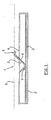
- FIG. 1 shows a device 1 for contacting which is particularly preferred Way for contacting electronic devices with parts of vehicles can be used.
- a housing 2 of an electronic device is shown, which receives a circuit board 3.
- On the circuit board 3 are (not represented) electrical, electronic and mechanical components present, the for example, an antenna amplifier circuit.
- this has a recess for a Tab 5 on.
- This tab 5 is part of the housing 2 and protrudes through the Recess 4 to the outside.
- the shape of the tab 5 may also be referred to as a lever become.
- the tab. 5 also from this material, and it is of particular advantage when using Production of the housing 2 and the tab 5 is made, that is, the Housing 2 and the tab form part. But also the subsequent attachment the tab 5 on the housing 2 is conceivable, as well as the attachment the electrically conductive tab 5 as a separate component during manufacture of the housing 2, so a partial encapsulation of the tab 5. In the case of a Plastic existing tab 5 it is still necessary to use this one electrically conductive layer 6 to provide. Since the tab 5 as a contact element it is between two adjacently arranged contact surfaces 7, 8th arranged.
- an electrically not conductive material for example, plastic
- the adjacent to the contact surface 7 arranged contact surface 8 is on a particular flat component 9, at for example, a vehicle window or any other Part of a vehicle can act arranged.
- signals from an antenna structure on or in the plane Component 9 are received, via the trained as a tab 5 contact element transferred to the components on the circuit board 3.
- Figure 2 shows the device 1 for contacting with a bracket 10, which is approximately S-shaped.
- a first end 11 is the bracket 10 in the housing 2 (or cover, support frame or other Component of the housing), which again has a recess 4, through which a half bow of the bracket 10 protrudes.
- a second end 12 of the bracket 10 is angled and provides on the one hand a stop in the rest position, on the other hand limits it the deflection path of the bracket 10.
- the bracket is located on the contact surface 7 of Circuit board 3 and the contact surface 8 on the sheet-like member 9 at. This will adjacent the electrical connection between these two arranged contact surfaces 7, 8 produced.
- the advantages of the bracket 10 are the same as the flap 5.
- bracket 10 is not S-shaped, but only designed as a simple semicircular arc is (although other geometric shapes are conceivable).
- bracket 10 S-shaped is formed and in addition to the contacting of the two contact surfaces 7, 8th each other even further contacting functions with interconnects, Components or the like on the circuit board 3 takes over.
Landscapes
- Coupling Device And Connection With Printed Circuit (AREA)
- Details Of Aerials (AREA)
Applications Claiming Priority (4)
| Application Number | Priority Date | Filing Date | Title |
|---|---|---|---|
| DE10336845 | 2003-08-11 | ||
| DE10336845 | 2003-08-11 | ||
| DE10357898 | 2003-12-11 | ||
| DE10357898A DE10357898A1 (de) | 2003-08-11 | 2003-12-11 | Hebelartige Kontaktelemente |
Publications (1)
| Publication Number | Publication Date |
|---|---|
| EP1507308A2 true EP1507308A2 (fr) | 2005-02-16 |
Family
ID=33566033
Family Applications (1)
| Application Number | Title | Priority Date | Filing Date |
|---|---|---|---|
| EP04018788A Pending EP1507308A2 (fr) | 2003-08-11 | 2004-08-07 | Eléments de contact du type à levier |
Country Status (2)
| Country | Link |
|---|---|
| US (1) | US7121902B2 (fr) |
| EP (1) | EP1507308A2 (fr) |
Families Citing this family (2)
| Publication number | Priority date | Publication date | Assignee | Title |
|---|---|---|---|---|
| DE102005034084A1 (de) * | 2005-07-21 | 2007-02-01 | Hirschmann Car Communication Gmbh | Elektronisches Gerät für ein Fahrzeug mit einer direkt kontaktierten Leiterplatte |
| CN202930669U (zh) * | 2012-04-10 | 2013-05-08 | 番禺得意精密电子工业有限公司 | 电连接器 |
Family Cites Families (15)
| Publication number | Priority date | Publication date | Assignee | Title |
|---|---|---|---|---|
| DE2010193A1 (de) | 1970-03-04 | 1971-09-30 | Intreprinderea de constructii din prefabricate de beton bucuresti, Bukarest | Fenster ohne Fensterrahmen und Verfahren zu dessen Herstellung |
| US4262986A (en) | 1979-09-12 | 1981-04-21 | Amp Incorporated | Electrical interconnect device |
| US4969842A (en) * | 1989-11-30 | 1990-11-13 | Amp Incorporated | Molded electrical connector having integral spring contact beams |
| US5015191A (en) | 1990-03-05 | 1991-05-14 | Amp Incorporated | Flat IC chip connector |
| GB9020002D0 (en) * | 1990-09-13 | 1990-10-24 | Amp Holland | Card reader |
| DE4118312C2 (de) | 1991-06-04 | 1995-03-09 | Amphenol Tuchel Elect | Kontaktsatz für eine Kontaktzonen aufweisende Karte |
| US5378160A (en) * | 1993-10-01 | 1995-01-03 | Bourns, Inc. | Compliant stacking connector for printed circuit boards |
| DE19605999C2 (de) * | 1996-02-17 | 1999-10-14 | Daimler Chrysler Ag | Kontaktierung einer flächigen Antennenleiterstruktur |
| DE19823202C2 (de) * | 1998-05-25 | 2003-05-28 | Hirschmann Electronics Gmbh | Fahrzeug-Antenneneinrichtung |
| DE19934302C2 (de) | 1999-07-21 | 2003-02-13 | Amphenol Tuchel Elect | Kontaktiereinrichtung und Kontaktelement |
| US6118410A (en) * | 1999-07-29 | 2000-09-12 | General Motors Corporation | Automobile roof antenna shelf |
| US6375474B1 (en) | 1999-08-09 | 2002-04-23 | Berg Technology, Inc. | Mezzanine style electrical connector |
| US6198444B1 (en) * | 1999-11-09 | 2001-03-06 | Motorola, Inc. | Double pole limit switch having an actuator as a pole |
| US6625881B2 (en) * | 2001-09-11 | 2003-09-30 | Xytrans, Inc. | Solderless method for transferring high frequency, radio frequency signals between printed circuit boards |
| DE10258101B3 (de) * | 2002-12-11 | 2004-04-08 | Hirschmann Electronics Gmbh & Co. Kg | Kontaktfeder für eine Antenneneinrichtung für ein Fahrzeug |
-
2004
- 2004-08-07 EP EP04018788A patent/EP1507308A2/fr active Pending
- 2004-08-11 US US10/916,763 patent/US7121902B2/en not_active Expired - Fee Related
Also Published As
| Publication number | Publication date |
|---|---|
| US20050037676A1 (en) | 2005-02-17 |
| US7121902B2 (en) | 2006-10-17 |
Similar Documents
| Publication | Publication Date | Title |
|---|---|---|
| DE19742458C1 (de) | Kunststoffgehäuse zur Aufnahme einer elektrischen Leiterplatte | |
| EP0904613B1 (fr) | Connecteur multibroches a structure conductrice comportant des composants electriques, et procede de fabrication associe | |
| EP1197402A2 (fr) | Volant de véhicule | |
| WO2012010152A2 (fr) | Ensemble électrique pour un véhicule automobile, approprié pour la connexion avec un connecteur | |
| EP2380241B1 (fr) | Connecteur de contact et connexion par connecteur de contact | |
| EP1608994B1 (fr) | Ensemble capteur d'un systeme d'aide au stationnement | |
| DE202004021354U1 (de) | Elastische Kontaktelemente | |
| DE102008035420A1 (de) | Modulare Schaltungsanordnung | |
| EP3330737B1 (fr) | Capteur radar pour un véhicule et procédé d'assemblage d'un capteur radar | |
| EP1507308A2 (fr) | Eléments de contact du type à levier | |
| DE102020005469A1 (de) | Verbindungsanordnung | |
| WO2015097144A1 (fr) | Module de coussin gonflable | |
| DE102016224657A1 (de) | Verfahren zum Verbinden eines Bauelementträgers mit einer Leiterplatte und Verbund aus einer Leiterplatte und einem Bauelementträger | |
| DE19606184A1 (de) | Baugruppe | |
| WO2008087091A1 (fr) | Composant de contact en plusieurs pièces | |
| DE102023107028B4 (de) | Lenkrad für ein Fahrzeug, Fahrzeug und elektronische Baugruppe | |
| DE102015111885A1 (de) | Sicherung für Stromverteiler | |
| EP1507310A1 (fr) | Connecteur élastique avec verrouillage | |
| DE102018113757A1 (de) | Abdeckung für Batteriegehäuse | |
| DE102012108859B4 (de) | Elektronikmodul | |
| EP1507309A1 (fr) | Connecteur avec verrouillage | |
| DE102023132202A1 (de) | Befestigung von Steuergeräten | |
| DE102021124086A1 (de) | Gehäuse, insbesondere Schlossgehäuse für einen Kraftfahrzeugtürverschluss | |
| DE202023003033U1 (de) | Lenkrad für ein Fahrzeug, Fahrzeug und elektronische Baugruppe | |
| DE102024000676A1 (de) | Bauteilanordnung mit zwei Bauteilen und Verfahren zu deren Montage |
Legal Events
| Date | Code | Title | Description |
|---|---|---|---|
| PUAI | Public reference made under article 153(3) epc to a published international application that has entered the european phase |
Free format text: ORIGINAL CODE: 0009012 |
|
| AK | Designated contracting states |
Kind code of ref document: A2 Designated state(s): AT BE BG CH CY CZ DE DK EE ES FI FR GB GR HU IE IT LI LU MC NL PL PT RO SE SI SK TR |
|
| AX | Request for extension of the european patent |
Extension state: AL HR LT LV MK |
|
| STAA | Information on the status of an ep patent application or granted ep patent |
Free format text: STATUS: THE APPLICATION IS DEEMED TO BE WITHDRAWN |