EP1507351A2 - Système à multiplexage en longueurs d'ondes bidirectioneel - Google Patents
Système à multiplexage en longueurs d'ondes bidirectioneel Download PDFInfo
- Publication number
- EP1507351A2 EP1507351A2 EP04016032A EP04016032A EP1507351A2 EP 1507351 A2 EP1507351 A2 EP 1507351A2 EP 04016032 A EP04016032 A EP 04016032A EP 04016032 A EP04016032 A EP 04016032A EP 1507351 A2 EP1507351 A2 EP 1507351A2
- Authority
- EP
- European Patent Office
- Prior art keywords
- upstream
- downstream
- layer deposited
- bragg reflector
- channels
- Prior art date
- Legal status (The legal status is an assumption and is not a legal conclusion. Google has not performed a legal analysis and makes no representation as to the accuracy of the status listed.)
- Withdrawn
Links
Images



Classifications
-
- H—ELECTRICITY
- H04—ELECTRIC COMMUNICATION TECHNIQUE
- H04Q—SELECTING
- H04Q11/00—Selecting arrangements for multiplex systems
- H04Q11/0001—Selecting arrangements for multiplex systems using optical switching
- H04Q11/0062—Network aspects
- H04Q11/0067—Provisions for optical access or distribution networks, e.g. Gigabit Ethernet Passive Optical Network (GE-PON), ATM-based Passive Optical Network (A-PON), PON-Ring
-
- H—ELECTRICITY
- H04—ELECTRIC COMMUNICATION TECHNIQUE
- H04B—TRANSMISSION
- H04B10/00—Transmission systems employing electromagnetic waves other than radio-waves, e.g. infrared, visible or ultraviolet light, or employing corpuscular radiation, e.g. quantum communication
- H04B10/25—Arrangements specific to fibre transmission
- H04B10/2589—Bidirectional transmission
-
- H—ELECTRICITY
- H04—ELECTRIC COMMUNICATION TECHNIQUE
- H04B—TRANSMISSION
- H04B10/00—Transmission systems employing electromagnetic waves other than radio-waves, e.g. infrared, visible or ultraviolet light, or employing corpuscular radiation, e.g. quantum communication
- H04B10/50—Transmitters
- H04B10/501—Structural aspects
- H04B10/503—Laser transmitters
- H04B10/505—Laser transmitters using external modulation
-
- H—ELECTRICITY
- H04—ELECTRIC COMMUNICATION TECHNIQUE
- H04J—MULTIPLEX COMMUNICATION
- H04J14/00—Optical multiplex systems
- H04J14/02—Wavelength-division multiplex systems
- H04J14/0201—Add-and-drop multiplexing
- H04J14/0202—Arrangements therefor
-
- H—ELECTRICITY
- H04—ELECTRIC COMMUNICATION TECHNIQUE
- H04J—MULTIPLEX COMMUNICATION
- H04J14/00—Optical multiplex systems
- H04J14/02—Wavelength-division multiplex systems
- H04J14/0226—Fixed carrier allocation, e.g. according to service
-
- H—ELECTRICITY
- H04—ELECTRIC COMMUNICATION TECHNIQUE
- H04J—MULTIPLEX COMMUNICATION
- H04J14/00—Optical multiplex systems
- H04J14/02—Wavelength-division multiplex systems
- H04J14/0227—Operation, administration, maintenance or provisioning [OAMP] of WDM networks, e.g. media access, routing or wavelength allocation
- H04J14/0241—Wavelength allocation for communications one-to-one, e.g. unicasting wavelengths
- H04J14/0242—Wavelength allocation for communications one-to-one, e.g. unicasting wavelengths in WDM-PON
- H04J14/0245—Wavelength allocation for communications one-to-one, e.g. unicasting wavelengths in WDM-PON for downstream transmission, e.g. optical line terminal [OLT] to ONU
- H04J14/0246—Wavelength allocation for communications one-to-one, e.g. unicasting wavelengths in WDM-PON for downstream transmission, e.g. optical line terminal [OLT] to ONU using one wavelength per ONU
-
- H—ELECTRICITY
- H04—ELECTRIC COMMUNICATION TECHNIQUE
- H04J—MULTIPLEX COMMUNICATION
- H04J14/00—Optical multiplex systems
- H04J14/02—Wavelength-division multiplex systems
- H04J14/0227—Operation, administration, maintenance or provisioning [OAMP] of WDM networks, e.g. media access, routing or wavelength allocation
- H04J14/0241—Wavelength allocation for communications one-to-one, e.g. unicasting wavelengths
- H04J14/0242—Wavelength allocation for communications one-to-one, e.g. unicasting wavelengths in WDM-PON
- H04J14/0249—Wavelength allocation for communications one-to-one, e.g. unicasting wavelengths in WDM-PON for upstream transmission, e.g. ONU-to-OLT or ONU-to-ONU
- H04J14/025—Wavelength allocation for communications one-to-one, e.g. unicasting wavelengths in WDM-PON for upstream transmission, e.g. ONU-to-OLT or ONU-to-ONU using one wavelength per ONU, e.g. for transmissions from-ONU-to-OLT or from-ONU-to-ONU
-
- H—ELECTRICITY
- H04—ELECTRIC COMMUNICATION TECHNIQUE
- H04J—MULTIPLEX COMMUNICATION
- H04J14/00—Optical multiplex systems
- H04J14/02—Wavelength-division multiplex systems
- H04J14/0278—WDM optical network architectures
- H04J14/0282—WDM tree architectures
-
- H—ELECTRICITY
- H04—ELECTRIC COMMUNICATION TECHNIQUE
- H04J—MULTIPLEX COMMUNICATION
- H04J14/00—Optical multiplex systems
- H04J14/02—Wavelength-division multiplex systems
- H04J14/03—WDM arrangements
- H04J14/0307—Multiplexers; Demultiplexers
-
- G—PHYSICS
- G02—OPTICS
- G02B—OPTICAL ELEMENTS, SYSTEMS OR APPARATUS
- G02B6/00—Light guides; Structural details of arrangements comprising light guides and other optical elements, e.g. couplings
- G02B6/02—Optical fibres with cladding with or without a coating
- G02B6/02057—Optical fibres with cladding with or without a coating comprising gratings
- G02B6/02076—Refractive index modulation gratings, e.g. Bragg gratings
Definitions
- the present invention relates to an optical communication system, and more particularly to a Wavelength Division Multiplexing (WDM) passive optical communication system.
- WDM Wavelength Division Multiplexing
- a WDM PON(Passive Optical Communication) mainly includes a center office, a plurality of subscribers, and a local office (or a remote node).
- the central office is configured to multiplex a plurality of downstream channels of different wavelengths into a downstream optical signal and outputs the multiplexed optical signal.
- the local office connects the central office with the subscribers.
- the local office multiplexes the upstream channels received from the subscribers into an upstream optical signal and outputs the upstream optical signal to the central office.
- the local office demultiplexes the downstream optical signal received from the central office into downstream channels of different wavelengths and outputs the downstream channels to corresponding subscribers.
- the central office demultiplexes upstream optical signal received from the local office into a plurality of upstream channels and detects the upstream signals. It further generates a plurality of downstream channels of different preset wavelengths.
- the central office also multiplexes the downstream channels into a downstream optical signal and outputs the downstream optical signal to the local office.
- a light source and a photodiode are used as an optical signal generator and an optical detector means at the subscriber end, respectively.
- An upstream channel to the local office is generated and a downstream channel received from the local office is detected by each subscriber, so that subscribers can perform a bi-directional communication with the central office.
- a coherent light source such as a DFB (Distributed Feedback) laser array, an MFL (Multi-Frequency Laser), a FP-LD(Fabry-Perot Laser Diode), an R-SOA (Reflective Semiconductor Optical Amplifier) or the like, or an incoherent light source such as an LED (Light Emitting Diode) is used as a light source for generating the upstream or downstream channel.
- a superluminescent diode, other than the LED, may also be used as the incoherent light source.
- the Fabry-Perot laser may be used in conjunction with an incoherent light source.
- an incoherent light source For example, after a light beam of a wide wavelength band outputted from a EDFA(Erbuim Doped Fiber Amplifier) or LED or the like is divided into a plurality of incoherent beams of different wavelengths, each of the incoherent beams is inputted to a corresponding FP-LD to induce a wavelength-locked state (also referred to as a mode-locked state or an injection-locked state), which allows the FP-LD to output a channel of the same wavelength as the inputted incoherent beam.
- a wavelength-locked state also referred to as a mode-locked state or an injection-locked state
- the optical transmitter including the FP-LD has a drawback in that the wavelength or gain of a channel outputted from it varies greatly depending on the temperature since lasing characteristics of the Fabry-Perot laser are highly dependent on temperature. As temperature varies, variations in the wavelength or gain of a channel outputted from the light source can cause the conventional WDM system to malfunction.
- the present invention has been made in view of the above problem and provides additional advantages. It is the object of the present invention to provide a bi-directional WDM passive communication system whose gain and wavelength are not affected by temperature changes.
- a bi-directional WDM passive communication system includes: a central office including downstream Bragg reflector lasers for generating a plurality of downstream channels of different wavelengths, each downstream channel being wavelength-locked to a corresponding incoherent light beam.
- the central office multiplexes the downstream channels into a downstream optical signal, outputs the multiplexed downstream optical signal, demultiplexes an upstream optical signal into a plurality of upstream channels having different wavelengths, and detects the upstream channels.
- the WDM passive communication system further includes a local office for demultiplexing a downstream optical signal received from the central office into a plurality of downstream channels, outputting the demultiplexed downstream channels, multiplexing a plurality of upstream channels of different wavelengths inputted to the local office into an upstream optical signal, outputting the multiplexed upstream optical signal to the central office, demultiplexing a broadband light beam into a plurality of incoherent light beams of different wavelengths, and outputting the demultiplexed incoherent light beams; and a plurality of subscribers, each subscriber receiving a corresponding downstream channel and a corresponding incoherent light beam, each subscriber including an upstream Bragg reflector laser for generating an upstream channel wavelength-locked to the received incoherent light beam, each subscriber outputting the upstream channel to the local office.
- a local office for demultiplexing a downstream optical signal received from the central office into a plurality of downstream channels, outputting the demultiplexed downstream channels, multiplex
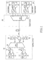
- Fig. 1 shows the configuration of a WDM (Wavelength Division Multiplexing) passive communication system including a Bragg reflector laser according to the present invention.
- the WDM passive optical communication system according to the present invention includes a central office 130, a plurality of subscribers 301 and 302, and a local office 200.
- the central office 130 includes n (1st to nth) downstream Bragg reflector lasers 111 and 112. Note that the number of these Bragg reflector lasers is n, but they are denoted by only two references to avoid redundancy, and the same is true for other plural elements in the drawings.
- the plurality of n subscribers 301 and 302 include a plurality of upstream Bragg reflector lasers 331 and 332 for generating upstream channels, respectively.
- the local office 200 serves to connect the central office 130 to the subscribers 301 and 302.
- the central office 130 includes n downstream Bragg reflector lasers 111 and 112, a downstream broadband light source 140, a multiplexer/demultiplexer 160, a circulator 170, an upstream broadband light source 150, n optical detectors 121 and 122, and n wavelength-selective couplers 131 and 132, and WDM filters 180, and 190.
- the circulator 170 receives an upstream optical signals through its fourthly port connected to the local office 200, and outputs the received upstream optical signal through its primary port.
- the upstream optical signal is reflected back to a primary port by the WDM filter 190, and outputs it through a secondary port connected to the multiplexer/demultiplexer 160.
- the circulator 170 receives downstream optical signals through the secondary port and outputs it through a tertiary port.
- the downstream optical signal is reflected back to the tertiary port by the WDM filter 180, and outputs it through the fourthly port connected to the remote node 200.
- the multiplexer/demultiplexer 160 demultiplexes the broadband beam from the light source 140 into a plurality of incoherent beams ( ⁇ 1 to ⁇ n ) of different wavelengths (i.e., 1st to nth wavelengths), and demultiplexes the upstream optical signal into a plurality of upstream channels ( ⁇ n+1 to ⁇ 2n ) of different wavelengths.
- the multiplexer/demultiplexer 160 outputs the n (1st to nth) upstream channels and n (1st to nth) incoherent beams to the n (1st to nth) wavelength-selective couplers 131 and 132 connected respectively to n (1st to nth) secondary ports of the multiplexer/demultiplexer 160, respectively.
- an incoherent beam of a wavelength ⁇ 1 is referred to as a 1 st incoherent beam
- an incoherent beam of a wavelength ⁇ n is referred to as an nth incoherent beam.
- an upstream channel of a wavelength ⁇ n+1 is referred to as a 1st upstream channel
- an upstream channel of a wavelength ⁇ 2n is referred to as an nth upstream channel.
- Each of the 1st to nth downstream Bragg reflector lasers 111 and 112 generates a downstream channel whose wavelength is locked to the wavelength of a corresponding one of the 1st to nth incoherent beams.
- the 1 st downstream Bragg reflector laser 111 generates a downstream channel whose wavelength is locked to the wavelength ⁇ 1 of the 1st incoherent beam
- the nth downstream Bragg reflector laser 112 generates a downstream channel whose wavelength is locked to the wavelength ⁇ n of the nth incoherent beam.
- the 1 st to nth wavelength-selective couplers 131 and 132 are connected to the 1 st to nth secondary ports of the multiplexer/demultiplexer 160, the 1st to nth downstream Bragg reflector lasers 111 and 112, and the 1st to nth optical detectors 121 and 122, respectively.
- the 1st wavelength-selective coupler 131 is connected to the 1st secondary port of the multiplexer/demultiplexer 160, the 1st downstream Bragg reflector laser 111, and the 1st optical detector 121.
- the 1st wavelength-selective coupler 131 receives the 1st incoherent beam ( ⁇ 1 ) and the 1st upstream channel ( ⁇ n+1 ) through a primary port thereof connected to the 1st secondary port of the multiplexer/demultiplexer 160, and outputs the 1st incoherent beam ( ⁇ 1 ) through a tertiary port thereof connected to the 1st downstream Bragg reflector laser 111 and a secondary port thereof connected to the 1 st optical detector 121, respectively.
- the 1st wavelength-selective coupler 131 receives a 1st downstream channel ( ⁇ 1 ) generated by the 1st downstream Bragg reflector laser 111 through the tertiary port, and outputs it to the multiplexer/demultiplexer 160 through the primary port.
- the WDM filter 190 reflects the upstream optical signals and also transmits the received broadband beam, so that the upstream optical signals and the broadband beam are inputted to the circulator 170 through the primary port thereof.
- the circulator 170 outputs the upstream optical signals and the broadband beam inputted through the primary port to the multiplexer/demultiplexer 160 through the secondary port.
- the WDM filter 180 is disposed between the upstream broadband light source 150 and the tertiary port of the circulator 170, whereby the downstream optical signal outputted from the secondary port of the circulator 170 is reflected backward to the tertiary port of the circulator 170, and the broadband beam received from the upstream broadband light source 150 is outputted to the tertiary port of the circulator 170.
- the WDM filter 180 reflects the downstream optical signal and also transmits the received broadband beam so that the downstream optical signal and the broadband beam are inputted to the circulator 170 through the tertiary port thereof.
- the circulator 170 outputs the downstream optical signal and the broadband beam inputted through the tertiary port to the multiplexer/demultiplexer 220 through the fourthly port.
- the local office 200 includes a multiplexer/demultiplexer 220.
- the local office 200 is located between the central office 130 and the n subscribers 301 and 302 to connect the central office 130 with the n subscribers 301 and 302.
- the local office 220 multiplexes n upstream channels ( ⁇ n+1 ⁇ ⁇ 2n ) generated respectively from the n subscribers 301 and 302 into an upstream optical signal, and outputs the upstream optical signal to the central office 130.
- the local office 220 demultiplexes a downstream optical signal received from the central office 130 into n (1st to nth) downstream channels ( ⁇ 1 ⁇ ⁇ n ), and outputs the n (1st to nth) downstream channels to the n (1st to nth) subscribers 301 and 302, respectively.
- the upstream broadband light source 150 inputs a broadband beam to allow the subscribers 301 to generate wavelength-locked upstream channels ( ⁇ n+1 ⁇ ⁇ 2n ).
- the multiplexer/demultiplexer 220 multiplexes the n upstream channels ( ⁇ n+1 ⁇ ⁇ 2n ) into an upstream optical signal and outputs the upstream optical signal and demultiplexes the downstream optical signal into n downstream channels ( ⁇ 1 ⁇ ⁇ n ) of different wavelengths.
- the n subscribers 301 and 302 are connected respectively to the n secondary ports of the multiplexer/demultiplexer 220in the local office 200.
- the n subscribers 301 and 302 include n upstream Bragg reflector lasers 331 and 332, n optical detectors 321 and 322, and n wavelength-selective couplers 311 and 312, respectively.
- the 1st subscriber 301 detects the 1st downstream channel, and outputs the 1 st upstream channel of a wavelength ⁇ n+1 .
- the nth subscriber 302 detects the nth downstream channel, and outputs the nth upstream channel of a wavelength ⁇ 2n .
- the 1st upstream channel is outputted from the 1st subscriber 301 and the nth upstream channel is outputted from the nth subscriber 302.
- the 1st subscriber 301 includes an optical detector 321 for detecting the 1st downstream channel, an upstream Bragg reflector laser 331 for generating the 1st upstream channel, and a wavelength-selective coupler 311 for outputting the 1st upstream channel to the local office 200 and outputting the 1st downstream channel to the 1st optical detector 321.
- Fig. 6 is a graph showing changes in the wavelength and the gain of a conventional FP-LD as temperature varies
- Fig. 7 is a graph showing changes in the wavelength and the gain of a Bragg reflector laser according to the present invention as temperature varies (i.e., as temperature increases to T+ or decreases to T- from appropriate temperature T0).
- x and y-axes represent the wavelength and intensity of light outputted from the light source, respectively. That is, the two graphs show the wavelength with respect to the intensity at an appropriate temperature T0, a higher temperature T+ and a lower temperature T-. From the comparison of the two graphs, it can be seen that the center wavelength shift as temperature varies and the corresponding gain (or intensity) difference in Fig.
- the WDM passive optical communication system since the present invention uses the Bragg reflector laser as a light source for generating a wavelength-locked channel whose wavelength is locked to the wavelength of an incoherent beam, the WDM passive optical communication system according to the present invention has an advantage in that the dependency of the center wavelength and the gain of each channel on temperature is reduced.
- Fig. 2 is a perspective view showing the configuration of the Bragg reflector laser shown in Fig. 1.
- the Bragg reflector laser includes an n-InP substrate 401, an InGaAsP passive waveguide layer 402, an InP spacer 403, a Bragg grating 404, an active layer 405, a current blocking layer 406, a p-InP clad layer 407, a p-InGaAsP layer 408 for reducing ohmic contact resistance, an oxide layer 409, an upper electrode 410, and a lower electrode 411.
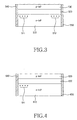
- Fig. 3 is a side sectional view showing the configuration of a Bragg reflector laser shown in Fig. 2, in which a pair of Bragg gratings 511 and 512 are formed at opposite ends of the laser.
- the Bragg reflector laser includes an n-InP substrate 510, a pair of Bragg gratings 511 and 512 formed on the substrate 510 at both sides thereof, an active layer 520 deposited on the n-InP substrate 510, and a p-InP clad layer 530 deposited on the active layer 520.
- An anti-reflective layer 540 is deposited at one end of the Bragg grating laser and a highly-reflective layer 550 is deposited at the other end thereof
- An incoherent beam of a predetermined wavelength is inputted to the Bragg reflector laser through the anti-reflective layer 540. After the inputted beam resonates between the Bragg gratings 511 and 512 a number of times, it is outputted as a wavelength-locked channel having a predetermined intensity from the Bragg reflector laser through the anti-reflective layer 540.
- Fig. 4 is a side sectional view showing the configuration of a Bragg reflector laser shown in Fig. 2 according to another embodiment of the present invention, As shown, a Bragg grating 611 is formed at one side of the laser, and highly-reflective layer 650 is formed in the laser at the other side thereof
- the Bragg reflector laser further includes an n-InP substrate 610, a Bragg grating 611 formed on the substrate 610, an active layer 620 deposited on the n-InP substrate 610, and a p-InP clad layer 630 deposited on the active layer 620.
- An anti-reflective layer 640 is deposited on one end of the Bragg grating laser, and a highly-reflective layer 650 is deposited on the other end thereof.
- the Bragg grating 611 is formed on the n-InP substrate 610 near the anti-reflective layer 640.
- An incoherent beam having a predetermined wavelength is inputted to the Bragg reflector laser through the anti-reflective layer 640. After the inputted beam resonates between the Bragg grating 611 and the highly-reflective layer 650 a number of times, it is outputted as a wavelength-locked channel having a predetermined intensity from the Bragg reflector laser through the anti-reflective layer 640.
- Fig. 5 is a side sectional view showing the configuration of a Bragg reflector laser according to still another embodiment that can be applied to the system shown in Fig. 1.
- the Bragg reflector laser includes an n-InP substrate 710, a Bragg grating 711 formed on the substrate 710, an active layer 720 deposited on the n-InP substrate 710, and a p-InP clad layer 730 deposited on the active layer 720.
- An anti-reflective layer 740 is deposited on one end of the Bragg grating laser, and a highly-reflective layer 750 is deposited on the other end thereof.
- the Bragg grating 711 is formed on the n-InP substrate 710 near the highly-reflective layer 730.
- An incoherent beam of a predetermined wavelength is inputted to the Bragg reflector laser through the anti-reflective layer 740. After the inputted beam is reflected by the Bragg grating 711, it is outputted as a wavelength-locked channel having a predetermined intensity from the Bragg reflector laser through the anti-reflective layer 740.
- a bi-directional WDM passive optical communication system since a Bragg reflector laser as a light source is used for outputting upstream and downstream channels, a bi-directional WDM passive optical communication system according to the present invention has an advantage in that it prevents changes in the wavelengths and the gains of the outputted channels due to changes in the peripheral temperature. As the wavelengths and the gains of the outputted channels due to the peripheral temperature changes can be prevented, the present invention also has an advantage in that it is capable of preventing a malfunction of the bi-directional WDM optical communication system due to signal disturbance.
Landscapes
- Engineering & Computer Science (AREA)
- Computer Networks & Wireless Communication (AREA)
- Signal Processing (AREA)
- Physics & Mathematics (AREA)
- Electromagnetism (AREA)
- Optics & Photonics (AREA)
- Optical Communication System (AREA)
Applications Claiming Priority (2)
| Application Number | Priority Date | Filing Date | Title |
|---|---|---|---|
| KR10-2003-0055882A KR100539927B1 (ko) | 2003-08-12 | 2003-08-12 | 양방향 파장 분할 다중 시스템 |
| KR2003055882 | 2003-08-12 |
Publications (2)
| Publication Number | Publication Date |
|---|---|
| EP1507351A2 true EP1507351A2 (fr) | 2005-02-16 |
| EP1507351A3 EP1507351A3 (fr) | 2006-11-29 |
Family
ID=33563041
Family Applications (1)
| Application Number | Title | Priority Date | Filing Date |
|---|---|---|---|
| EP04016032A Withdrawn EP1507351A3 (fr) | 2003-08-12 | 2004-07-07 | Système à multiplexage en longueurs d'ondes bidirectioneel |
Country Status (4)
| Country | Link |
|---|---|
| US (1) | US20050036787A1 (fr) |
| EP (1) | EP1507351A3 (fr) |
| JP (1) | JP4088280B2 (fr) |
| KR (1) | KR100539927B1 (fr) |
Cited By (1)
| Publication number | Priority date | Publication date | Assignee | Title |
|---|---|---|---|---|
| WO2007014055A1 (fr) * | 2005-07-22 | 2007-02-01 | Novera Optics, Inc. | Reseaux optiques passifs a multiplexage en longueur d'onde pour le transport de formats d'acces differents |
Families Citing this family (14)
| Publication number | Priority date | Publication date | Assignee | Title |
|---|---|---|---|---|
| KR100606028B1 (ko) * | 2004-07-07 | 2006-07-31 | 삼성전자주식회사 | 파장분할 다중방식 광통신용 광원 및 광통신 시스템 |
| US7548695B2 (en) * | 2004-10-19 | 2009-06-16 | Nextg Networks, Inc. | Wireless signal distribution system and method |
| KR100608946B1 (ko) * | 2004-10-20 | 2006-08-03 | 광주과학기술원 | 자체잠김된 페브리-페롯 레이저 다이오드를 이용한 파장분할다중 방식의 수동형 광통신망과, 이에 사용되는 지역 기지국 및 그 제어 방법 |
| KR100689503B1 (ko) * | 2004-12-30 | 2007-03-02 | 삼성전자주식회사 | 파장 분할 다중 방식 수동형 광 가입자망 |
| KR100711201B1 (ko) * | 2005-08-09 | 2007-04-24 | 한국과학기술원 | 광대역 비간섭성 광원의 위치 조정을 이용한 장거리 전송파장분할 다중방식 수동형 광 가입자망 |
| KR100757074B1 (ko) * | 2006-04-06 | 2007-09-10 | 한국과학기술연구원 | 잉여 라만 펌핑광을 재활용하여 펌핑된 가입자용 ase광원을 사용하는 라만 증폭 기반의 양방향 파장분할다중수동광네트워크 |
| KR100786040B1 (ko) * | 2006-05-19 | 2007-12-17 | 한국과학기술원 | 높은 스펙트럼 효율을 구비한 전송 포맷을 이용하여 고속광신호 전송이 가능한 파장 분할 다중방식 수동형 광가입자망 |
| KR100889861B1 (ko) * | 2007-05-09 | 2009-03-24 | 광주과학기술원 | 자체 잠김을 이용한 파장분할다중 방식의 수동형 광통신시스템, 이에 사용되는 중앙 기지국 및 데이터 전송 방법 |
| WO2010074782A2 (fr) * | 2008-10-01 | 2010-07-01 | Ziva Corporation | Communications optiques dans des réseaux réciproques amplifiés |
| WO2010042319A2 (fr) | 2008-10-10 | 2010-04-15 | Ziva Corporation | Techniques et systèmes destinés à des communications sans fil |
| US8743976B2 (en) | 2009-09-03 | 2014-06-03 | Ziva Corporation | Techniques and systems for communications based on time reversal pre-coding |
| KR20120070260A (ko) * | 2010-12-21 | 2012-06-29 | 한국전자통신연구원 | 파장 분할 다중화 기반 수동형 광가입자망용 씨앗 광 모듈 및 그 구동 방법 |
| US9287987B2 (en) * | 2011-12-01 | 2016-03-15 | Futurewei Technologies, Inc. | Self-seeded colorless burst-mode transmitter using reflective semiconductor optical amplifier and injection locked Fabry-Perot laser |
| US8893495B2 (en) | 2012-07-16 | 2014-11-25 | Cummins Intellectual Property, Inc. | Reversible waste heat recovery system and method |
Family Cites Families (9)
| Publication number | Priority date | Publication date | Assignee | Title |
|---|---|---|---|---|
| US5392308A (en) * | 1993-01-07 | 1995-02-21 | Sdl, Inc. | Semiconductor laser with integral spatial mode filter |
| FR2709189B1 (fr) * | 1993-08-20 | 1995-09-15 | Alcatel Nv | Amplificateur optique à semiconducteur, présentant une non-linéarité réduite. |
| US6501777B1 (en) * | 1999-01-29 | 2002-12-31 | Nec Corporation | Distributed feedback semiconductor laser emitting device having asymmetrical diffraction gratings |
| KR100325687B1 (ko) * | 1999-12-21 | 2002-02-25 | 윤덕용 | 주입된 비간섭성 광에 파장 잠김된 페브리-페롯 레이저다이오드를 이용한 파장분할 다중방식 광통신용 광원 |
| JP2003023209A (ja) * | 2001-07-06 | 2003-01-24 | Furukawa Electric Co Ltd:The | 半導体素子の製造方法および半導体素子 |
| JP2003133638A (ja) * | 2001-08-14 | 2003-05-09 | Furukawa Electric Co Ltd:The | 分布帰還型半導体レーザ素子及びレーザモジュール |
| KR100496710B1 (ko) * | 2002-01-21 | 2005-06-28 | 노베라옵틱스코리아 주식회사 | 주입된 비간섭성 광에 파장 잠김된 광원을 이용한 양방향파장분할다중방식 수동형 광 네트워크 |
| KR100454887B1 (ko) * | 2002-01-30 | 2004-11-06 | 한국과학기술원 | 파장분할 다중방식 수동 광 네트워크 장치 |
| KR100515259B1 (ko) * | 2002-05-03 | 2005-09-15 | 한국과학기술원 | 파장 가변 광원 구현 방법 및 장치와 이 광원을 이용한 파장분할 다중방식 광전송 장치 |
-
2003
- 2003-08-12 KR KR10-2003-0055882A patent/KR100539927B1/ko not_active Expired - Fee Related
-
2004
- 2004-04-28 US US10/834,323 patent/US20050036787A1/en not_active Abandoned
- 2004-07-07 EP EP04016032A patent/EP1507351A3/fr not_active Withdrawn
- 2004-08-12 JP JP2004234983A patent/JP4088280B2/ja not_active Expired - Fee Related
Non-Patent Citations (1)
| Title |
|---|
| None * |
Cited By (2)
| Publication number | Priority date | Publication date | Assignee | Title |
|---|---|---|---|---|
| WO2007014055A1 (fr) * | 2005-07-22 | 2007-02-01 | Novera Optics, Inc. | Reseaux optiques passifs a multiplexage en longueur d'onde pour le transport de formats d'acces differents |
| US7627246B2 (en) | 2005-07-22 | 2009-12-01 | Novera Optics, Inc. | Wavelength division multiplexing passive optical networks to transport access platforms |
Also Published As
| Publication number | Publication date |
|---|---|
| EP1507351A3 (fr) | 2006-11-29 |
| JP2005065287A (ja) | 2005-03-10 |
| KR20050017064A (ko) | 2005-02-21 |
| KR100539927B1 (ko) | 2005-12-28 |
| US20050036787A1 (en) | 2005-02-17 |
| JP4088280B2 (ja) | 2008-05-21 |
Similar Documents
| Publication | Publication Date | Title |
|---|---|---|
| KR100547716B1 (ko) | 파장 분할 다중 방식의 수동형 광가입자망 시스템 | |
| EP1507351A2 (fr) | Système à multiplexage en longueurs d'ondes bidirectioneel | |
| TWI452852B (zh) | Optical transceivers and wavelength division multiplexing passive optical network system | |
| US7224519B2 (en) | Low noise multi-wavelength light source and wavelength division multiplexing system using same | |
| EP2732514B1 (fr) | Ensemble multiplexeur à réseau laser à réflecteur extérieur pour fournir une longueur d'onde choisie ou des longueurs d'onde multiplexées | |
| CN105379159B (zh) | 具有多个序列式区段的可调谐激光器及其应用系统与方法 | |
| US20050041971A1 (en) | Multi-wavelength optical transmitter and bi-directional wavelength division multiplexing system using the same | |
| JP5491263B2 (ja) | 両方向光通信ネットワークで分布ラマン増幅および遠隔ポンピングを使用する方法および装置 | |
| CN101689956A (zh) | 被周期性滤波的宽带光源 | |
| EP2732566B1 (fr) | Dispositif laser sélectionnable en longueur d'onde et appareil et système comprenant ce dispositif | |
| WO2014055730A1 (fr) | Système de multiplexage par répartition en longueur d'onde à réseau laser filtré à modulation externe | |
| US8818208B2 (en) | Laser mux assembly for providing a selected wavelength | |
| US7398021B2 (en) | Optical transmitter and passive optical network using the same | |
| EP2320257A2 (fr) | Résonateur à base de points quantiques ayant un revêtement anti-réfléchissant utilisé dans des systèmes de communication optique à multiplexage par division de longueur d'onde | |
| US20170040774A1 (en) | Extended cavity fabry-perot laser assembly capable of high speed optical modulation with narrow mode spacing and wdm optical system including same | |
| JP4025761B2 (ja) | 多波長レージング光源及び反射型光増幅手段を用いた波長分割多重方式受動型光加入者網 | |
| KR101038219B1 (ko) | 파장 분할 다중 방식 수동형 광 네트워크용 광대역 광원 | |
| JPH06130438A (ja) | 回折格子を有する光検出装置及び光通信ネットワーク | |
| KR101095371B1 (ko) | 페브리-페롯 필터를 이용한 자체 잠김 방식의 수동형 광통신 시스템 |
Legal Events
| Date | Code | Title | Description |
|---|---|---|---|
| PUAI | Public reference made under article 153(3) epc to a published international application that has entered the european phase |
Free format text: ORIGINAL CODE: 0009012 |
|
| 17P | Request for examination filed |
Effective date: 20040707 |
|
| AK | Designated contracting states |
Kind code of ref document: A2 Designated state(s): AT BE BG CH CY CZ DE DK EE ES FI FR GB GR HU IE IT LI LU MC NL PL PT RO SE SI SK TR |
|
| AX | Request for extension of the european patent |
Extension state: AL HR LT LV MK |
|
| PUAL | Search report despatched |
Free format text: ORIGINAL CODE: 0009013 |
|
| AK | Designated contracting states |
Kind code of ref document: A3 Designated state(s): AT BE BG CH CY CZ DE DK EE ES FI FR GB GR HU IE IT LI LU MC NL PL PT RO SE SI SK TR |
|
| AX | Request for extension of the european patent |
Extension state: AL HR LT LV MK |
|
| RIC1 | Information provided on ipc code assigned before grant |
Ipc: H01S 5/125 20060101ALI20061026BHEP Ipc: H01S 5/50 20060101ALI20061026BHEP Ipc: H01S 5/00 20060101ALI20061026BHEP Ipc: H04J 14/02 20060101AFI20040824BHEP |
|
| 17Q | First examination report despatched |
Effective date: 20070123 |
|
| AKX | Designation fees paid |
Designated state(s): DE FR GB |
|
| STAA | Information on the status of an ep patent application or granted ep patent |
Free format text: STATUS: THE APPLICATION IS DEEMED TO BE WITHDRAWN |
|
| 18D | Application deemed to be withdrawn |
Effective date: 20101112 |