EP1507938B1 - Verfahren zur herstellung eines stahlträgers und stahlträger - Google Patents
Verfahren zur herstellung eines stahlträgers und stahlträger Download PDFInfo
- Publication number
- EP1507938B1 EP1507938B1 EP03725251A EP03725251A EP1507938B1 EP 1507938 B1 EP1507938 B1 EP 1507938B1 EP 03725251 A EP03725251 A EP 03725251A EP 03725251 A EP03725251 A EP 03725251A EP 1507938 B1 EP1507938 B1 EP 1507938B1
- Authority
- EP
- European Patent Office
- Prior art keywords
- base plate
- web
- parts
- supports
- steel beam
- Prior art date
- Legal status (The legal status is an assumption and is not a legal conclusion. Google has not performed a legal analysis and makes no representation as to the accuracy of the status listed.)
- Expired - Lifetime
Links
- 238000000034 method Methods 0.000 title claims abstract description 18
- 229910000831 Steel Inorganic materials 0.000 title claims abstract description 17
- 239000010959 steel Substances 0.000 title claims abstract description 17
- 238000004519 manufacturing process Methods 0.000 title claims abstract description 12
- 239000002131 composite material Substances 0.000 claims abstract description 7
- 239000000463 material Substances 0.000 claims abstract description 6
- 238000003466 welding Methods 0.000 description 3
- 238000005520 cutting process Methods 0.000 description 1
- 238000011065 in-situ storage Methods 0.000 description 1
Images

Classifications
-
- E—FIXED CONSTRUCTIONS
- E04—BUILDING
- E04C—STRUCTURAL ELEMENTS; BUILDING MATERIALS
- E04C3/00—Structural elongated elements designed for load-supporting
- E04C3/02—Joists; Girders, trusses, or trusslike structures, e.g. prefabricated; Lintels; Transoms; Braces
- E04C3/04—Joists; Girders, trusses, or trusslike structures, e.g. prefabricated; Lintels; Transoms; Braces of metal
- E04C3/06—Joists; Girders, trusses, or trusslike structures, e.g. prefabricated; Lintels; Transoms; Braces of metal with substantially solid, i.e. unapertured, web
- E04C3/065—Joists; Girders, trusses, or trusslike structures, e.g. prefabricated; Lintels; Transoms; Braces of metal with substantially solid, i.e. unapertured, web with special adaptations for the passage of cables or conduits through the web
-
- E—FIXED CONSTRUCTIONS
- E04—BUILDING
- E04B—GENERAL BUILDING CONSTRUCTIONS; WALLS, e.g. PARTITIONS; ROOFS; FLOORS; CEILINGS; INSULATION OR OTHER PROTECTION OF BUILDINGS
- E04B5/00—Floors; Floor construction with regard to insulation; Connections specially adapted therefor
- E04B5/16—Load-carrying floor structures wholly or partly cast or similarly formed in situ
- E04B5/17—Floor structures partly formed in situ
- E04B5/23—Floor structures partly formed in situ with stiffening ribs or other beam-like formations wholly or partly prefabricated
- E04B5/29—Floor structures partly formed in situ with stiffening ribs or other beam-like formations wholly or partly prefabricated the prefabricated parts of the beams consisting wholly of metal
-
- E—FIXED CONSTRUCTIONS
- E04—BUILDING
- E04C—STRUCTURAL ELEMENTS; BUILDING MATERIALS
- E04C3/00—Structural elongated elements designed for load-supporting
- E04C3/02—Joists; Girders, trusses, or trusslike structures, e.g. prefabricated; Lintels; Transoms; Braces
- E04C3/04—Joists; Girders, trusses, or trusslike structures, e.g. prefabricated; Lintels; Transoms; Braces of metal
- E04C3/06—Joists; Girders, trusses, or trusslike structures, e.g. prefabricated; Lintels; Transoms; Braces of metal with substantially solid, i.e. unapertured, web
- E04C3/07—Joists; Girders, trusses, or trusslike structures, e.g. prefabricated; Lintels; Transoms; Braces of metal with substantially solid, i.e. unapertured, web at least partly of bent or otherwise deformed strip- or sheet-like material
-
- E—FIXED CONSTRUCTIONS
- E04—BUILDING
- E04C—STRUCTURAL ELEMENTS; BUILDING MATERIALS
- E04C3/00—Structural elongated elements designed for load-supporting
- E04C3/02—Joists; Girders, trusses, or trusslike structures, e.g. prefabricated; Lintels; Transoms; Braces
- E04C3/29—Joists; Girders, trusses, or trusslike structures, e.g. prefabricated; Lintels; Transoms; Braces built-up from parts of different material, i.e. composite structures
- E04C3/291—Joists; Girders, trusses, or trusslike structures, e.g. prefabricated; Lintels; Transoms; Braces built-up from parts of different material, i.e. composite structures with apertured web
-
- E—FIXED CONSTRUCTIONS
- E04—BUILDING
- E04C—STRUCTURAL ELEMENTS; BUILDING MATERIALS
- E04C3/00—Structural elongated elements designed for load-supporting
- E04C3/02—Joists; Girders, trusses, or trusslike structures, e.g. prefabricated; Lintels; Transoms; Braces
- E04C3/29—Joists; Girders, trusses, or trusslike structures, e.g. prefabricated; Lintels; Transoms; Braces built-up from parts of different material, i.e. composite structures
- E04C3/293—Joists; Girders, trusses, or trusslike structures, e.g. prefabricated; Lintels; Transoms; Braces built-up from parts of different material, i.e. composite structures the materials being steel and concrete
-
- E—FIXED CONSTRUCTIONS
- E04—BUILDING
- E04C—STRUCTURAL ELEMENTS; BUILDING MATERIALS
- E04C3/00—Structural elongated elements designed for load-supporting
- E04C3/02—Joists; Girders, trusses, or trusslike structures, e.g. prefabricated; Lintels; Transoms; Braces
- E04C3/04—Joists; Girders, trusses, or trusslike structures, e.g. prefabricated; Lintels; Transoms; Braces of metal
- E04C2003/0404—Joists; Girders, trusses, or trusslike structures, e.g. prefabricated; Lintels; Transoms; Braces of metal beams, girders, or joists characterised by cross-sectional aspects
- E04C2003/0408—Joists; Girders, trusses, or trusslike structures, e.g. prefabricated; Lintels; Transoms; Braces of metal beams, girders, or joists characterised by cross-sectional aspects characterised by assembly or the cross-section
- E04C2003/0413—Joists; Girders, trusses, or trusslike structures, e.g. prefabricated; Lintels; Transoms; Braces of metal beams, girders, or joists characterised by cross-sectional aspects characterised by assembly or the cross-section being built up from several parts
-
- E—FIXED CONSTRUCTIONS
- E04—BUILDING
- E04C—STRUCTURAL ELEMENTS; BUILDING MATERIALS
- E04C3/00—Structural elongated elements designed for load-supporting
- E04C3/02—Joists; Girders, trusses, or trusslike structures, e.g. prefabricated; Lintels; Transoms; Braces
- E04C3/04—Joists; Girders, trusses, or trusslike structures, e.g. prefabricated; Lintels; Transoms; Braces of metal
- E04C2003/0404—Joists; Girders, trusses, or trusslike structures, e.g. prefabricated; Lintels; Transoms; Braces of metal beams, girders, or joists characterised by cross-sectional aspects
- E04C2003/0426—Joists; Girders, trusses, or trusslike structures, e.g. prefabricated; Lintels; Transoms; Braces of metal beams, girders, or joists characterised by cross-sectional aspects characterised by material distribution in cross section
- E04C2003/043—Joists; Girders, trusses, or trusslike structures, e.g. prefabricated; Lintels; Transoms; Braces of metal beams, girders, or joists characterised by cross-sectional aspects characterised by material distribution in cross section the hollow cross-section comprising at least one enclosed cavity
-
- E—FIXED CONSTRUCTIONS
- E04—BUILDING
- E04C—STRUCTURAL ELEMENTS; BUILDING MATERIALS
- E04C3/00—Structural elongated elements designed for load-supporting
- E04C3/02—Joists; Girders, trusses, or trusslike structures, e.g. prefabricated; Lintels; Transoms; Braces
- E04C3/04—Joists; Girders, trusses, or trusslike structures, e.g. prefabricated; Lintels; Transoms; Braces of metal
- E04C2003/0404—Joists; Girders, trusses, or trusslike structures, e.g. prefabricated; Lintels; Transoms; Braces of metal beams, girders, or joists characterised by cross-sectional aspects
- E04C2003/0443—Joists; Girders, trusses, or trusslike structures, e.g. prefabricated; Lintels; Transoms; Braces of metal beams, girders, or joists characterised by cross-sectional aspects characterised by substantial shape of the cross-section
- E04C2003/0465—Joists; Girders, trusses, or trusslike structures, e.g. prefabricated; Lintels; Transoms; Braces of metal beams, girders, or joists characterised by cross-sectional aspects characterised by substantial shape of the cross-section square- or rectangular-shaped
Definitions
- the invention relates to a method for manufacturing a steel beam, the steel beam serving together with concrete as a bearing composite structure for various slab systems, and in the method, the base plate, web parts and top plate of the beam are cut from a plate material, the above-mentioned parts are assembled in such a manner that between the parts, a space is formed for concrete fed through openings in the web part, and the parts are welded together. Further, the invention relates to a steel beam.
- the invention relates to a beam, on which the bearing structures of a building, such as hollow-core slabs, composite slabs, shell slabs and cast-in-situ, can be supported, During seam grouting or other concreting, the beam is filled with concrete, and after the concrete has hardened, the beam serves as a composite structure. Beams of this type are today quite well known in the field of element structures. Examples of solutions known in the field are those described in Finnish publications 85745 and 92089 .
- the use of a composite structure provides a steel beam that is lighter than the earlier ones and the beam can be used at longer bearings than the earlier beams.
- the method of the invention is characterized in that the web parts are cut to a curved shape according to pre-cambering, that side supports determining the position of the web parts and centre supports determining the location of the top plate are fastened to the base plate at regular intervals in the longitudinal direction of the beam, that a force is directed to the base plate that forces the base plate to the curvature determined by the web parts, whereby the side supports determine the position of the web parts and the centre supports determine the curvature of the top plate to be set in place.
- the means of the invention is, in turn, characterized in that the web parts have been cut to a curved shape according to pre-cambering, side supports determining the position of the web parts and centre supports determining the location of the top plate are fastened to the base plate at regular intervals in the longitudinal direction of the beam, that the base plate has been forced to the curvature defined by the web parts, whereby the side supports have been arranged to determine the position of the web parts and the centre supports have been arranged to determine the curvature of the top plate.
- the advantage of the invention over the prior art is above all the fact that the manufacture of the beam is essentially simpler than before, whereby the costs are substantially lower.
- the implementation of the method of the invention is also simple in practice, whereby the introduction and use of the invention are advantageous.
- the method of the invention is also very flexible, because the invention can be applied in an advantageous manner to the manufacture of very different beams.
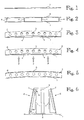
- Figures 1 to 5 show the method of the invention in a set of figures shown in steps.
- reference numeral 1 marks the base plate of the beam
- reference numeral 2 marks the web parts
- reference numeral 3 marks the top plate.
- Figures 1 to 5 only show one web plate. However, a finished beam has two web plates, as shown in Figure 6 , for instance.
- the base plate 1 of the beam is first placed on a platform, as shown in Figure 1 .
- side supports 4 determining the position of the web parts 2, i.e. the web plates and centre supports 5 determining the location of the top plate are fastened to the base plate at regular intervals in the longitudinal direction.
- the side supports 4 and centre supports 5 are clearly shown in Figure 6 .
- the fastening of the side supports 4 and centre supports 5 to the base plate is shown generally in Figure 2 .
- the top plate 3 can also be set in place on the centre supports 5, as shown in Figure 2 .
- the web plates 2 are placed on the side supports 4.
- the web plates 2 are cut to a curved shape according to the pre-cambering of the beam.
- the curved shape of the web plate is shown exaggerated.
- Setting the web plates 2 on the base plate 1 is shown in Figure 3 .
- openings 6 are also made to the web plates 2, through which concrete can be fed inside the beam.
- a force is directed to the base plate that forces the base plate 1 to the curvature determined by the web plates 2, whereby the side supports 4 determine the position of the web plates 2 and, because the centre supports move with the base plate to the position according to the curvature of the web plates, the centre supports 5 determine the curvature of the top plate 3.
- the above-mentioned force is marked with arrows F in Figure 4 .
- the base plate 1, web plates 2 and top plate 3 are fastened together by welding to obtain the beam shown in Figure 5 .
- the beam can also be equipped with end plates to close the ends of the beam.
- the end plates are not shown in Figures 1 to 5 .
- the end plates are fastened to the beam by welding.
- the end plates are shown by way of example in Figure 7 and marked with reference numeral 7.
- the method of the invention described above is particularly advantageous in that the manufacture of the beam is done without expensive jigs that were earlier used in the manufacture of beams.
- the above-mentioned side supports 4 are formed in such a manner that they comprise a part to be fastened to the base plate and having a first end 4a arranged to determine the location of the low edge of the web plate and a second end 4b arranged to determine the location of the top edge of the web plate.
- the side supports 4 can in principle be made in any shape.
- a particularly advantageous solution is one in which the part to be fastened to the base plate is substantially L-shaped and the free ends 4a, 4b of its branches are arranged to form the ends determining the locations of the edges of the web plate 2.
- the outer surface of one branch is arranged to serve as the fastening surface between the part and the base plate 1. This type of application is shown in Figure 6 .
- the side supports 4 can be fastened to the base plate 1 by welding, for instance.
- the side supports 4 can be cut from a plate-like material, such as steel plate.
- the L-shaped side supports used in the embodiment of Figure 6 are made in this manner.
- the centre supports 5 can be made in the same manner as the side supports 4.
- the shape of the centre supports 5 can also vary; in the embodiment of Figure 6 , the centre supports are separate, substantially rectangular pieces. It is, however, possible to make the supports in such a manner that the side support and centre support are made up of one and the same element, if this is considered necessary.
- the side supports and/or centre supports can also be made of a bar-like material, etc.
Landscapes
- Engineering & Computer Science (AREA)
- Architecture (AREA)
- Civil Engineering (AREA)
- Structural Engineering (AREA)
- Chemical & Material Sciences (AREA)
- Composite Materials (AREA)
- Electromagnetism (AREA)
- Physics & Mathematics (AREA)
- Rod-Shaped Construction Members (AREA)
- Roof Covering Using Slabs Or Stiff Sheets (AREA)
- Welding Or Cutting Using Electron Beams (AREA)
- Catalysts (AREA)
- Floor Finish (AREA)
Claims (5)
- Verfahren zur Herstellung eines Stahlträgers, der zusammen mit Beton als eine stützende Verbundkonstruktion für unterschiedliche Plattensysteme fungiert, bei welchem Verfahren eine Grundplatte (1), Stegteile (2) und eine Oberplatte (3) des Trägers aus einem Plattenmaterial geschnitten werden, die oben erwähnten Teile derart montiert werden, dass zwischen den Teilen ein Raum für durch Öffnungen (6) im Stegteil (2) zuzuführenden Beton ausgebildet wird, und die Teile zusammengeschweisst werden, dadurch gekennzeichnet, dass die Stegteile (2) in eine gekrümmte Form gemäß einer Vorwölbung geschnitten werden, dass die Position der Stegteile (2) bestimmende Seitenstützen (4) und die Lage der Oberplatte (3) bestimmende Mittelstützen (5) an die Grundplatte (1) in regelmäßigen Abständen in Längsrichtung des Trägers befestigt werden, dass eine Kraft (F) auf die Grundplatte (1) gerichtet wird, die die Grundplatte (1) zur von den Stegteilen (2) bestimmten Krümmung zwingt, so dass die Seitenstützen (4) die Position der Stegteile (2) bestimmen und die Mittelstützen (5) die Krümmung der an ihren Platz zu stellenden Oberplatte (3) bestimmen.
- Verfahren nach Anspruch 2, dadurch gekennzeichnet, dass die Seitenstützen (4) und die Mittelstützen (5) an die Grundplatte (1) geschweisst werden.
- Stahlträger, der vorgesehen ist, zusammen mit Beton als eine stützende Verbundkonstruktion für unterschiedliche Plattensysteme zu fungieren, welcher Stahlträger eine Grundplatte (1), Stegteile (2) und eine Oberplatte (3) ausweist, die aus einem Plattenmaterial geschnitten sind, wobei die Grundplatte (1), die Stegteile (2) und die Oberplatte (3) derart montiert und zusammengeschweisst sind, dass zwischen den Teilen ein Raum für durch Öffnungen (6) im Stegteil (2) zuzuführenden Beton ausgebildet wird, dadurch gekennzeichnet, dass die Stegteile (2) in eine gekrümmte Form gemäß einer Vorwölbung geschnitten sind, die Position der Stegteile (2) bestimmende Seitenstützen (4) und die Lage der Oberplatte (3) bestimmende Mittelstützen (5) an die Grundplatte (1) in regelmäßigen Abständen in Längsrichtung des Trägers befestigt werden, dass die Grundplatte (1) zur von den Stegteilen (2) bestimmten Krümmung gezwungen ist, wobei die Seitenstützen (4) vorgesehen sind, die Position der Stegteile (2) zu bestimmen, und die Mittelstützen (5) vorgesehen sind, die Krümmung der Oberplatte (3) zu bestimmen.
- Stahlträger nach Anspruch 3, dadurch gekennzeichnet, dass die Seitenstütze (4) einen an die Grundplatte zu befestigenden Teil aufweist und ein erstes Ende (4a) hat, das angeordnet ist, die Lage des unteren Rands des Stegteils (2) zu bestimmen, und ein zweites Ende (4b) hat, das angeordnet ist, die Lage des oberen Rands des Stegteils (2) zu bestimmen.
- Stahlträger nach Anspruch 4, dadurch gekennzeichnet, dass die Seitenstütze (4) ein wesentlich L-förmiger Teil ist und die freien Enden (4a, 4b) seiner Schenkel vorgesehen sind, die Enden auszubilden, die die Lage der Ränder des Stegteils (2) bestimmen, und dass die Aussenfläche eines Endes vorgesehen ist, als Befestigungsfläche zwischen der Seitenstütze (4) und der Grundplatte (1) zu dienen.
Applications Claiming Priority (3)
| Application Number | Priority Date | Filing Date | Title |
|---|---|---|---|
| FI20021009A FI118816B (fi) | 2002-05-29 | 2002-05-29 | Menetelmä ja väline teräspalkin valmistamiseksi |
| FI20021009 | 2002-05-29 | ||
| PCT/FI2003/000398 WO2003100186A1 (en) | 2002-05-29 | 2003-05-23 | Method and means for manufacturing steel beam |
Publications (2)
| Publication Number | Publication Date |
|---|---|
| EP1507938A1 EP1507938A1 (de) | 2005-02-23 |
| EP1507938B1 true EP1507938B1 (de) | 2010-03-24 |
Family
ID=8564024
Family Applications (1)
| Application Number | Title | Priority Date | Filing Date |
|---|---|---|---|
| EP03725251A Expired - Lifetime EP1507938B1 (de) | 2002-05-29 | 2003-05-23 | Verfahren zur herstellung eines stahlträgers und stahlträger |
Country Status (9)
| Country | Link |
|---|---|
| EP (1) | EP1507938B1 (de) |
| AT (1) | ATE462051T1 (de) |
| AU (1) | AU2003227799A1 (de) |
| DE (1) | DE60331828D1 (de) |
| DK (1) | DK1507938T3 (de) |
| ES (1) | ES2340674T3 (de) |
| FI (1) | FI118816B (de) |
| NO (1) | NO331600B1 (de) |
| WO (1) | WO2003100186A1 (de) |
Cited By (3)
| Publication number | Priority date | Publication date | Assignee | Title |
|---|---|---|---|---|
| CN104032893A (zh) * | 2014-06-26 | 2014-09-10 | 南京工业大学 | 一种用于组合梁的一体成型的frp折线形板结构 |
| WO2021141297A1 (ko) * | 2020-01-08 | 2021-07-15 | (주)센벡스 | 강콘크리트 합성보용 강판 조립보 |
| EP4435193A3 (de) * | 2017-03-07 | 2025-01-15 | NXT Building System Pty Ltd. | Gebäudesystem |
Families Citing this family (6)
| Publication number | Priority date | Publication date | Assignee | Title |
|---|---|---|---|---|
| CN102635198B (zh) * | 2012-04-09 | 2014-10-08 | 浙江东南网架股份有限公司 | 一种组合椭圆形截面构件及其加工方法 |
| FI20145669A7 (fi) | 2014-07-11 | 2016-01-12 | Peikko Group Oy | Teräspalkki |
| FI126697B (fi) | 2015-11-13 | 2017-04-13 | Anstar Oy | Menetelmä teräspalkin valmistamistamiseksi |
| CN113530051B (zh) * | 2021-07-12 | 2022-11-01 | 台州普立德建筑科技有限公司 | 一种预制不出筋叠合板 |
| WO2023021238A1 (en) | 2021-08-20 | 2023-02-23 | Peikko Group Oy | Steel beam and method for producing a steel-concrete composite beam |
| CN115446555B (zh) * | 2022-10-08 | 2024-05-07 | 上海宝冶工程技术有限公司 | 一种管型行车起重梁的制作方法 |
Citations (2)
| Publication number | Priority date | Publication date | Assignee | Title |
|---|---|---|---|---|
| US679430A (en) * | 1900-03-29 | 1901-07-30 | Jacob Schratwieser | Floor and ceiling construction. |
| AT221782B (de) * | 1960-02-25 | 1962-06-12 | Mauro Fioretto | Form mit veränderbarem Querschnitt, insbesondere für die Einschalung von Bauteilen, wie Pfeilern od. dgl. |
Family Cites Families (3)
| Publication number | Priority date | Publication date | Assignee | Title |
|---|---|---|---|---|
| GB1407976A (en) * | 1971-09-07 | 1975-10-01 | Catnic Components Ltd | Lintels |
| FI85745C (fi) | 1989-04-13 | 1993-02-23 | Peikkorakenne Oy | Brandsaeker prefabricerad staolbalk |
| FI92089C (fi) | 1993-01-13 | 1994-09-26 | Deltatek Oy | Esivalmistettu teräs-betoni-liittopalkki |
-
2002
- 2002-05-29 FI FI20021009A patent/FI118816B/fi not_active IP Right Cessation
-
2003
- 2003-05-23 AT AT03725251T patent/ATE462051T1/de active
- 2003-05-23 WO PCT/FI2003/000398 patent/WO2003100186A1/en not_active Ceased
- 2003-05-23 AU AU2003227799A patent/AU2003227799A1/en not_active Abandoned
- 2003-05-23 DE DE60331828T patent/DE60331828D1/de not_active Expired - Lifetime
- 2003-05-23 ES ES03725251T patent/ES2340674T3/es not_active Expired - Lifetime
- 2003-05-23 DK DK03725251.7T patent/DK1507938T3/da active
- 2003-05-23 EP EP03725251A patent/EP1507938B1/de not_active Expired - Lifetime
-
2004
- 2004-12-29 NO NO20045686A patent/NO331600B1/no not_active IP Right Cessation
Patent Citations (2)
| Publication number | Priority date | Publication date | Assignee | Title |
|---|---|---|---|---|
| US679430A (en) * | 1900-03-29 | 1901-07-30 | Jacob Schratwieser | Floor and ceiling construction. |
| AT221782B (de) * | 1960-02-25 | 1962-06-12 | Mauro Fioretto | Form mit veränderbarem Querschnitt, insbesondere für die Einschalung von Bauteilen, wie Pfeilern od. dgl. |
Cited By (5)
| Publication number | Priority date | Publication date | Assignee | Title |
|---|---|---|---|---|
| CN104032893A (zh) * | 2014-06-26 | 2014-09-10 | 南京工业大学 | 一种用于组合梁的一体成型的frp折线形板结构 |
| CN104032893B (zh) * | 2014-06-26 | 2016-03-23 | 南京工业大学 | 一种用于组合梁的一体成型的frp折线形板结构 |
| EP4435193A3 (de) * | 2017-03-07 | 2025-01-15 | NXT Building System Pty Ltd. | Gebäudesystem |
| WO2021141297A1 (ko) * | 2020-01-08 | 2021-07-15 | (주)센벡스 | 강콘크리트 합성보용 강판 조립보 |
| US12123191B2 (en) | 2020-01-08 | 2024-10-22 | Senvex Co., Ltd. | Steel plate built-up beam for steel-concrete composite beam |
Also Published As
| Publication number | Publication date |
|---|---|
| NO20045686L (no) | 2004-12-29 |
| DK1507938T3 (da) | 2010-07-12 |
| ES2340674T3 (es) | 2010-06-08 |
| ATE462051T1 (de) | 2010-04-15 |
| WO2003100186A1 (en) | 2003-12-04 |
| EP1507938A1 (de) | 2005-02-23 |
| DE60331828D1 (de) | 2010-05-06 |
| NO331600B1 (no) | 2012-02-06 |
| FI20021009A0 (fi) | 2002-05-29 |
| AU2003227799A1 (en) | 2003-12-12 |
| FI20021009A7 (fi) | 2003-11-30 |
| FI118816B (fi) | 2008-03-31 |
Similar Documents
| Publication | Publication Date | Title |
|---|---|---|
| US20090100794A1 (en) | Floor construction method and system | |
| WO2003100186A1 (en) | Method and means for manufacturing steel beam | |
| EP1507937B1 (de) | Stahlträger | |
| EP1507939B1 (de) | Stahlträger | |
| KR101162180B1 (ko) | 단부판이 구비된 성형강판 조립보 및 그를 이용한 장스팬용 강콘크리트 합성보 | |
| US5809735A (en) | Steel-wood system | |
| JP4943747B2 (ja) | 鋼管柱の柱脚構造及び建方方法 | |
| AU2020251195B2 (en) | Column shoe manufactured from one piece of sheet metal | |
| JP2019157518A (ja) | 梯子型耐力壁架構 | |
| CN113186794A (zh) | 一种波形钢腹板钢混组合预应力箱梁施工工法 | |
| JP2022047017A (ja) | 柱と梁との接合構造 | |
| JPH07324419A (ja) | フラットスラブ構造 | |
| JPH0932287A (ja) | パイプ類挿通孔の隙間埋め充填材の支持方法及び支持具 | |
| FI131215B1 (en) | Method for producing a steel beam and steel beam | |
| JP4120734B2 (ja) | 鉄骨構造物の柱脚構造 | |
| CN223469026U (zh) | 一种楼承板的支撑底板及曲面屋盖浇筑模板 | |
| JPH10152888A (ja) | プレキャスト鉄筋コンクリート部材の接続構造 | |
| EP1099805B1 (de) | Tragkonstruktion | |
| JPS5830891Y2 (ja) | 構造用鋼材 | |
| JPH07189337A (ja) | 鉄筋コンクリート柱と鉄骨梁との接合部構造 | |
| KR20020096773A (ko) | 철 골조용 형강 구조 | |
| CZ98298A3 (cs) | Způsob montáže deskovitého izolačního materiálu a materiál pro jeho provádění | |
| GB2269609A (en) | Shearhead with inclined surfaces | |
| JPH08189122A (ja) | 鉄骨造り建造物の床レベル調整方法 | |
| JP2021161757A (ja) | 梁際治具 |
Legal Events
| Date | Code | Title | Description |
|---|---|---|---|
| PUAI | Public reference made under article 153(3) epc to a published international application that has entered the european phase |
Free format text: ORIGINAL CODE: 0009012 |
|
| 17P | Request for examination filed |
Effective date: 20041122 |
|
| AK | Designated contracting states |
Kind code of ref document: A1 Designated state(s): AT BE BG CH CY CZ DE DK EE ES FI FR GB GR HU IE IT LI LU MC NL PT RO SE SI SK TR |
|
| AX | Request for extension of the european patent |
Extension state: AL LT LV MK |
|
| DAX | Request for extension of the european patent (deleted) | ||
| 17Q | First examination report despatched |
Effective date: 20090325 |
|
| GRAP | Despatch of communication of intention to grant a patent |
Free format text: ORIGINAL CODE: EPIDOSNIGR1 |
|
| RTI1 | Title (correction) |
Free format text: METHOD FOR MANUFACTURING STEEL BEAM AND STEEL BEAM |
|
| GRAS | Grant fee paid |
Free format text: ORIGINAL CODE: EPIDOSNIGR3 |
|
| RAP1 | Party data changed (applicant data changed or rights of an application transferred) |
Owner name: PEIKKO GROUP OY |
|
| GRAA | (expected) grant |
Free format text: ORIGINAL CODE: 0009210 |
|
| AK | Designated contracting states |
Kind code of ref document: B1 Designated state(s): AT BE BG CH CY CZ DE DK EE ES FI FR GB GR HU IE IT LI LU MC NL PT RO SE SI SK TR |
|
| REG | Reference to a national code |
Ref country code: GB Ref legal event code: FG4D |
|
| REG | Reference to a national code |
Ref country code: CH Ref legal event code: EP |
|
| REG | Reference to a national code |
Ref country code: IE Ref legal event code: FG4D |
|
| REF | Corresponds to: |
Ref document number: 60331828 Country of ref document: DE Date of ref document: 20100506 Kind code of ref document: P |
|
| REG | Reference to a national code |
Ref country code: CH Ref legal event code: NV Representative=s name: N&G PATENT SERVICES SA |
|
| REG | Reference to a national code |
Ref country code: ES Ref legal event code: FG2A Ref document number: 2340674 Country of ref document: ES Kind code of ref document: T3 |
|
| REG | Reference to a national code |
Ref country code: NL Ref legal event code: T3 |
|
| REG | Reference to a national code |
Ref country code: GR Ref legal event code: EP Ref document number: 20100401172 Country of ref document: GR |
|
| REG | Reference to a national code |
Ref country code: DK Ref legal event code: T3 |
|
| REG | Reference to a national code |
Ref country code: SE Ref legal event code: TRGR |
|
| REG | Reference to a national code |
Ref country code: SK Ref legal event code: T3 Ref document number: E 7197 Country of ref document: SK |
|
| PG25 | Lapsed in a contracting state [announced via postgrant information from national office to epo] |
Ref country code: FI Free format text: LAPSE BECAUSE OF FAILURE TO SUBMIT A TRANSLATION OF THE DESCRIPTION OR TO PAY THE FEE WITHIN THE PRESCRIBED TIME-LIMIT Effective date: 20100324 Ref country code: SI Free format text: LAPSE BECAUSE OF FAILURE TO SUBMIT A TRANSLATION OF THE DESCRIPTION OR TO PAY THE FEE WITHIN THE PRESCRIBED TIME-LIMIT Effective date: 20100324 |
|
| REG | Reference to a national code |
Ref country code: HU Ref legal event code: AG4A Ref document number: E008262 Country of ref document: HU |
|
| PG25 | Lapsed in a contracting state [announced via postgrant information from national office to epo] |
Ref country code: EE Free format text: LAPSE BECAUSE OF FAILURE TO SUBMIT A TRANSLATION OF THE DESCRIPTION OR TO PAY THE FEE WITHIN THE PRESCRIBED TIME-LIMIT Effective date: 20100324 Ref country code: RO Free format text: LAPSE BECAUSE OF FAILURE TO SUBMIT A TRANSLATION OF THE DESCRIPTION OR TO PAY THE FEE WITHIN THE PRESCRIBED TIME-LIMIT Effective date: 20100324 |
|
| PG25 | Lapsed in a contracting state [announced via postgrant information from national office to epo] |
Ref country code: BG Free format text: LAPSE BECAUSE OF FAILURE TO SUBMIT A TRANSLATION OF THE DESCRIPTION OR TO PAY THE FEE WITHIN THE PRESCRIBED TIME-LIMIT Effective date: 20100624 |
|
| PG25 | Lapsed in a contracting state [announced via postgrant information from national office to epo] |
Ref country code: MC Free format text: LAPSE BECAUSE OF NON-PAYMENT OF DUE FEES Effective date: 20100531 |
|
| PLBE | No opposition filed within time limit |
Free format text: ORIGINAL CODE: 0009261 |
|
| STAA | Information on the status of an ep patent application or granted ep patent |
Free format text: STATUS: NO OPPOSITION FILED WITHIN TIME LIMIT |
|
| PG25 | Lapsed in a contracting state [announced via postgrant information from national office to epo] |
Ref country code: PT Free format text: LAPSE BECAUSE OF FAILURE TO SUBMIT A TRANSLATION OF THE DESCRIPTION OR TO PAY THE FEE WITHIN THE PRESCRIBED TIME-LIMIT Effective date: 20100726 |
|
| 26N | No opposition filed |
Effective date: 20101228 |
|
| PG25 | Lapsed in a contracting state [announced via postgrant information from national office to epo] |
Ref country code: IT Free format text: LAPSE BECAUSE OF NON-PAYMENT OF DUE FEES Effective date: 20100523 |
|
| PG25 | Lapsed in a contracting state [announced via postgrant information from national office to epo] |
Ref country code: IE Free format text: LAPSE BECAUSE OF NON-PAYMENT OF DUE FEES Effective date: 20100523 |
|
| PGRI | Patent reinstated in contracting state [announced from national office to epo] |
Ref country code: IT Effective date: 20110616 |
|
| PG25 | Lapsed in a contracting state [announced via postgrant information from national office to epo] |
Ref country code: CY Free format text: LAPSE BECAUSE OF FAILURE TO SUBMIT A TRANSLATION OF THE DESCRIPTION OR TO PAY THE FEE WITHIN THE PRESCRIBED TIME-LIMIT Effective date: 20100324 |
|
| PG25 | Lapsed in a contracting state [announced via postgrant information from national office to epo] |
Ref country code: LU Free format text: LAPSE BECAUSE OF NON-PAYMENT OF DUE FEES Effective date: 20100523 |
|
| REG | Reference to a national code |
Ref country code: FR Ref legal event code: PLFP Year of fee payment: 14 |
|
| REG | Reference to a national code |
Ref country code: FR Ref legal event code: PLFP Year of fee payment: 15 |
|
| REG | Reference to a national code |
Ref country code: FR Ref legal event code: PLFP Year of fee payment: 16 |
|
| PG25 | Lapsed in a contracting state [announced via postgrant information from national office to epo] |
Ref country code: GR Free format text: LAPSE BECAUSE OF NON-PAYMENT OF DUE FEES Effective date: 20181204 |
|
| PGFP | Annual fee paid to national office [announced via postgrant information from national office to epo] |
Ref country code: TR Payment date: 20190503 Year of fee payment: 17 Ref country code: HU Payment date: 20190507 Year of fee payment: 17 Ref country code: FR Payment date: 20190520 Year of fee payment: 17 |
|
| PGFP | Annual fee paid to national office [announced via postgrant information from national office to epo] |
Ref country code: SK Payment date: 20190424 Year of fee payment: 17 Ref country code: CH Payment date: 20190516 Year of fee payment: 17 |
|
| PGFP | Annual fee paid to national office [announced via postgrant information from national office to epo] |
Ref country code: AT Payment date: 20190527 Year of fee payment: 17 Ref country code: GB Payment date: 20190520 Year of fee payment: 17 |
|
| REG | Reference to a national code |
Ref country code: AT Ref legal event code: MM01 Ref document number: 462051 Country of ref document: AT Kind code of ref document: T Effective date: 20200523 |
|
| REG | Reference to a national code |
Ref country code: SK Ref legal event code: MM4A Ref document number: E 7197 Country of ref document: SK Effective date: 20200523 |
|
| PG25 | Lapsed in a contracting state [announced via postgrant information from national office to epo] |
Ref country code: HU Free format text: LAPSE BECAUSE OF NON-PAYMENT OF DUE FEES Effective date: 20200524 Ref country code: LI Free format text: LAPSE BECAUSE OF NON-PAYMENT OF DUE FEES Effective date: 20200531 Ref country code: CH Free format text: LAPSE BECAUSE OF NON-PAYMENT OF DUE FEES Effective date: 20200531 Ref country code: AT Free format text: LAPSE BECAUSE OF NON-PAYMENT OF DUE FEES Effective date: 20200523 |
|
| PG25 | Lapsed in a contracting state [announced via postgrant information from national office to epo] |
Ref country code: SK Free format text: LAPSE BECAUSE OF NON-PAYMENT OF DUE FEES Effective date: 20200523 |
|
| REG | Reference to a national code |
Ref country code: BE Ref legal event code: MM Effective date: 20200531 |
|
| GBPC | Gb: european patent ceased through non-payment of renewal fee |
Effective date: 20200523 |
|
| PG25 | Lapsed in a contracting state [announced via postgrant information from national office to epo] |
Ref country code: GB Free format text: LAPSE BECAUSE OF NON-PAYMENT OF DUE FEES Effective date: 20200523 Ref country code: FR Free format text: LAPSE BECAUSE OF NON-PAYMENT OF DUE FEES Effective date: 20200531 |
|
| PG25 | Lapsed in a contracting state [announced via postgrant information from national office to epo] |
Ref country code: BE Free format text: LAPSE BECAUSE OF NON-PAYMENT OF DUE FEES Effective date: 20200531 |
|
| REG | Reference to a national code |
Ref country code: ES Ref legal event code: FD2A Effective date: 20211004 |
|
| PG25 | Lapsed in a contracting state [announced via postgrant information from national office to epo] |
Ref country code: ES Free format text: LAPSE BECAUSE OF NON-PAYMENT OF DUE FEES Effective date: 20200524 |
|
| PG25 | Lapsed in a contracting state [announced via postgrant information from national office to epo] |
Ref country code: TR Free format text: LAPSE BECAUSE OF NON-PAYMENT OF DUE FEES Effective date: 20200523 |
|
| PGFP | Annual fee paid to national office [announced via postgrant information from national office to epo] |
Ref country code: NL Payment date: 20220506 Year of fee payment: 20 |
|
| PGFP | Annual fee paid to national office [announced via postgrant information from national office to epo] |
Ref country code: SE Payment date: 20220517 Year of fee payment: 20 Ref country code: DK Payment date: 20220517 Year of fee payment: 20 Ref country code: DE Payment date: 20220519 Year of fee payment: 20 Ref country code: CZ Payment date: 20220427 Year of fee payment: 20 |
|
| PG25 | Lapsed in a contracting state [announced via postgrant information from national office to epo] |
Ref country code: IT Free format text: LAPSE BECAUSE OF NON-PAYMENT OF DUE FEES Effective date: 20200523 |
|
| REG | Reference to a national code |
Ref country code: DE Ref legal event code: R071 Ref document number: 60331828 Country of ref document: DE |
|
| REG | Reference to a national code |
Ref country code: NL Ref legal event code: MK Effective date: 20230522 |
|
| REG | Reference to a national code |
Ref country code: DK Ref legal event code: EUP Expiry date: 20230523 |
|
| P01 | Opt-out of the competence of the unified patent court (upc) registered |
Effective date: 20230519 |
|
| REG | Reference to a national code |
Ref country code: SE Ref legal event code: EUG |
|
| PG25 | Lapsed in a contracting state [announced via postgrant information from national office to epo] |
Ref country code: CZ Free format text: LAPSE BECAUSE OF EXPIRATION OF PROTECTION Effective date: 20230523 |