EP1508032B1 - Rauchmelder - Google Patents
Rauchmelder Download PDFInfo
- Publication number
- EP1508032B1 EP1508032B1 EP03725408A EP03725408A EP1508032B1 EP 1508032 B1 EP1508032 B1 EP 1508032B1 EP 03725408 A EP03725408 A EP 03725408A EP 03725408 A EP03725408 A EP 03725408A EP 1508032 B1 EP1508032 B1 EP 1508032B1
- Authority
- EP
- European Patent Office
- Prior art keywords
- radiation
- chamber
- smoke
- detector according
- particles
- Prior art date
- Legal status (The legal status is an assumption and is not a legal conclusion. Google has not performed a legal analysis and makes no representation as to the accuracy of the status listed.)
- Expired - Lifetime
Links
Images




Classifications
-
- G—PHYSICS
- G08—SIGNALLING
- G08B—SIGNALLING SYSTEMS, e.g. PERSONAL CALLING SYSTEMS; ORDER TELEGRAPHS; ALARM SYSTEMS
- G08B29/00—Checking or monitoring of signalling or alarm systems; Prevention or correction of operating errors, e.g. preventing unauthorised operation
- G08B29/18—Prevention or correction of operating errors
- G08B29/183—Single detectors using dual technologies
-
- G—PHYSICS
- G01—MEASURING; TESTING
- G01N—INVESTIGATING OR ANALYSING MATERIALS BY DETERMINING THEIR CHEMICAL OR PHYSICAL PROPERTIES
- G01N21/00—Investigating or analysing materials by the use of optical means, i.e. using sub-millimetre waves, infrared, visible or ultraviolet light
- G01N21/01—Arrangements or apparatus for facilitating the optical investigation
- G01N21/03—Cuvette constructions
- G01N21/0303—Optical path conditioning in cuvettes, e.g. windows; adapted optical elements or systems; path modifying or adjustment
-
- G—PHYSICS
- G01—MEASURING; TESTING
- G01N—INVESTIGATING OR ANALYSING MATERIALS BY DETERMINING THEIR CHEMICAL OR PHYSICAL PROPERTIES
- G01N21/00—Investigating or analysing materials by the use of optical means, i.e. using sub-millimetre waves, infrared, visible or ultraviolet light
- G01N21/17—Systems in which incident light is modified in accordance with the properties of the material investigated
- G01N21/47—Scattering, i.e. diffuse reflection
- G01N21/49—Scattering, i.e. diffuse reflection within a body or fluid
- G01N21/53—Scattering, i.e. diffuse reflection within a body or fluid within a flowing fluid, e.g. smoke
- G01N21/534—Scattering, i.e. diffuse reflection within a body or fluid within a flowing fluid, e.g. smoke by measuring transmission alone, i.e. determining opacity
-
- G—PHYSICS
- G08—SIGNALLING
- G08B—SIGNALLING SYSTEMS, e.g. PERSONAL CALLING SYSTEMS; ORDER TELEGRAPHS; ALARM SYSTEMS
- G08B17/00—Fire alarms; Alarms responsive to explosion
- G08B17/10—Actuation by presence of smoke or gases, e.g. automatic alarm devices for analysing flowing fluid materials by the use of optical means
- G08B17/103—Actuation by presence of smoke or gases, e.g. automatic alarm devices for analysing flowing fluid materials by the use of optical means using a light emitting and receiving device
-
- G—PHYSICS
- G08—SIGNALLING
- G08B—SIGNALLING SYSTEMS, e.g. PERSONAL CALLING SYSTEMS; ORDER TELEGRAPHS; ALARM SYSTEMS
- G08B17/00—Fire alarms; Alarms responsive to explosion
- G08B17/10—Actuation by presence of smoke or gases, e.g. automatic alarm devices for analysing flowing fluid materials by the use of optical means
- G08B17/103—Actuation by presence of smoke or gases, e.g. automatic alarm devices for analysing flowing fluid materials by the use of optical means using a light emitting and receiving device
- G08B17/107—Actuation by presence of smoke or gases, e.g. automatic alarm devices for analysing flowing fluid materials by the use of optical means using a light emitting and receiving device for detecting light-scattering due to smoke
-
- G—PHYSICS
- G08—SIGNALLING
- G08B—SIGNALLING SYSTEMS, e.g. PERSONAL CALLING SYSTEMS; ORDER TELEGRAPHS; ALARM SYSTEMS
- G08B17/00—Fire alarms; Alarms responsive to explosion
- G08B17/10—Actuation by presence of smoke or gases, e.g. automatic alarm devices for analysing flowing fluid materials by the use of optical means
- G08B17/11—Actuation by presence of smoke or gases, e.g. automatic alarm devices for analysing flowing fluid materials by the use of optical means using an ionisation chamber for detecting smoke or gas
- G08B17/113—Constructional details
-
- G—PHYSICS
- G01—MEASURING; TESTING
- G01N—INVESTIGATING OR ANALYSING MATERIALS BY DETERMINING THEIR CHEMICAL OR PHYSICAL PROPERTIES
- G01N2201/00—Features of devices classified in G01N21/00
- G01N2201/06—Illumination; Optics
- G01N2201/065—Integrating spheres
Definitions
- the present invention relates to particle detectors and to a method of detecting particles - particularly, but not exclusively, smoke particles.
- Obscuration, or direct, detectors have an emitter of suitable electromagnetic radiation, such as visible light, aligned with a detector for the radiation such that a beam of the radiation generated by the emitter shines directly into the detector through a volume in which the particles may be present.
- This type of detector thus measures the radiation lost from the beam, along a known path-length, across the volume containing the smoke, and is commonly measured as %/m of radiation lost.
- the radiation is lost from the beam by a combination of reflection, scattering and absorption in the smoke particles.
- Obscuration detectors typically work well for black smoke but are less sensitive to white or grey smoke. Additionally, obscuration detectors typically are not housed within a chamber, as they have an emitter and a detector spaced at a substantial distance, such as 1m, to provide adequate sensitivity.
- Indirect or reflected detectors commonly called scattering detectors
- scattering detectors have an emitter and detector positioned on non-co-linear axes such that the radiation from the emitter does not shine directly onto the detector.
- Smoke particles reflect or scatter light from the emitter into the receiver.
- Scattering detectors generally work well for white or grey smoke but have a decreased sensitivity to black smoke.
- Obscuration detectors that make a measurement of light transmission through the smoke are used extensively in beam smoke detectors but not in point smoke detectors because the path lengths available are relatively short, without complicated optical arrangements which can be prone to contamination, and this places great demands on the stability of the measurement. For instance, to obtain a sensitivity of 10%/m over a path length of 10 cm, a transmitted signal change of 1% would have to be detected.
- US Patent No. 4,857,895 discloses a smoke detector having a double pass absorption path across an enclosed volume achieved by a lens or mirror. A second detector, placed at an approximate right angle to the beam, detects the scattered light. The intention of the device is to increase the black smoke sensitivity. There is also provision for separate light sources for the obscuration measurement and for the scatter measurement and it is disclosed that a green LED provides better obscuration sensitivity whereas the scatter LED can be a conventional infrared LED. Alarm is generated by either the scatter or obscuration signal passing through simple thresholds or, alternatively, if the difference in the two signals exceeds a threshold.
- US Patent No. 6,225,910 and US Patent Application No. 2001 020899 also disclose obscuration devices and scattering devices in the same housing.
- the two documents disclose various optical arrangements to increase the obscuration path length. The arrangements involve single and multiple specular reflections from a mirror or mirrors.
- US Patent No. 6,225,910 for the obscuration measurement to be in the blue/green and the scatter measurement to be in the infrared.
- CH 607687 discloses a smoke detector comprising a spherical measuring chamber which has an internal surface constructed to reflect radiation in a diffuse fashion. Radiation scattered from a light beam by the presence of smoke particles is detected by the detector.
- a chamber having a substantially high reflectivity substantially Lambertian surface and for receiving particles, radiation emitting means for emitting radiation into the chamber and radiation detecting means for detecting the effect of the particles on the radiation within the chamber, characterised in that the radiation detecting means is primarily for detecting absorption of the radiation by the particles, and the radiation detecting means has a wide viewing angle to receive radiation directly from a substantial portion of the high reflectivity Lambertian surface which surface is directly irradiated by the radiation emitting means.
- a particle detecting method including the steps of providing a chamber having a substantially high reflectivity substantially Lambertian surface and for receiving particles, emitting radiation into the chamber, and detecting the effect of the particles on the radiation within the chamber; characterised in that the step of detecting radiation includes detecting the absorption of radiation by receiving radiation directly from a substantial portion of the high reflectivity Lambertian surface which surface is directly irradiated by the radiation emitting means.
- the chamber is an integrating sphere.
- This is a spherical cavity into which light or other radiation is directed.
- the internal surfaces of the cavity are coated with as, near as possible, a high reflectivity (for example, greater than 90%) Lambertian scattering material, that is a material that efficiently scatters incident light equally in all directions at all wavelengths.
- the material commonly used is barium sulphate but most matt white paints are approximately Lambertian.
- a detector views the internal surface of the sphere but not the source directly, and therefore light reaching the detector has followed a multiplicity of paths within the sphere and has probably been scattered several times from the walls before reaching the detector. If absorbing particles (such as black smoke) are introduced into the sphere, the detected signal is reduced.
- One advantage of the integrating sphere of the embodiments being described is that several different light sources can be mounted in the sphere at relatively arbitrary positions, allowing measurements to be made at two or more wavelengths with one detector by frequency or time division multiplexing. Also, there are no critical alignments in the system and the scattering surface is substantially all of the internal surface of the sphere, so it should be relatively insensitive to localised contamination.
- a potential disadvantage of the integrating sphere arrangement is its relative insensitivity to white/grey smoke.
- a second detector mounted in or on the internal surface of the chamber, which is arranged so that it is mainly sensitive to scattered light (that is, it is not directly aligned with the radiation source(s)).
- the addition of this detector compromises the performance of the integrating sphere to some extent, as the part of the surface of the sphere that this detector views is made black to reduce the background signal, in the absence of smoke, to a manageable level.
- holes must also be included in the sphere to allow smoke to enter and it is advantageous to locate these holes in the black part of the sphere to minimise the disturbance to the integrating sphere.
- the smoke detector 1 comprises a hollow sphere 2 machined from aluminium alloy (or other suitable material) with an internal diameter in this example of 50mm. Most of the internal surface 3 of the detector 1 is coated with a material in order to provide the surfaces so coated with a substantially high reflectivity (greater than 90%) Lambertian surface. A suitable material is barium sulphate.
- a scattering detector 9 for example an NSL710 silicon photodiode, is mounted on the exterior surface of the sphere 2 opposite the integrating detector 5 and is lensed so that it has a restricted viewing angle through aperture 11.
- a black painted region 13 of the internal surface of the sphere surrounds the integrating detector 5.
- One suitable black paint has the trade name Nextel and is manufactured by Mankiewicz Gebr. and Co. in Germany. This region 13 also contains six 5mm diameter holes 15 to allow smoke access to the spherical cavity. There are also additional holes 17 at 90° from the integrating detector to allow flow through the cavity.
- Two 5mm diameter, plastic encapsulated LEDs 19,21 are mounted in apertures in the sphere 2 at 45° from the integrating detector 5 position.
- One is an RS 235-9922 470nm blue LED 19, which is lensed such that it has a + or - 15° beam spread.
- the second is a Siemens LD274-3 950nm infrared LED 21, which is lensed to give a + or - 10° beam spread.
- the beam spread of the LEDs 19,21 is thought not critical for the integrating measurement but is more important for the scattered light measurements.
- the radiation from the LEDs 19,21 is absorbed, reflected and scattered by smoke and other particles.
- Figure 2 shows a view of the detector 1 from the end in which the integrating detector 5 is mounted.
- the black painted region 13 is shown as a dotted area in this figure, although it is, of course, not visible from the exterior of the detector 1.
- the chamber of the detector could be of a form other than spherical - for example ellipsoidal.
- the chamber advantageously has a shape such that the integrating detector 5 can be positioned in a wall thereof such that it can view directly a large part of the Lambertian surface.
- the LEDs 19,21 are driven by drive circuits in control means 23 ( Figure 1) at different frequencies.
- the signals from the two detectors 7,9 are amplified by control means 23 and the four signals, blue and infrared integrated signals and blue and infrared scattered signals, are obtained from four lock-in amplifiers in control means 23. These are in two pairs, the two amplifiers in each pair are supplied with a reference signal from each of the LED drive circuits.
- the input from one pair of lock-in amplifiers is taken from the integrating detector amplified output and the input to the other pair from the scatter detector amplified output.
- the LEDs 19, 21 are driven at different frequencies of about 1 kHz, 50% duty cycle at a current of 20mA, for the blue LED 19, and 30mA for the infrared LED 21.
- the smoke detector 1 has been tested with smoke and other aerosols in a UL217 smoke test box ( Underwriters Laboratories Inc. Standard for Safety, Single and Multiple Station Smoke Alarms, Fifth Edition, 21 February 1997 ). This was fitted with two obscuration meters; one, according to UL217, which worked in the visible region of the electromagnetic spectrum and which is referred to as the visible obscuration meter, and one, according to EN54 (BS5445: Part 7: 1984), which operated at 880nm and which is referred to as the infrared obscuration meter.
- the tests described below were carried out using a Lambertian surface (on the internal surface 3 of the detector 1) formed by painting the internal surface 3 with white water-soluble Tipp-Ex (registered trade mark) correction fluid. This gives a fairly good, dense white coating. However, it is not very permanent and a better coating would be provided for a practical device by using a material such as barium sulphate.
- Smoke was generated from various smouldering and flaming materials. Non-smoke aerosols were also generated, such as a condensed water mist produced from a domestic wallpaper stripper, dust and aerosol spray cans.
- the airflow velocity, produced by the circulation fan, was set to 0.15 m/s (30 fpm).
- the response of the blue signal was greater than the response of the infrared signal.
- the relative magnitude of the signals, in both cases, was a function of the LED drive currents and the gains in the two amplifiers.
- the signals can all be interpreted as obscuration signals, that is as a percentage change from the background signal in the absence of smoke.
- the data in Figure 3A and 4A has been re-plotted in this way in Figures 3B and 4B respectively.
- the infrared obscuration has also been included in these Figures.
- the scattering signals, in these plots, become negative obscurations because there has been an increase in the signal rather than a decrease.
- the patterns seen in Figures 3B and 4B are noticeably different and were reproduced with other white and black smokes.
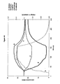
- Figure 5 shows detector signals (interpreted, like Figures 4A and 4B, as the percentage change in signal compared to the clean air value) for a (non-smoke) maize starch dust aerosol (plotted against the right hand axis) compared to obscuration meter values (plotted against the left hand axis).
- Figure 6 shows detector signals (again interpreted, like Figures 4A and 4B, as the percentage change in signal compared to the clean air value) for a water mist aerosol (plotted against the right hand axis) compared to obscuration meter values (plotted against the left hand axis).
- non-smoke aerosols produced somewhat different patterns as compared with the patterns produced for smoke ( Figures 4A and 4B).
- the relationship between the blue and infrared signals, for both the integrating and scattering detectors, in response to non-smoke aerosols is significantly different from that relationship in response to smoke particles. More specifically, the infrared signals are greater, relative to the blue signals, in response to non-smoke particles than is the case in response to smoke particles.
- the integrating detector obscuration values for the infrared signal are, in both cases consistently higher than the blue values even though the values are small.
- the scatter detector signals are almost the same.
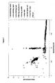
- Figure 7 shows the plot obtained when the ratio of the blue to infrared scatter signals is plotted against the ratio of the blue integrating detector signal to the blue scatter detector signal.
- the signals used in both ratios were the percentage change from the clean air signal. These changes can be positive or negative, depending on whether the absorption or scattering predominates, therefore the ratios can also be positive or negative.
- the white or grey smoke data from smouldering fires are solid shapes
- the black smoke data from flaming fires are hollow shapes
- the non-smoke aerosol data are black or grey crosses or lines.
- the data plotted for the non-smoke aerosols was all the data recorded where either the integrated blue signal or the scatter blue signal had changed by more than 0.5% from the initial, clean air value.
- the same condition was applied except that data was only plotted while the smoke density was increasing. It is clear, from Figure 7, that the aerosols can be classified as black smoke, white smoke or non-smoke, from their position on this plot. Also included in Figure 7 is data recorded while the air temperature inside the smoke box was increased by blowing in hot air. These data points fell within the region occupied by the non-smoke aerosols.
- the signal changes from the blue channel were greater than on the red channel for the scatter detector 9 signals and the integrating detector 5 signals. It was not obvious that it would be the case for the integrating detector signals, where scattering contributes less to the signal. There may be several reasons for this.
- the scattered signal although small, may still be the dominant effect particularly for white smokes where other effects are small.
- the absorption in the blue may be higher than in the infrared or, alternatively, the white coating on the integrating sphere may work better in the blue giving a longer effective absorption path length. It is known, from the obscuration meter data, that the total of the scatter, reflection and absorption losses are higher in the visible than in the infrared region but the absorption component of this cannot be simply determined.
- the apparent path length for absorption in the integrating sphere can be estimated by comparing the measured integrating sphere obscuration with the visible obscuration meter data. If the geometric absorption length is taken as twice the sphere diameter, i.e. 100mm, the apparent absorption length for black smoke is about 150mm for the blue signal and 80mm for the infrared signal. These results may be improved with better coatings on the sphere. However, they are not unreasonable given that the integrating sphere is only sensitive to the absorption contribution to the conventional obscuration reading and the sphere is not complete due to the addition of the scattering detector and smoke access apertures.
- the integrating sphere is a simple way of obtaining an absorption path length that is longer than a double pass across the smoke chamber, with no critical optical alignment. This may provide better discrimination of different smoke types because the integrating sphere is particularly sensitive to absorption.
- the apparent absorption path length may vary with contamination of the sphere surface. However, only absorbing contamination should have a marked effect. Contamination which only scatters light will not have a large effect, unlike its effect on conventional optical systems. It may be advantageous to make the scattering properties of the sphere surface non-optimal, as manufactured, so that there is less change induced by contamination with time.
- the obscurations levels which produce alarms for various smoke particles are listed in the Table below. Also listed in the Table are values for the non-smoke aerosols where the obscuration levels quoted would not be alarms but values where a discrimination decision would be taken.
- the 1% signal change occurred on the scattering detector first.
- the aerosol spray can test the 1% signal change occurred on the integrated blue signal first.
- the values quoted in the Table are from the measured data, and they make no allowance for the fact that the smoke density at the detector lags that at the obscuration meters because of the smoke transit time. The values in the Table are therefore minimum sensitivity values. The smoke transit time has more effect on the black smoke obscurations as the rate of rise of smoke density was greater in these tests.
- Aerosol source type
- Visible obscuration %/m
- Infrared obscuration %/m
- Smouldering cotton white
- %/m Infrared obscuration
- Smouldering cotton white
- %/m Infrared obscuration
- Smouldering cotton white
- %/m Smouldering cotton
- Smouldering paper white
- 0.6 Smouldering card (white)
- Flaming polystyrene black
- Flaming paraffin black
- Aerosol spray can non-smoke
- the data in the Table indicates that the signal change at alarm condition could be relaxed for the standard smouldering cotton test smoke for conventional smoke detector sensitivity while maintaining a sensitive alarm for black smokes to improve the uniformity of response.
- Increasing the white smoke alarm threshold also has the effect of making the sensitivity to the different white smokes more uniform, as some of the variance in the Table is due to differences in the rate of rise of the smoke density. If the smouldering cotton alarm is set at about 6%/m, to match the flaming paraffin sensitivity, then the smouldering paper and smouldering card alarms would occur at 9 and 10%/m respectively.
- the use of the four available signals for alarm generation, and the use of signal ratios provides some compensation for, or recognition of, environmental effects and long term changes in the device, such as caused by contamination of the sphere surface. For instance, the effect of a temperature change is significantly different from that of a smoke aerosol.
- Advantages of the embodiment described include: the enhanced sensitivity to absorption, increasing the discrimination between black and white smoke; the ability to make measurements at two or more wavelengths and use the signal ratios for smoke/non-smoke discrimination; and increased absorption path length with no optical components and critical alignment.
- the data from Figure 7 can be used to set a series of value ranges for "blueint”, “redint”, “bluescatt” and “redscatt” indicative of black smoke from flaming materials and white/grey smoke from smouldering materials.
- the values of "blueint”, “redint”, “bluescatt” and “redscatt” received from the smoke detector 1 can be compared to these ranges by a computer program running on computer 27 (or by any other data processing means, whether implemented by hardware or software) to provide an alarm indicative of black or white/grey smoke being present at the detector 1.
Landscapes
- Physics & Mathematics (AREA)
- General Physics & Mathematics (AREA)
- Chemical & Material Sciences (AREA)
- Analytical Chemistry (AREA)
- Business, Economics & Management (AREA)
- Emergency Management (AREA)
- Biochemistry (AREA)
- Life Sciences & Earth Sciences (AREA)
- Health & Medical Sciences (AREA)
- General Health & Medical Sciences (AREA)
- Immunology (AREA)
- Pathology (AREA)
- Engineering & Computer Science (AREA)
- Computer Security & Cryptography (AREA)
- Fire-Detection Mechanisms (AREA)
- Investigating Or Analysing Materials By Optical Means (AREA)
Claims (36)
- Teilchendetektor, der eine Kammer (2) mit einer im Wesentlichen Lambert'schen Fläche (3) mit im Wesentlichen hoher Reflektivität und zum Aufnehmen von Teilchen, eine Strahlung emittierende Einrichtung (19) zum Emittieren von Strahlung in die Kammer (2) und eine Strahlungsdetektionseinrichtung (5) zum Detektieren der Wirkung der Teilchen auf die Strahlung innerhalb der Kammer (2) enthält,
dadurch gekennzeichnet, dass die Strahlungsdetektionseinrichtung (5) primär zum Detektieren von Absorption der Strahlung durch die Teilchen ist und die Strahlungsdetektionseinrichtung (5) einen breiten Blickwinkel hat, um Strahlung direkt von einem wesentlichen Teil der Lambert'schen Fläche (3) hoher Reflektivität, welche Fläche direkt durch die Strahlung emittierende Einrichtung bestrahlt wird, zu empfangen. - Detektor nach Anspruch 1, wobei die Teilchen Rauchteilchen enthalten.
- Detektor nach Anspruch 1 oder 2, wobei die Lambert'sche Fläche (3) hoher Reflektivität eine Mehrheit der Fläche der Kammer (2) ist.
- Detektor nach Anspruch 1, wobei die Lambert'sche Fläche (3) hoher Reflektivität wenigstens 80% der Fläche der Kammer (2) bedeckt.
- Teilchendetektor nach einem der vorhergehenden Ansprüche, der eine zweite Strahlungsdetektionseinrichtung (9), primär zum Detektieren der Streuung von Strahlung durch die Partikel, enthält.
- Detektor nach einem der vorhergehenden Ansprüche, der eine zweite Strahlung emittierende Einrichtung (21) zum Emittieren von Strahlung in die Kammer (2) enthält, wobei die zweite Strahlung emittierende Einrichtung (21) eine Wellenlänge oder Wellenlängen hat, die von der Wellenlänge oder den Wellenlängen, die durch die erste Strahlung emittierende Einrichtung (19) emittiert wird bzw. werden, verschieden ist bzw. sind.
- Detektor nach Anspruch 6, wobei die erste Strahlung emittierende Einrichtung (19) Blaulicht emittiert und die zweite Strahlung emittierende Einrichtung (21) Infrarotstrahlung emittiert.
- Detektor nach einem der vorhergehenden Ansprüche, wobei die Kammer (2) eine Strahlung absorbierende Fläche (13) enthält.
- Detektor nach Anspruch 8, wobei die Strahlung absorbierende Fläche (13) schwarz ist.
- Detektor nach Anspruch 8 oder 9, wobei die Kammer (2) Löcher (15) enthält, die das Durchlassen von Teilchen ermöglichen, wobei wenigstens eines der Löcher (15) in der Strahlung absorbierenden Fläche (13) ist.
- Detektor nach Anspruch 8, 9 oder 10, wobei die erste Strahlungsdetektionseinrichtung (5) auf der Strahlung absorbierenden Fläche (13) angeordnet ist.
- Detektor nach einem der Ansprüche 8 bis 11, wobei die zweite Strahlungsdetektionseinrichtung (9) im Wesentlichen nur auf Strahlung in einem Weg zwischen der zweiten Strahlungsdetektionseinrichtung (9) und der Strahlung absorbierenden Fläche (13) reagiert.
- Detektor nach Anspruch 6 oder 7, der Einrichtungen (23, 27) zum Verarbeiten von Signalen von der Strahlungsdetektionseinrichtung oder von jeder Strahlungsdetektionseinrichtung (5, 9) enthält, um Daten zu erhalten, die die detektierte Strahlung anzeigen, die durch jede der Strahlung emittierenden Einrichtungen (19, 21) emittiert wurden.
- Detektor nach Anspruch 13, wobei die Daten durch Frequenzmultiplexen erhalten werden.
- Detektor nach Anspruch 13, wobei die Daten durch Zeitmultiplexen erhalten werden.
- Detektor nach Anspruch 13, wobei die zwei Strahlung emittierenden Einrichtungen (19, 21) auf verschiedenen Frequenzen angesteuert werden und die Verarbeitungseinrichtung (23, 25, 27) Lock-in-Verstärker enthält, die auf verschiedenen Frequenzen und zum Empfangen des Ausgangs der Detektionseinrichtungen (5, 9) betriebsfähig sind.
- Detektor nach einem der vorhergehenden Ansprüche, wobei die Strahlung emittierende Einrichtung oder die Strahlung emittierenden Einrichtungen (19, 21) in Bezug auf die Strahlungsdetektionseinrichtung oder jede Strahlungsdetektionseinrichtung (5, 9) beliebig positioniert ist bzw. sind.
- Detektor nach einem der vorhergehenden Ansprüche, wobei die oder jede Strahlung emittierende Einrichtung (19, 21) einen Öffnungswinkel zwischen ungefähr +10° oder -10° und ungefähr +15° oder -15° hat.
- Detektor nach Anspruch 5 und Anspruch 2, eine Verarbeitungseinrichtung (23, 25, 27) zum Analysieren von Daten von den zwei Strahlungsdetektionseinrichtungen (5, 9) enthaltend, um Eigenschaften der Rauchteilchen in der Kammer (2) zu bestimmen.
- Detektor nach Anspruch 5 und Anspruch 2 oder Anspruch 3, eine Verarbeitungseinrichtung (23, 25, 27) zum Analysieren von Daten von den zwei Strahlungsdetektionseinrichtungen (5, 9) enthaltend, um zu bestimmen, ob Rauchteilchen oder andere Teilchen in der Kammer (2) vorhanden sind.
- Detektor nach einem der vorhergehenden Ansprüche, wobei die erste Strahlungsdetektionseinrichtung (9) und die Kammer (2) so konfiguriert sind, dass die erste Strahlungsdetektionseinrichtung (9) einen direkten Blick auf im Wesentlichen die gesamte Kammer (2) hat.
- Detektor nach einem der vorhergehenden Ansprüche, wobei die Kammer (2) ellipsenförmig ist.
- Detektor nach einem der vorhergehenden Ansprüche, wobei die Kammer (2) kugelförmig ist.
- Detektor nach einem der vorhergehenden Ansprüche, wobei die Kammer (2) eine Ulbricht-Kugel (2) ist.
- Detektor nach Anspruch 6 oder 7, die zusätzlich zu der ersten Strahlung emittierenden Einrichtung und der zweiten Strahlung emittierenden Einrichtung (19, 21) wenigstens eine weitere Strahlung emittierende Einrichtung enthält, wobei die weitere Strahlung emittierende Einrichtung eine Wellenlänge oder Wellenlängen hat, die von der Wellenlänge oder den Wellenlängen der ersten Strahlung emittierenden Einrichtung und der zweiten Strahlung emittierenden Einrichtung (19, 21) verschieden ist bzw. sind.
- Teilchendetektor nach einem der vorhergehenden Ansprüche, wobei die Lambert'sche Fläche mehr als 90% der Strahlung reflektiert.
- Teilchendetektionsverfahren, das die folgenden Schritte umfasst: Bereitstellen einer Kammer (2) mit einer im Wesentlichen Lambert'schen Fläche (3) mit im Wesentlichen hoher Reflektivität und zum Aufnehmen von Teilchen, Emittieren von Strahlung in die Kammer (2) und Detektieren der Wirkung der Teilchen auf die Strahlung innerhalb der Kammer (2), dadurch gekennzeichnet, dass der Schritt des Detektierens von Strahlung das Detektieren der Absorption von Strahlung durch Empfangen von Strahlung direkt von einem wesentlichen Teil der Lambert'schen Fläche (3) hoher Reflektivität, welche Fläche durch die Strahlung emittierende Einrichtung direkt bestrahlt wird, enthält.
- Verfahren nach Anspruch 27, wobei die Teilchen Rauchteilchen sind.
- Verfahren nach Anspruch 27 oder 28 wobei der Schritt des Detektierens von Strahlung des Weiteren den Schritt des Detektierens von Streuung von Strahlung umfasst.
- Verfahren nach Anspruch 27, 28 oder 29, wobei der Schritt des Emittierens von Strahlung die Schritte des Emittierens von Strahlung auf zwei verschiedenen Wellenlängen oder Wellenlängenbereichen enthält.
- Verfahren nach Anspruch 30, wobei eine der Wellenlängen oder einer der Wellenlängenbereiche dem des Blaulichts entspricht und die andere der Wellenlängen oder der Wellenlängenbereiche dem der Infrarotstrahlung entspricht.
- Verfahren nach Anspruch 30 oder 31, das den Schritt des Analysierens der detektierten Strahlung enthält, um Daten zu erhalten, die die bei jeder der Wellenlängen oder Wellenlängenbereiche empfangene Strahlung anzeigen.
- Verfahren nach Anspruch 32, das den Schritt des Ableitens von Signalen aus den Daten umfasst, die die Art der Teilchen innerhalb der Kammer anzeigen.
- Verfahren nach Anspruch 33, das den Schritt des Ableitens von Signalen enthält, die anzeigen, ob die Teilchen Rauchteilchen sind oder nicht.
- Verfahren nach Anspruch 30 oder 31, das den Schritt des Emittierens von Strahlung von wenigstens einer weiteren Wellenlänge oder wenigstens eines weiteren Wellenlängenbereichs enthält, die bzw. der verschieden von den zwei Wellenlängen oder Wellenlängenbereichen ist.
- Verfahren nach einem der Ansprüche 27 bis 35, wobei die Lambert'sche Fläche mehr als 90% der Strahlung reflektiert.
Priority Applications (1)
| Application Number | Priority Date | Filing Date | Title |
|---|---|---|---|
| DE60315449T DE60315449T3 (de) | 2002-05-27 | 2003-05-15 | Rauchmelder |
Applications Claiming Priority (3)
| Application Number | Priority Date | Filing Date | Title |
|---|---|---|---|
| GB0212171A GB2389176C (en) | 2002-05-27 | 2002-05-27 | Smoke detector |
| GB0212171 | 2002-05-27 | ||
| PCT/GB2003/002121 WO2003100397A1 (en) | 2002-05-27 | 2003-05-15 | Smoke detector |
Publications (3)
| Publication Number | Publication Date |
|---|---|
| EP1508032A1 EP1508032A1 (de) | 2005-02-23 |
| EP1508032B1 true EP1508032B1 (de) | 2007-08-08 |
| EP1508032B3 EP1508032B3 (de) | 2010-03-31 |
Family
ID=9937487
Family Applications (1)
| Application Number | Title | Priority Date | Filing Date |
|---|---|---|---|
| EP03725408A Expired - Lifetime EP1508032B3 (de) | 2002-05-27 | 2003-05-15 | Rauchmelder |
Country Status (7)
| Country | Link |
|---|---|
| US (1) | US7483139B2 (de) |
| EP (1) | EP1508032B3 (de) |
| AT (1) | ATE369554T1 (de) |
| AU (1) | AU2003227943A1 (de) |
| DE (1) | DE60315449T3 (de) |
| GB (1) | GB2389176C (de) |
| WO (1) | WO2003100397A1 (de) |
Cited By (1)
| Publication number | Priority date | Publication date | Assignee | Title |
|---|---|---|---|---|
| US7483139B2 (en) | 2002-05-27 | 2009-01-27 | Kidde Ip Holdings Limited | Smoke detector |
Families Citing this family (54)
| Publication number | Priority date | Publication date | Assignee | Title |
|---|---|---|---|---|
| US7233253B2 (en) | 2003-09-12 | 2007-06-19 | Simplexgrinnell Lp | Multiwavelength smoke detector using white light LED |
| AU2004201100B2 (en) * | 2004-03-16 | 2009-11-12 | Novar Gmbh | Fire Detection Method and Fire Detector Therefor |
| EP1810259A1 (de) * | 2004-10-29 | 2007-07-25 | Simplexgrinnell Lp | Mehrwellenlängen-rauchdetektor mit weisslicht-led |
| GB2423357A (en) * | 2005-02-22 | 2006-08-23 | Thorn Security | A self-monitoring smoke detector |
| CA2867838C (en) * | 2005-12-14 | 2016-08-02 | Stryker Corporation | Medical surgical waste collection and disposal system including a rover and a docker, the docker having features facilitating the alignment of the docker with the rover |
| US7615037B2 (en) | 2005-12-14 | 2009-11-10 | Stryker Corporation | Removable inlet manifold for a medical/surgical waste collection system, the manifold including a driver for actuating a valve integral with the waste collection system |
| US7528951B2 (en) * | 2006-03-23 | 2009-05-05 | Hach Company | Optical design of a measurement system having multiple sensor or multiple light source paths |
| EP2135057A4 (de) * | 2007-03-09 | 2010-03-24 | Xtralis Technologies Ltd | Verfahren und system zum partikelnachweis |
| DE102007045018B4 (de) | 2007-09-20 | 2011-02-17 | Perkinelmer Optoelectronics Gmbh & Co.Kg | Strahlungsleitvorrichtung für einen Detektor, Streustrahlungsdetektor |
| US8085157B2 (en) * | 2007-10-24 | 2011-12-27 | Honeywell International Inc. | Smoke detectors |
| JP2009122983A (ja) * | 2007-11-15 | 2009-06-04 | Sharp Corp | 煙センサおよび電子機器 |
| US8111168B2 (en) * | 2009-04-02 | 2012-02-07 | Kidde Technologies, Inc. | Smoke detector with included flame barrier |
| DE102009031099A1 (de) * | 2009-06-29 | 2010-12-30 | Ista International Gmbh | Rauchwarnmelder und Verfahren zur Überprüfung der Verschmutzung der Rauchdurchtrittsöffnungen |
| US8785874B2 (en) | 2010-12-30 | 2014-07-22 | Walter Kidde Portable Equipment, Inc. | Ionization window |
| US9053892B2 (en) | 2010-12-30 | 2015-06-09 | Walter Kidde Portable Equipment, Inc. | Ionization device |
| CN103597525B (zh) * | 2011-08-29 | 2015-09-30 | 日本芬翁股份有限公司 | 光电式烟感测器 |
| JP6029055B2 (ja) * | 2011-10-24 | 2016-11-24 | パナソニックIpマネジメント株式会社 | 煙感知器 |
| US20130126508A1 (en) * | 2011-11-17 | 2013-05-23 | Texas Instruments Incorporated | Extending Radiation Tolerance By Localized Temperature Annealing Of Semiconductor Devices |
| US8907802B2 (en) | 2012-04-29 | 2014-12-09 | Valor Fire Safety, Llc | Smoke detector with external sampling volume and ambient light rejection |
| US9140646B2 (en) | 2012-04-29 | 2015-09-22 | Valor Fire Safety, Llc | Smoke detector with external sampling volume using two different wavelengths and ambient light detection for measurement correction |
| US8952821B2 (en) | 2012-04-29 | 2015-02-10 | Valor Fire Safety, Llc | Smoke detector utilizing ambient-light sensor, external sampling volume, and internally reflected light |
| US8743366B2 (en) * | 2012-08-31 | 2014-06-03 | Fenwal Controls Of Japan, Ltd. | Light emission portion, photoelectric smoke sensor, and suction-type smoke sensing system |
| KR20160079057A (ko) | 2013-10-30 | 2016-07-05 | 발로르 파이어 세이프티, 엘엘씨 | 외부 샘플링 볼륨 및 주변광 배제를 갖는 연기 감지기 |
| US9679468B2 (en) | 2014-04-21 | 2017-06-13 | Tyco Fire & Security Gmbh | Device and apparatus for self-testing smoke detector baffle system |
| US9659485B2 (en) | 2014-04-23 | 2017-05-23 | Tyco Fire & Security Gmbh | Self-testing smoke detector with integrated smoke source |
| US9552711B2 (en) | 2014-07-18 | 2017-01-24 | Google Inc. | Systems and methods for intelligent alarming |
| US9196141B1 (en) * | 2015-05-15 | 2015-11-24 | Google, Inc. | Smoke detector chamber |
| MX389745B (es) | 2016-06-15 | 2025-03-20 | Carrier Corp | Metodología de detección de humo. |
| WO2018027104A1 (en) * | 2016-08-04 | 2018-02-08 | Carrier Corporation | Smoke detector |
| DE102016120785A1 (de) * | 2016-11-01 | 2018-05-03 | Krohne Messtechnik Gmbh | Verfahren und Messgerät zur Bestimmung einer Eigenschaft eines Mediums |
| US10339794B2 (en) | 2017-01-26 | 2019-07-02 | Google Llc | Smoke detector and method for determining failure thereof |
| CN107016816B (zh) * | 2017-05-12 | 2020-08-14 | 浙江恒洲电子实业有限公司 | 烟雾探测器迷宫结构及其烟雾探测方法 |
| US10102728B1 (en) * | 2017-06-14 | 2018-10-16 | Google Llc | Smoke detector for event classification and methods of making and using same |
| RU179257U1 (ru) * | 2017-07-03 | 2018-05-07 | федеральное государственное автономное образовательное учреждение высшего образования "Санкт-Петербургский национальный исследовательский университет информационных технологий, механики и оптики" (Университет ИТМО) | Оптический датчик дыма |
| US10809173B2 (en) * | 2017-12-15 | 2020-10-20 | Analog Devices, Inc. | Smoke detector chamber boundary surfaces |
| US11788942B2 (en) | 2017-12-15 | 2023-10-17 | Analog Devices, Inc. | Compact optical smoke detector system and apparatus |
| US11783688B2 (en) * | 2018-03-13 | 2023-10-10 | Carrier Corporation | Aspirating detector system |
| CN116275467A (zh) * | 2018-06-05 | 2023-06-23 | 伊雷克托科学工业股份有限公司 | 激光加工设备、其操作方法以及使用其加工工件的方法 |
| US12211370B2 (en) | 2018-12-02 | 2025-01-28 | Analog Devices, Inc. | Fire detection system |
| EP3951733A4 (de) * | 2019-03-29 | 2023-01-25 | Hochiki Corporation | Brandmeldeanlage |
| US11318242B2 (en) | 2019-04-12 | 2022-05-03 | Stryker Corporation | Manifold for a medical waste collection system |
| US12350418B2 (en) | 2019-04-12 | 2025-07-08 | Stryker Corporation | Manifold for a medical waste collection system |
| US10471188B1 (en) | 2019-04-12 | 2019-11-12 | Stryker Corporation | Manifold for filtering medical waste being drawn under vacuum into a medical waste collection system |
| US11796445B2 (en) | 2019-05-15 | 2023-10-24 | Analog Devices, Inc. | Optical improvements to compact smoke detectors, systems and apparatus |
| CN110136390A (zh) * | 2019-05-28 | 2019-08-16 | 赛特威尔电子股份有限公司 | 一种烟雾检测方法、装置、烟雾报警器及存储介质 |
| JP7336344B2 (ja) * | 2019-09-30 | 2023-08-31 | ニッタン株式会社 | 煙感知器および煙感知システム |
| USD919799S1 (en) | 2019-11-11 | 2021-05-18 | Stryker Corporation | Manifold housing for a medical waste collection device |
| USD956967S1 (en) | 2019-11-11 | 2022-07-05 | Stryker Corporation | Manifold housing for a medical waste collection device |
| USD930850S1 (en) | 2019-11-20 | 2021-09-14 | Stryker Corporation | Specimen collection tray |
| USD996640S1 (en) | 2019-11-11 | 2023-08-22 | Stryker Corporation | Specimen collection tray |
| USD1031076S1 (en) | 2019-11-20 | 2024-06-11 | Stryker Corporation | Specimen collection tray |
| CN112683806B (zh) * | 2020-12-08 | 2022-09-02 | 大连理工大学 | 一种利用醋酸纤维膜实现光声系统灵敏度增强和光声池免抛光的方法 |
| CN113820259B (zh) * | 2021-09-22 | 2024-12-24 | 深圳市高新投三江电子股份有限公司 | 一种感烟探测器灰尘响应性能的测试装置 |
| US11790765B1 (en) * | 2022-08-01 | 2023-10-17 | Honeywell International Inc. | Smoke detector device with secondary detection chamber and filter |
Family Cites Families (25)
| Publication number | Priority date | Publication date | Assignee | Title |
|---|---|---|---|---|
| FR2175395A5 (de) * | 1972-01-28 | 1973-10-19 | Sartorius Membranfilter Gmbh | |
| CH561942A5 (de) * | 1974-03-08 | 1975-05-15 | Cerberus Ag | |
| CH607687A5 (en) * | 1977-02-18 | 1978-10-13 | Cerberus Ag | Scattered radiation smoke detector |
| US4221485A (en) * | 1979-06-04 | 1980-09-09 | Honeywell Inc. | Optical smoke detector |
| ATE24787T1 (de) * | 1980-12-18 | 1987-01-15 | Cerberus Ag | Rauchmelder nach dem strahlungs-extinktionsprinzip. |
| GB2141553B (en) * | 1983-06-14 | 1987-06-03 | Standard Telephones Cables Ltd | Scatter cells for photo sensors |
| US4711571A (en) * | 1986-01-15 | 1987-12-08 | Mark Schuman | Radiant emission and absorption multigas analyzer |
| US4857895A (en) * | 1987-08-31 | 1989-08-15 | Kaprelian Edward K | Combined scatter and light obscuration smoke detector |
| US5392114A (en) * | 1988-03-30 | 1995-02-21 | Cole; Martin T. | Fluid pollution monitor |
| US4942305A (en) * | 1989-05-12 | 1990-07-17 | Pacific Scientific Company | Integrating sphere aerosol particle detector |
| US5220179A (en) * | 1990-02-06 | 1993-06-15 | Helmut Katschnig | Method of and apparatus for detecting the presence of vapor and/or smoke in the outgoing air of a device for heating materials |
| CH683464A5 (de) * | 1991-09-06 | 1994-03-15 | Cerberus Ag | Optischer Rauchmelder mit aktiver Ueberwachung. |
| US6501810B1 (en) * | 1998-10-13 | 2002-12-31 | Agere Systems Inc. | Fast frame synchronization |
| US5491336A (en) * | 1993-12-22 | 1996-02-13 | Unisys Corporation | Document illumination with Lambertian cavity |
| DE19610438C2 (de) * | 1995-04-28 | 1998-11-26 | Deutsch Zentr Luft & Raumfahrt | Verfahren und Vorrichtung zur Bestimmung der Lichtabsorption eines beliebig geformten Partikels |
| GB2319604A (en) * | 1996-11-25 | 1998-05-27 | Kidde Fire Protection Ltd | Smoke and particle detector |
| GB9721861D0 (en) | 1997-10-15 | 1997-12-17 | Kidde Fire Protection Ltd | High sensitivity particle detection |
| US7023913B1 (en) * | 2000-06-14 | 2006-04-04 | Monroe David A | Digital security multimedia sensor |
| JP2000206035A (ja) * | 1999-01-19 | 2000-07-28 | Anritsu Corp | ガス検出装置 |
| JP4061765B2 (ja) * | 1999-02-09 | 2008-03-19 | コニカミノルタセンシング株式会社 | 蛍光試料の分光特性測定装置及びその測定方法 |
| US6225910B1 (en) * | 1999-12-08 | 2001-05-01 | Gentex Corporation | Smoke detector |
| US6788211B2 (en) * | 2000-06-14 | 2004-09-07 | Edwards Systems Technology, Inc. | Apparatus and method using smoke and/or gas sensing in cooking devices |
| US6469623B2 (en) * | 2001-01-26 | 2002-10-22 | Gentex Corporation | Smoke detector maintenance and verification tool |
| GB2389176C (en) | 2002-05-27 | 2011-07-27 | Kidde Ip Holdings Ltd | Smoke detector |
| US7048068B2 (en) * | 2003-07-23 | 2006-05-23 | Paulkovich Michael B | Fire extinguishing system for large structures |
-
2002
- 2002-05-27 GB GB0212171A patent/GB2389176C/en not_active Expired - Fee Related
-
2003
- 2003-05-15 EP EP03725408A patent/EP1508032B3/de not_active Expired - Lifetime
- 2003-05-15 US US10/515,883 patent/US7483139B2/en not_active Expired - Lifetime
- 2003-05-15 WO PCT/GB2003/002121 patent/WO2003100397A1/en not_active Ceased
- 2003-05-15 DE DE60315449T patent/DE60315449T3/de not_active Expired - Lifetime
- 2003-05-15 AU AU2003227943A patent/AU2003227943A1/en not_active Abandoned
- 2003-05-15 AT AT03725408T patent/ATE369554T1/de not_active IP Right Cessation
Cited By (1)
| Publication number | Priority date | Publication date | Assignee | Title |
|---|---|---|---|---|
| US7483139B2 (en) | 2002-05-27 | 2009-01-27 | Kidde Ip Holdings Limited | Smoke detector |
Also Published As
| Publication number | Publication date |
|---|---|
| GB2389176C (en) | 2011-07-27 |
| ATE369554T1 (de) | 2007-08-15 |
| GB2389176B (en) | 2005-10-12 |
| GB2389176A (en) | 2003-12-03 |
| DE60315449D1 (de) | 2010-10-14 |
| US20050173638A1 (en) | 2005-08-11 |
| DE60315449T3 (de) | 2012-01-12 |
| WO2003100397A1 (en) | 2003-12-04 |
| GB0212171D0 (en) | 2002-07-03 |
| DE60315449T2 (de) | 2008-04-30 |
| AU2003227943A1 (en) | 2003-12-12 |
| EP1508032A1 (de) | 2005-02-23 |
| EP1508032B3 (de) | 2010-03-31 |
| US7483139B2 (en) | 2009-01-27 |
Similar Documents
| Publication | Publication Date | Title |
|---|---|---|
| EP1508032B1 (de) | Rauchmelder | |
| CN108205867B (zh) | 一种具备干扰粒子识别能力的早期火灾烟雾探测方法 | |
| CN103782327B (zh) | 用于检测散射光信号的设备和方法 | |
| US7724367B2 (en) | Particle monitors and method(s) therefor | |
| US7292338B2 (en) | Particle detection apparatus and particle detection method used therefor | |
| EP2112639B1 (de) | Verbesserung(en) in Zusammenhang mit Teilchendetektoren | |
| US6479833B1 (en) | Fire alarm box with direct and scattered light detection and gas-sensitive layers | |
| EP1261953A1 (de) | Verbesserungen für rauchdetektoren, insbesondere rauchdetektoren mit kanal | |
| AU2001231426A1 (en) | Improvements relating to smoke detectors particularly ducted smoke detectors | |
| GB2397122A (en) | Smoke detector with a low false alarm rate | |
| US7167098B2 (en) | Testing equipment for a fire alarm | |
| GB2319604A (en) | Smoke and particle detector | |
| CN209248721U (zh) | 迷宫式光学探测器 | |
| US20030201899A1 (en) | Signaling fire detector | |
| US12223815B2 (en) | Smoke detection device, a scattered light sensor of the smoke detection device, and a method for detecting a smoke by means of the device | |
| CN119007378B (zh) | 基于颗粒粒径、形状及折射率联合特征的火灾烟雾探测器 | |
| JPH04233100A (ja) | 光学式火災報知器 | |
| JPH04205400A (ja) | 煙感知器 | |
| CN215833209U (zh) | 一种双波长气溶胶粒子散射光传感结构 | |
| AU2007203110A1 (en) | Improvement(s) related to particle monitors and method(s) therefor | |
| Long et al. | Analysis of the impact of multi-wavelength light scattering on the detection of the Sauter mean diameter of fire smoke particles | |
| JPH11339157A (ja) | 煙感知装置 | |
| CA2598926A1 (en) | Improvement(s) related to particle monitors and method(s) therefor | |
| SU1661816A1 (ru) | Способ обнаружени возгораний и устройство дл его осуществлени | |
| HU227010B1 (hu) | Eljárás tûz észleléséhez, valamint szórtfény elven mûködõ tûzjelzõ |
Legal Events
| Date | Code | Title | Description |
|---|---|---|---|
| PUAI | Public reference made under article 153(3) epc to a published international application that has entered the european phase |
Free format text: ORIGINAL CODE: 0009012 |
|
| 17P | Request for examination filed |
Effective date: 20040907 |
|
| AK | Designated contracting states |
Kind code of ref document: A1 Designated state(s): AT BE BG CH CY CZ DE DK EE ES FI FR GB GR HU IE IT LI LU MC NL PT RO SE SI SK TR |
|
| AX | Request for extension of the european patent |
Extension state: AL LT LV MK |
|
| DAX | Request for extension of the european patent (deleted) | ||
| RBV | Designated contracting states (corrected) |
Designated state(s): AT BE BG CH CY CZ DE DK EE ES FI FR GR HU IE IT LI LU MC NL PT RO SE SI SK TR |
|
| GRAP | Despatch of communication of intention to grant a patent |
Free format text: ORIGINAL CODE: EPIDOSNIGR1 |
|
| GRAS | Grant fee paid |
Free format text: ORIGINAL CODE: EPIDOSNIGR3 |
|
| GRAA | (expected) grant |
Free format text: ORIGINAL CODE: 0009210 |
|
| AK | Designated contracting states |
Kind code of ref document: B1 Designated state(s): AT BE BG CH CY CZ DE DK EE ES FI FR GR HU IE IT LI LU MC NL PT RO SE SI SK TR |
|
| REG | Reference to a national code |
Ref country code: CH Ref legal event code: EP |
|
| REG | Reference to a national code |
Ref country code: IE Ref legal event code: FG4D |
|
| REF | Corresponds to: |
Ref document number: 60315449 Country of ref document: DE Date of ref document: 20070920 Kind code of ref document: P |
|
| ET | Fr: translation filed | ||
| PG25 | Lapsed in a contracting state [announced via postgrant information from national office to epo] |
Ref country code: BG Free format text: LAPSE BECAUSE OF FAILURE TO SUBMIT A TRANSLATION OF THE DESCRIPTION OR TO PAY THE FEE WITHIN THE PRESCRIBED TIME-LIMIT Effective date: 20071108 Ref country code: ES Free format text: LAPSE BECAUSE OF FAILURE TO SUBMIT A TRANSLATION OF THE DESCRIPTION OR TO PAY THE FEE WITHIN THE PRESCRIBED TIME-LIMIT Effective date: 20071119 Ref country code: NL Free format text: LAPSE BECAUSE OF FAILURE TO SUBMIT A TRANSLATION OF THE DESCRIPTION OR TO PAY THE FEE WITHIN THE PRESCRIBED TIME-LIMIT Effective date: 20070808 Ref country code: FI Free format text: LAPSE BECAUSE OF FAILURE TO SUBMIT A TRANSLATION OF THE DESCRIPTION OR TO PAY THE FEE WITHIN THE PRESCRIBED TIME-LIMIT Effective date: 20070808 |
|
| NLV1 | Nl: lapsed or annulled due to failure to fulfill the requirements of art. 29p and 29m of the patents act | ||
| REG | Reference to a national code |
Ref country code: CH Ref legal event code: PL |
|
| PG25 | Lapsed in a contracting state [announced via postgrant information from national office to epo] |
Ref country code: CH Free format text: LAPSE BECAUSE OF FAILURE TO SUBMIT A TRANSLATION OF THE DESCRIPTION OR TO PAY THE FEE WITHIN THE PRESCRIBED TIME-LIMIT Effective date: 20070808 Ref country code: AT Free format text: LAPSE BECAUSE OF FAILURE TO SUBMIT A TRANSLATION OF THE DESCRIPTION OR TO PAY THE FEE WITHIN THE PRESCRIBED TIME-LIMIT Effective date: 20070808 Ref country code: LI Free format text: LAPSE BECAUSE OF FAILURE TO SUBMIT A TRANSLATION OF THE DESCRIPTION OR TO PAY THE FEE WITHIN THE PRESCRIBED TIME-LIMIT Effective date: 20070808 |
|
| PG25 | Lapsed in a contracting state [announced via postgrant information from national office to epo] |
Ref country code: BE Free format text: LAPSE BECAUSE OF FAILURE TO SUBMIT A TRANSLATION OF THE DESCRIPTION OR TO PAY THE FEE WITHIN THE PRESCRIBED TIME-LIMIT Effective date: 20070808 |
|
| PG25 | Lapsed in a contracting state [announced via postgrant information from national office to epo] |
Ref country code: DK Free format text: LAPSE BECAUSE OF FAILURE TO SUBMIT A TRANSLATION OF THE DESCRIPTION OR TO PAY THE FEE WITHIN THE PRESCRIBED TIME-LIMIT Effective date: 20070808 Ref country code: GR Free format text: LAPSE BECAUSE OF FAILURE TO SUBMIT A TRANSLATION OF THE DESCRIPTION OR TO PAY THE FEE WITHIN THE PRESCRIBED TIME-LIMIT Effective date: 20071109 |
|
| PG25 | Lapsed in a contracting state [announced via postgrant information from national office to epo] |
Ref country code: PT Free format text: LAPSE BECAUSE OF FAILURE TO SUBMIT A TRANSLATION OF THE DESCRIPTION OR TO PAY THE FEE WITHIN THE PRESCRIBED TIME-LIMIT Effective date: 20080108 Ref country code: CZ Free format text: LAPSE BECAUSE OF FAILURE TO SUBMIT A TRANSLATION OF THE DESCRIPTION OR TO PAY THE FEE WITHIN THE PRESCRIBED TIME-LIMIT Effective date: 20070808 Ref country code: SK Free format text: LAPSE BECAUSE OF FAILURE TO SUBMIT A TRANSLATION OF THE DESCRIPTION OR TO PAY THE FEE WITHIN THE PRESCRIBED TIME-LIMIT Effective date: 20070808 |
|
| PLBE | No opposition filed within time limit |
Free format text: ORIGINAL CODE: 0009261 |
|
| PG25 | Lapsed in a contracting state [announced via postgrant information from national office to epo] |
Ref country code: SE Free format text: LAPSE BECAUSE OF FAILURE TO SUBMIT A TRANSLATION OF THE DESCRIPTION OR TO PAY THE FEE WITHIN THE PRESCRIBED TIME-LIMIT Effective date: 20071108 Ref country code: RO Free format text: LAPSE BECAUSE OF FAILURE TO SUBMIT A TRANSLATION OF THE DESCRIPTION OR TO PAY THE FEE WITHIN THE PRESCRIBED TIME-LIMIT Effective date: 20070808 |
|
| 26N | No opposition filed |
Effective date: 20080509 |
|
| PG25 | Lapsed in a contracting state [announced via postgrant information from national office to epo] |
Ref country code: MC Free format text: LAPSE BECAUSE OF NON-PAYMENT OF DUE FEES Effective date: 20080531 |
|
| PG25 | Lapsed in a contracting state [announced via postgrant information from national office to epo] |
Ref country code: EE Free format text: LAPSE BECAUSE OF FAILURE TO SUBMIT A TRANSLATION OF THE DESCRIPTION OR TO PAY THE FEE WITHIN THE PRESCRIBED TIME-LIMIT Effective date: 20070808 |
|
| PLCP | Request for limitation filed |
Free format text: ORIGINAL CODE: EPIDOSNLIM1 |
|
| PG25 | Lapsed in a contracting state [announced via postgrant information from national office to epo] |
Ref country code: IE Free format text: LAPSE BECAUSE OF NON-PAYMENT OF DUE FEES Effective date: 20080515 |
|
| PLCQ | Request for limitation of patent found admissible |
Free format text: ORIGINAL CODE: 0009231 |
|
| PG25 | Lapsed in a contracting state [announced via postgrant information from national office to epo] |
Ref country code: SI Free format text: LAPSE BECAUSE OF FAILURE TO SUBMIT A TRANSLATION OF THE DESCRIPTION OR TO PAY THE FEE WITHIN THE PRESCRIBED TIME-LIMIT Effective date: 20070808 |
|
| LIM1 | Request for limitation found admissible |
Free format text: SEQUENCE NO: 1; FILED AFTER OPPOSITION PERIOD Filing date: 20090409 |
|
| PG25 | Lapsed in a contracting state [announced via postgrant information from national office to epo] |
Ref country code: CY Free format text: LAPSE BECAUSE OF FAILURE TO SUBMIT A TRANSLATION OF THE DESCRIPTION OR TO PAY THE FEE WITHIN THE PRESCRIBED TIME-LIMIT Effective date: 20070808 |
|
| PLCO | Limitation procedure: reply received to communication from examining division + time limit |
Free format text: ORIGINAL CODE: EPIDOSNLIR3 |
|
| PLCR | Communication despatched that request for limitation of patent was allowed |
Free format text: ORIGINAL CODE: 0009245 |
|
| PLCN | Payment of fee for limitation of patent |
Free format text: ORIGINAL CODE: EPIDOSNRAL3 |
|
| PUAM | (expected) publication of b3 document |
Free format text: ORIGINAL CODE: 0009410 |
|
| STAA | Information on the status of an ep patent application or granted ep patent |
Free format text: STATUS: THE PATENT HAS BEEN LIMITED |
|
| REG | Reference to a national code |
Ref country code: DE Ref legal event code: 8505 |
|
| REG | Reference to a national code |
Ref country code: CH Ref legal event code: AEN Free format text: BESCHRAENKUNGANTRAG GUTGEHEISSEN |
|
| PG25 | Lapsed in a contracting state [announced via postgrant information from national office to epo] |
Ref country code: LU Free format text: LAPSE BECAUSE OF NON-PAYMENT OF DUE FEES Effective date: 20080515 Ref country code: HU Free format text: LAPSE BECAUSE OF FAILURE TO SUBMIT A TRANSLATION OF THE DESCRIPTION OR TO PAY THE FEE WITHIN THE PRESCRIBED TIME-LIMIT Effective date: 20080209 |
|
| PG25 | Lapsed in a contracting state [announced via postgrant information from national office to epo] |
Ref country code: TR Free format text: LAPSE BECAUSE OF FAILURE TO SUBMIT A TRANSLATION OF THE DESCRIPTION OR TO PAY THE FEE WITHIN THE PRESCRIBED TIME-LIMIT Effective date: 20070808 |
|
| REG | Reference to a national code |
Ref country code: DE Ref legal event code: 8505 |
|
| PG25 | Lapsed in a contracting state [announced via postgrant information from national office to epo] |
Ref country code: IT Free format text: LAPSE BECAUSE OF NON-PAYMENT OF DUE FEES Effective date: 20080531 |
|
| PG25 | Lapsed in a contracting state [announced via postgrant information from national office to epo] |
Ref country code: DE Free format text: LAPSE BECAUSE OF FAILURE TO SUBMIT A TRANSLATION OF THE DESCRIPTION OR TO PAY THE FEE WITHIN THE PRESCRIBED TIME-LIMIT Effective date: 20100701 |
|
| REG | Reference to a national code |
Ref country code: DE Ref legal event code: R119 Ref document number: 60315449 Country of ref document: DE |
|
| PGFP | Annual fee paid to national office [announced via postgrant information from national office to epo] |
Ref country code: DE Payment date: 20140507 Year of fee payment: 12 |
|
| REG | Reference to a national code |
Ref country code: DE Ref legal event code: R119 Ref document number: 60315449 Country of ref document: DE Effective date: 20111201 |
|
| REG | Reference to a national code |
Ref country code: FR Ref legal event code: PLFP Year of fee payment: 13 |
|
| PG25 | Lapsed in a contracting state [announced via postgrant information from national office to epo] |
Ref country code: DE Free format text: LAPSE BECAUSE OF NON-PAYMENT OF DUE FEES Effective date: 20111201 |
|
| PGFP | Annual fee paid to national office [announced via postgrant information from national office to epo] |
Ref country code: FR Payment date: 20150422 Year of fee payment: 13 |
|
| REG | Reference to a national code |
Ref country code: FR Ref legal event code: ST Effective date: 20170131 |
|
| PG25 | Lapsed in a contracting state [announced via postgrant information from national office to epo] |
Ref country code: FR Free format text: LAPSE BECAUSE OF NON-PAYMENT OF DUE FEES Effective date: 20160531 |