EP1508049B1 - Procede et systeme pour determiner la vitesse de rotation par hysteresis de commutation - Google Patents
Procede et systeme pour determiner la vitesse de rotation par hysteresis de commutation Download PDFInfo
- Publication number
- EP1508049B1 EP1508049B1 EP03720222.3A EP03720222A EP1508049B1 EP 1508049 B1 EP1508049 B1 EP 1508049B1 EP 03720222 A EP03720222 A EP 03720222A EP 1508049 B1 EP1508049 B1 EP 1508049B1
- Authority
- EP
- European Patent Office
- Prior art keywords
- hysteresis
- switching
- sensor
- sensor arrangement
- signal
- Prior art date
- Legal status (The legal status is an assumption and is not a legal conclusion. Google has not performed a legal analysis and makes no representation as to the accuracy of the status listed.)
- Expired - Lifetime
Links
- 238000000034 method Methods 0.000 title claims description 11
- 238000011156 evaluation Methods 0.000 claims description 6
- 238000001514 detection method Methods 0.000 description 7
- 230000001419 dependent effect Effects 0.000 description 5
- 238000010586 diagram Methods 0.000 description 5
- 230000036039 immunity Effects 0.000 description 4
- 230000008878 coupling Effects 0.000 description 3
- 238000010168 coupling process Methods 0.000 description 3
- 238000005859 coupling reaction Methods 0.000 description 3
- 238000005259 measurement Methods 0.000 description 3
- 230000003044 adaptive effect Effects 0.000 description 2
- 230000005284 excitation Effects 0.000 description 2
- 230000009467 reduction Effects 0.000 description 2
- 230000035945 sensitivity Effects 0.000 description 2
- 238000012360 testing method Methods 0.000 description 2
- 230000004913 activation Effects 0.000 description 1
- 230000000712 assembly Effects 0.000 description 1
- 238000000429 assembly Methods 0.000 description 1
- 230000005540 biological transmission Effects 0.000 description 1
- 230000008859 change Effects 0.000 description 1
- 230000003750 conditioning effect Effects 0.000 description 1
- 238000011161 development Methods 0.000 description 1
- 230000007774 longterm Effects 0.000 description 1
- 238000012545 processing Methods 0.000 description 1
- 230000004044 response Effects 0.000 description 1
- 230000035939 shock Effects 0.000 description 1
- 230000000638 stimulation Effects 0.000 description 1
Images

Classifications
-
- G—PHYSICS
- G01—MEASURING; TESTING
- G01P—MEASURING LINEAR OR ANGULAR SPEED, ACCELERATION, DECELERATION, OR SHOCK; INDICATING PRESENCE, ABSENCE, OR DIRECTION, OF MOVEMENT
- G01P3/00—Measuring linear or angular speed; Measuring differences of linear or angular speeds
- G01P3/42—Devices characterised by the use of electric or magnetic means
- G01P3/44—Devices characterised by the use of electric or magnetic means for measuring angular speed
- G01P3/48—Devices characterised by the use of electric or magnetic means for measuring angular speed by measuring frequency of generated current or voltage
- G01P3/481—Devices characterised by the use of electric or magnetic means for measuring angular speed by measuring frequency of generated current or voltage of pulse signals
- G01P3/489—Digital circuits therefor
-
- G—PHYSICS
- G01—MEASURING; TESTING
- G01P—MEASURING LINEAR OR ANGULAR SPEED, ACCELERATION, DECELERATION, OR SHOCK; INDICATING PRESENCE, ABSENCE, OR DIRECTION, OF MOVEMENT
- G01P3/00—Measuring linear or angular speed; Measuring differences of linear or angular speeds
- G01P3/42—Devices characterised by the use of electric or magnetic means
- G01P3/44—Devices characterised by the use of electric or magnetic means for measuring angular speed
- G01P3/48—Devices characterised by the use of electric or magnetic means for measuring angular speed by measuring frequency of generated current or voltage
- G01P3/481—Devices characterised by the use of electric or magnetic means for measuring angular speed by measuring frequency of generated current or voltage of pulse signals
-
- G—PHYSICS
- G01—MEASURING; TESTING
- G01P—MEASURING LINEAR OR ANGULAR SPEED, ACCELERATION, DECELERATION, OR SHOCK; INDICATING PRESENCE, ABSENCE, OR DIRECTION, OF MOVEMENT
- G01P3/00—Measuring linear or angular speed; Measuring differences of linear or angular speeds
- G01P3/42—Devices characterised by the use of electric or magnetic means
- G01P3/44—Devices characterised by the use of electric or magnetic means for measuring angular speed
- G01P3/48—Devices characterised by the use of electric or magnetic means for measuring angular speed by measuring frequency of generated current or voltage
- G01P3/481—Devices characterised by the use of electric or magnetic means for measuring angular speed by measuring frequency of generated current or voltage of pulse signals
- G01P3/487—Devices characterised by the use of electric or magnetic means for measuring angular speed by measuring frequency of generated current or voltage of pulse signals delivered by rotating magnets
Definitions
- the invention relates to a method and an arrangement for detecting the movement of an element relative to a sensor arrangement, in particular for detecting the angle of rotation of a rotating element, according to the preamble of the main claim.
- Such sensor arrangements are already used in different embodiments, for example in vehicles.
- Hall elements as a speed sensor on the wheels for an anti-lock braking system (ABS), as speed and phase encoder for the engine control or steering angle sensors for so-called.
- Vehicle dynamics control systems and electric power steering usually give digital signals, eg. B. switching edges, in response to a rotating sensor in front of the sensor wheel.
- variable hysteresis is often used in conventional speed sensors.
- the signal amplitude must be measured and then the hysteresis is flexibly adjusted.
- a large hysteresis and for small input signals a correspondingly reduced hysteresis is selected, ie, it is increased at a small air gap, the amplitude necessary for switching.
- the transmitter wheel is at a standstill, there is a demand for immunity of the sensor against vibrations, which initially precludes high sensitivity and necessitates the realization of a large switching hysteresis.
- the realized sensor is insensitive to short-term signal changes, in particular a significant reduction in amplitude during operation. Therefore, a major disadvantage of this method with a flexible hysteresis is the loss of immunity, especially against air-gap impacts during operation, which can briefly produce such a significant reduction in signal amplitude. Due to a previously increased hysteresis in the switching point of the sensor, it may then come with such an air gap impact possibly to loss of signal or a signal rupture.
- the method with an adaptive hysteresis can only be used after calibration of the sensor, since the signal amplitude is known only after the calibration.
- the sensor would first have to measure the signal amplitude. Since there are no measured values directly after switching on, a start value, usually the minimum, must be selected for the hysteresis in the sensor. At the same time, however, this means that the sensor is very susceptible to vibration in this condition.
- the senor loses its robustness due to increased hysteresis during magnetic stimulation (ie, while the transmitter wheel is rotating) Air gap blows that can drastically reduce the signal amplitude over a few periods.
- the EP 1 111 392 A1 describes a non-contact speed sensor are detected in the sample marks of a wheel, with switching thresholds for the downstream sensor arrangement are also present here with respect to the sampled pulses. These switching thresholds are adjusted via a control arrangement such that an offset or a long-term drift of the sensor can be compensated.
- the invention relates to a development of a method for detecting the movement of an element relative to a sensor arrangement, in which switching signals are evaluated in dependence on a pulse transmitter moved past the sensor and an adjustment of a switching hysteresis during the evaluation in dependence on the values of the switching signal becomes.
- a relatively large switching hysteresis is set as the starting hysteresis and when the limit value is exceeded, a reduced switching hysteresis is set.
- the core of the invention thus lies in the introduction of a frequency-dependent hysteresis, which may optionally be supplemented by an amplitude-dependent.
- the predetermined limit value is a cut-off frequency for the measured switching signals, which in particular in the detection of the movement of a rotatable element, for.
- a previously measured amplitude of the switching signal is used to determine the relatively large switching hysteresis as the starting hysteresis, and according to an advantageous embodiment, a fixed value can be used for the reduced switching hysteresis after exceeding the limit value.
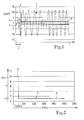
- FIG. 1 is a diagram of the course 1 of a sensor signal of the sensor arrangement over the time t shown here in the detection of the rotational movement of a known from the prior art sensor wheel, z. B. for generating pulses for predetermined rotation angle, is determined.
- an area 2 defined as a standstill of the donor wheel, not shown here. This area 2 can be defined, for example, as a range below a predetermined limit f limit , as indicated in parallel in FIG.
- the FIG. 2 shows the curve 3 of a switching hysteresis H as a function of the frequency f in the evaluation of the sensor signal 1 after the FIG. 1 ,
- a relatively large switching hysteresis 4 is selected as Hyst0, so that vibrations 5 do not lead to some signals corrupting the measurement result.
- FIG. 3 is a combination of the fixed hysteresis H after the FIG. 2 shown with an amplitude-dependent hysteresis H.
- a curve 7 of the hysteresis H over the signal amplitude SA is shown.
- FIG. 4 is a flowchart for the operation of a sensor according to the invention including the determination of the basis of the FIGS. 1 to 3 explained switching hysteresis H shown.
- the large switching hysteresis Hyst0 is set.
- the measured signal amplitude SA see position 1 from the FIG. 1
- the hysteresis H the value H1.
- a new value for Hyst0 can be determined, which is used in a new standstill.
Landscapes
- Physics & Mathematics (AREA)
- General Physics & Mathematics (AREA)
- Indicating Or Recording The Presence, Absence, Or Direction Of Movement (AREA)
- Transmission And Conversion Of Sensor Element Output (AREA)
- Regulating Braking Force (AREA)
Claims (6)
- Procédé de saisie du déplacement d'un élément par rapport à un ensemble de capteurs, dans lequel
des signaux de commutation (1) sont évalués par un émetteur d'impulsions passé devant le capteur,
pendant l'évaluation, une adaptation d'une hystérèse de commutation (H) est réalisée en fonction des valeurs du signal de commutation (1),
une hystérèse de commutation relativement grande étant établie en tant qu'hystérèse initiale (Hyst0) lorsque l'élément se déplace depuis l'arrêt jusqu'en dessous d'une valeur limite prédéterminée et une hystérèse de commutation réduite (H1) s'établissant lorsque la valeur limite est dépassée,
caractérisé en ce que
l'amplitude du signal de commutation (1) mesurée préalablement intervient dans la détermination de l'hystérèse de commutation relativement grande utilisée comme hystérèse initiale (Hyst0). - Procédé selon la revendication 1, caractérisé en ce que la valeur limite (fGrenz) prédéterminée est la fréquence Grenz mesurée sur les signaux de commutation (1).
- Procédé selon les revendications 1 ou 2, caractérisé en ce que les signaux de commutation (1) d'une roue émettrice servant d'émetteurs d'impulsions sont évalués pour saisir le déplacement d'un élément rotatif.
- Procédé selon l'une des revendications 1 ou 2, caractérisé en ce que pour l'hystérèse de commutation (H1) réduite, une valeur fixe intervient après dépassement de la valeur limite (fGrenz).
- Ensemble de capteurs servant à mettre en oeuvre le procédé selon l'une des revendications 1 à 4, l'ensemble de capteurs étant configuré de manière à
évaluer des signaux de commutation (1) en fonction d'un émetteur d'impulsions passé devant le capteur,
lors de l'évaluation, pouvoir réaliser une adaptation d'une hystérèse de commutation (H) en fonction des valeurs du signal de commutation (1),
établir une hystérèse de commutation relativement grande en tant qu'hystérèse initiale (Hyst0) lorsque l'élément est déplacé depuis l'arrêt jusqu'en dessous d'une valeur limite prédéterminée et
établir une hystérèse de commutation (H1) réduite lorsque la valeur limite est dépassée,
l'ensemble de capteurs présentant des capteurs sans contact dotés d'éléments Hall ou d'éléments magnétorésistifs,
caractérisé en ce que
l'amplitude du signal de commutation (1) mesurée préalablement intervient dans la détermination de l'hystérèse de commutation relativement grande utilisée comme hystérèse initiale (Hyst0). - Ensemble de capteurs selon la revendication 5, caractérisé en ce que l'ensemble de capteurs est utilisé comme sonde de vitesse de rotation dans un véhicule automobile.
Applications Claiming Priority (3)
| Application Number | Priority Date | Filing Date | Title |
|---|---|---|---|
| DE10222205 | 2002-05-18 | ||
| DE10222205A DE10222205A1 (de) | 2002-05-18 | 2002-05-18 | Verfahren und Anordnung zur Erfassung der Bewegung eines Elements |
| PCT/DE2003/000926 WO2003098229A1 (fr) | 2002-05-18 | 2003-03-20 | Procede et systeme pour determiner la vitesse de rotation par hysteresis de commutation |
Publications (2)
| Publication Number | Publication Date |
|---|---|
| EP1508049A1 EP1508049A1 (fr) | 2005-02-23 |
| EP1508049B1 true EP1508049B1 (fr) | 2014-11-12 |
Family
ID=29285573
Family Applications (1)
| Application Number | Title | Priority Date | Filing Date |
|---|---|---|---|
| EP03720222.3A Expired - Lifetime EP1508049B1 (fr) | 2002-05-18 | 2003-03-20 | Procede et systeme pour determiner la vitesse de rotation par hysteresis de commutation |
Country Status (7)
| Country | Link |
|---|---|
| US (1) | US6967476B2 (fr) |
| EP (1) | EP1508049B1 (fr) |
| JP (1) | JP4473725B2 (fr) |
| KR (1) | KR101000729B1 (fr) |
| DE (1) | DE10222205A1 (fr) |
| PL (1) | PL374145A1 (fr) |
| WO (1) | WO2003098229A1 (fr) |
Families Citing this family (10)
| Publication number | Priority date | Publication date | Assignee | Title |
|---|---|---|---|---|
| US7365530B2 (en) * | 2004-04-08 | 2008-04-29 | Allegro Microsystems, Inc. | Method and apparatus for vibration detection |
| DE102004025776B3 (de) * | 2004-05-26 | 2005-07-21 | Infineon Technologies Ag | Verfahren zur Detektion von Störungen bei der Ermittlung der Drehgeschwindigkeit eines Rotors und Auswerteschaltung |
| DE102009034664B4 (de) * | 2009-07-24 | 2014-05-08 | Brose Fahrzeugteile Gmbh & Co. Kommanditgesellschaft, Hallstadt | Verfahren und Vorrichtung zur Ermittlung der Stellposition eines Verstellelements eines Kraftfahrzeugs |
| US9329057B2 (en) | 2012-05-31 | 2016-05-03 | Allegro Microsystems, Llc | Gear tooth sensor with peak and threshold detectors |
| US10822105B2 (en) | 2018-07-04 | 2020-11-03 | Pratt & Whitney Canada Corp. | Method and system for controlling a crossing threshold used in determining rotational speed of a propeller |
| FR3093176B1 (fr) | 2019-02-26 | 2021-01-22 | Continental Automotive | Procédé d’autorisation de mise à jour d’un capteur magnétique pour moteur thermique avec immunité aux perturbations magnétiques |
| US11125590B2 (en) | 2019-05-07 | 2021-09-21 | Allegro Microsystems, Llc | System and method for vibration detection with direction change response immunity using a magnetic field sensor |
| US11029176B2 (en) | 2019-05-07 | 2021-06-08 | Allegro Microsystems, Llc | System and method for vibration detection with no loss of position information using a magnetic field sensor |
| US11592455B2 (en) * | 2020-01-13 | 2023-02-28 | Woodward, Inc. | Adaptive voltage threshold for turbine engine |
| DE102023210763B3 (de) * | 2023-10-30 | 2024-12-19 | Continental Automotive Technologies GmbH | Ermitteln einer Bewegungsinformation eines Fahrzeugs |
Family Cites Families (9)
| Publication number | Priority date | Publication date | Assignee | Title |
|---|---|---|---|---|
| DE3930895A1 (de) | 1989-09-15 | 1991-03-28 | Fatec Fahrzeugtech Gmbh | Schaltung zur ermittlung der drehzahl eines rades |
| JP2876854B2 (ja) | 1991-10-25 | 1999-03-31 | 日本電気株式会社 | 電位検出回路 |
| JP3303439B2 (ja) | 1993-06-25 | 2002-07-22 | 株式会社デンソー | 波形整形回路 |
| US5754042A (en) * | 1994-06-20 | 1998-05-19 | General Motors Corporation | Magnetoresistive encoder for tracking the angular position of a rotating ferromagnetic target wheel |
| DE4434978B4 (de) | 1994-09-30 | 2007-08-23 | Continental Teves Ag & Co. Ohg | Aktiver Bewegungssensor |
| WO1998049564A1 (fr) | 1997-04-30 | 1998-11-05 | Continental Teves Ag & Co. Ohg | Systeme de detection de vitesse de rotation |
| DE19750304A1 (de) | 1997-11-13 | 1999-05-20 | Bosch Gmbh Robert | Vorrichtung zum Erfassen der Drehung eines Teils einschließlich der Drehrichtung |
| DE19961876A1 (de) | 1999-12-20 | 2001-06-28 | Micronas Gmbh | Verfahren zum Erfassen der Drehzahl und der Winkelstellung eines rotierenden Rades |
| US6346808B1 (en) * | 2000-02-28 | 2002-02-12 | Delphi Technologies, Inc. | Crankshaft position sensor |
-
2002
- 2002-05-18 DE DE10222205A patent/DE10222205A1/de not_active Withdrawn
-
2003
- 2003-03-20 JP JP2004505701A patent/JP4473725B2/ja not_active Expired - Fee Related
- 2003-03-20 KR KR1020047018547A patent/KR101000729B1/ko not_active Expired - Fee Related
- 2003-03-20 US US10/507,047 patent/US6967476B2/en not_active Expired - Fee Related
- 2003-03-20 PL PL03374145A patent/PL374145A1/xx not_active Application Discontinuation
- 2003-03-20 WO PCT/DE2003/000926 patent/WO2003098229A1/fr not_active Ceased
- 2003-03-20 EP EP03720222.3A patent/EP1508049B1/fr not_active Expired - Lifetime
Also Published As
| Publication number | Publication date |
|---|---|
| WO2003098229A1 (fr) | 2003-11-27 |
| EP1508049A1 (fr) | 2005-02-23 |
| PL374145A1 (en) | 2005-10-03 |
| US6967476B2 (en) | 2005-11-22 |
| US20050122098A1 (en) | 2005-06-09 |
| DE10222205A1 (de) | 2003-11-27 |
| JP4473725B2 (ja) | 2010-06-02 |
| JP2005526248A (ja) | 2005-09-02 |
| KR20040111630A (ko) | 2004-12-31 |
| KR101000729B1 (ko) | 2010-12-14 |
Similar Documents
| Publication | Publication Date | Title |
|---|---|---|
| EP1307709B1 (fr) | Detecteur de champ magnetique actif, son utilisation, procede et dispositif associes | |
| EP3311120B1 (fr) | Dispositif et procédé d'évaluation d'un signal provenant d'un capteur d'angle de rotation | |
| DE102013224098A1 (de) | Sensoranordnung zur Erfassung von Drehwinkeln an einem rotierenden Bauteil in einem Fahrzeug | |
| EP3721175B1 (fr) | Systeme de capteur permettant de determiner au moins une propriete de rotation d'un element tournant autour d'au moins un axe de rotation | |
| DE102011004366A1 (de) | Sensoranordnung zum Bestimmen eines Drehwinkels | |
| DE102015102013A1 (de) | Sensorvorrichtung mit einer Drehmomentsensoreinrichtung und einer Inkrementalsensoreinrichtung und Kraftfahrzeug mit einer solchen Sensorvorrichtung | |
| EP0417423A2 (fr) | Circuit pour la détection de la vitesse de rotation d'une roue | |
| EP1508049A1 (fr) | Procede et systeme pour determiner la vitesse de rotation par hysteresis de commutation | |
| WO2022101032A1 (fr) | Dispositif formant capteur de position inductif, dispositif d'entraînement | |
| DE10017061A1 (de) | Anordnung und Verfahren zur Drehwinkelerfassung | |
| EP3311106B1 (fr) | Procédé et circuit pour détecter un court-circuit de la bobine réceptrice sinus/cosinus d'un résolveur | |
| EP1511973B1 (fr) | Procede et ensemble de detection du mouvement d'un element | |
| DE10240705A1 (de) | Drehzahlmeßsystem | |
| EP1508050A1 (fr) | Procede et dispositif de detection du mouvement d'un element | |
| EP4248175B1 (fr) | Système de capteur pour la détermination d'au moins une caractéristique de rotation d'un élément tournant | |
| EP3312566B1 (fr) | Transducteur rotatif destiné à mesurer une variable d'état d'un objet rotatif | |
| WO2005111383A1 (fr) | Frein a hysteresis, destine notamment a un organe de positionnement electrique d'arbre a cames | |
| DE102013221191A1 (de) | Sensoranordnung zur Erfassung von Drehwinkeln an einem rotierenden Bauteil in einem Fahrzeug | |
| EP3311112B1 (fr) | Procédé et dispositif de traitement d'un signal | |
| DE102023128056A1 (de) | Messanordnung und Verfahren zur Bestimmung einer Winkelposition eines um eine Achse drehbaren Targets | |
| DE102024109336A1 (de) | Sensoreinrichtung zur Ermittlung einer Lage eines Bauteils einer Fahrzeugkomponente, Steuerungsanordnung, Fahrzeugkomponente, Kraftfahrzeug und Verfahren | |
| EP1234367A1 (fr) | Dispositif et procede pour detecter une situation de coincement au niveau de surfaces d'automobile | |
| EP1828723A1 (fr) | Procede pour determiner un point de commutation lors de l'analyse des signaux d'un ensemble capteur magnetique | |
| WO2006131418A1 (fr) | Ensemble capteur de courant de foucault |
Legal Events
| Date | Code | Title | Description |
|---|---|---|---|
| PUAI | Public reference made under article 153(3) epc to a published international application that has entered the european phase |
Free format text: ORIGINAL CODE: 0009012 |
|
| 17P | Request for examination filed |
Effective date: 20041220 |
|
| AK | Designated contracting states |
Kind code of ref document: A1 Designated state(s): AT BE BG CH CY CZ DE DK EE ES FI FR GB GR HU IE IT LI LU MC NL PT RO SE SI SK TR |
|
| RBV | Designated contracting states (corrected) |
Designated state(s): DE FR GB HU IT |
|
| 17Q | First examination report despatched |
Effective date: 20101007 |
|
| GRAP | Despatch of communication of intention to grant a patent |
Free format text: ORIGINAL CODE: EPIDOSNIGR1 |
|
| INTG | Intention to grant announced |
Effective date: 20140528 |
|
| GRAP | Despatch of communication of intention to grant a patent |
Free format text: ORIGINAL CODE: EPIDOSNIGR1 |
|
| INTG | Intention to grant announced |
Effective date: 20140814 |
|
| GRAS | Grant fee paid |
Free format text: ORIGINAL CODE: EPIDOSNIGR3 |
|
| GRAA | (expected) grant |
Free format text: ORIGINAL CODE: 0009210 |
|
| AK | Designated contracting states |
Kind code of ref document: B1 Designated state(s): DE FR GB HU IT |
|
| REG | Reference to a national code |
Ref country code: GB Ref legal event code: FG4D Free format text: NOT ENGLISH |
|
| REG | Reference to a national code |
Ref country code: DE Ref legal event code: R096 Ref document number: 50315155 Country of ref document: DE Effective date: 20141224 |
|
| REG | Reference to a national code |
Ref country code: DE Ref legal event code: R097 Ref document number: 50315155 Country of ref document: DE |
|
| PLBE | No opposition filed within time limit |
Free format text: ORIGINAL CODE: 0009261 |
|
| STAA | Information on the status of an ep patent application or granted ep patent |
Free format text: STATUS: NO OPPOSITION FILED WITHIN TIME LIMIT |
|
| 26N | No opposition filed |
Effective date: 20150813 |
|
| GBPC | Gb: european patent ceased through non-payment of renewal fee |
Effective date: 20150320 |
|
| PG25 | Lapsed in a contracting state [announced via postgrant information from national office to epo] |
Ref country code: IT Free format text: LAPSE BECAUSE OF FAILURE TO SUBMIT A TRANSLATION OF THE DESCRIPTION OR TO PAY THE FEE WITHIN THE PRESCRIBED TIME-LIMIT Effective date: 20141112 |
|
| REG | Reference to a national code |
Ref country code: FR Ref legal event code: ST Effective date: 20151130 |
|
| PG25 | Lapsed in a contracting state [announced via postgrant information from national office to epo] |
Ref country code: GB Free format text: LAPSE BECAUSE OF NON-PAYMENT OF DUE FEES Effective date: 20150320 |
|
| PG25 | Lapsed in a contracting state [announced via postgrant information from national office to epo] |
Ref country code: FR Free format text: LAPSE BECAUSE OF NON-PAYMENT OF DUE FEES Effective date: 20150331 |
|
| PG25 | Lapsed in a contracting state [announced via postgrant information from national office to epo] |
Ref country code: HU Free format text: LAPSE BECAUSE OF FAILURE TO SUBMIT A TRANSLATION OF THE DESCRIPTION OR TO PAY THE FEE WITHIN THE PRESCRIBED TIME-LIMIT; INVALID AB INITIO Effective date: 20030320 |
|
| PGFP | Annual fee paid to national office [announced via postgrant information from national office to epo] |
Ref country code: DE Payment date: 20170529 Year of fee payment: 15 |
|
| REG | Reference to a national code |
Ref country code: DE Ref legal event code: R119 Ref document number: 50315155 Country of ref document: DE |
|
| PG25 | Lapsed in a contracting state [announced via postgrant information from national office to epo] |
Ref country code: DE Free format text: LAPSE BECAUSE OF NON-PAYMENT OF DUE FEES Effective date: 20181002 |