EP1508268A1 - Presse à balles rondes - Google Patents
Presse à balles rondes Download PDFInfo
- Publication number
- EP1508268A1 EP1508268A1 EP04019549A EP04019549A EP1508268A1 EP 1508268 A1 EP1508268 A1 EP 1508268A1 EP 04019549 A EP04019549 A EP 04019549A EP 04019549 A EP04019549 A EP 04019549A EP 1508268 A1 EP1508268 A1 EP 1508268A1
- Authority
- EP
- European Patent Office
- Prior art keywords
- bale
- round
- weighing
- round baler
- baler according
- Prior art date
- Legal status (The legal status is an assumption and is not a legal conclusion. Google has not performed a legal analysis and makes no representation as to the accuracy of the status listed.)
- Granted
Links
- 238000005303 weighing Methods 0.000 claims abstract description 77
- 238000005096 rolling process Methods 0.000 claims abstract description 19
- 238000000034 method Methods 0.000 claims description 10
- 238000013016 damping Methods 0.000 claims description 3
- 238000004146 energy storage Methods 0.000 claims description 2
- 238000005259 measurement Methods 0.000 description 11
- 238000003825 pressing Methods 0.000 description 4
- 230000035939 shock Effects 0.000 description 4
- 239000006096 absorbing agent Substances 0.000 description 2
- 238000005452 bending Methods 0.000 description 2
- 230000006835 compression Effects 0.000 description 2
- 238000007906 compression Methods 0.000 description 2
- 230000005484 gravity Effects 0.000 description 2
- 238000010276 construction Methods 0.000 description 1
- 230000003111 delayed effect Effects 0.000 description 1
- 238000002474 experimental method Methods 0.000 description 1
- 230000010355 oscillation Effects 0.000 description 1
Images

Classifications
-
- G—PHYSICS
- G01—MEASURING; TESTING
- G01G—WEIGHING
- G01G19/00—Weighing apparatus or methods adapted for special purposes not provided for in the preceding groups
- G01G19/08—Weighing apparatus or methods adapted for special purposes not provided for in the preceding groups for incorporation in vehicles
-
- A—HUMAN NECESSITIES
- A01—AGRICULTURE; FORESTRY; ANIMAL HUSBANDRY; HUNTING; TRAPPING; FISHING
- A01F—PROCESSING OF HARVESTED PRODUCE; HAY OR STRAW PRESSES; DEVICES FOR STORING AGRICULTURAL OR HORTICULTURAL PRODUCE
- A01F15/00—Baling presses for straw, hay or the like
- A01F15/08—Details
- A01F15/0875—Discharge devices
- A01F15/0883—Discharge devices for round balers
-
- A—HUMAN NECESSITIES
- A01—AGRICULTURE; FORESTRY; ANIMAL HUSBANDRY; HUNTING; TRAPPING; FISHING
- A01F—PROCESSING OF HARVESTED PRODUCE; HAY OR STRAW PRESSES; DEVICES FOR STORING AGRICULTURAL OR HORTICULTURAL PRODUCE
- A01F15/00—Baling presses for straw, hay or the like
- A01F15/08—Details
- A01F15/0875—Discharge devices
- A01F2015/0891—Weighing the finished bale before falling to ground
Definitions
- the invention relates to a round baler with a weighing sensors on a Abrollvorraum supporting weighing platform for detecting the weight of a fully bound Round bale.
- the round baler described above can be found in DE 199 10 555 A1.
- the weighing of a round bale during the rolling motion on a carried off the ground supported rolling device This is on the unwinding device about halfway Length pivotally hinged in the direction of travel to the rear weighing platform.
- the Weighing platform rests on one or more weighing sensors attached to the unwinding device from.
- the weighing should be done at the end of the unwinding device.
- This is above the weighing sensor a provided electrical override switch, which generates a signal when the ball center of gravity over the Operating direction of the weighing sensor is running.
- this device is basically a determination of the Bale weight possible.
- the bale for the duration of a measurement on the Unwinding be stopped.
- the unwinding should not be on the ground support, but the round bale is discharged after bale discharge in a relatively shallow trough or kept in a pair of scissors.
- the Weighing device arranged here between round baler and unwinding,
- the invention is based on the object, the weighing device described above in terms of Improve measurement accuracy and develop a simpler and more cost-effective solution.
- This object is achieved in that on the weighing platform additional resources attached, which brake the round bale against rolling on the weighing platform and / or hold and release after completion of the weighing in the unwinding direction.
- the round bale is temporarily braked targeted on the weighing platform and / or stopped to ensure a rapid measurement after the settling time of the system.
- the invention uses the process that the round bale immediately after ejection from the Press housing anyway reverses its direction of rotation and thus is briefly at a standstill. The Exploiting this process minimizes the time delay through the weighing process. Since the Abrollvorraum supported during the weighing and Abrollvorganges on the ground, arise despite the built-in weighing platform no load changes for the press. Through the ground contact Sound vibrations faster. Due to the inventive design of the weighing platform ensures that the sum of all forces on the weighing platform remains in balance and none new disturbances arise.
- a preferred, particularly accurate measurement embodiment is that the additional means a bale arresting device, which in its working position at a distance above the Contact area on the round bale attacks and on the round bales one opposite to the unwinding direction directed force exerts while the bale arrester in its rest position out of engagement with the Round bale is. Due to the ball standstill on the weighing platform are at a standstill period of 2 to 3 seconds, all disturbances subsided, so that deviations of less than 1% in relation to the weight of a bale can be reached with little effort.
- Another embodiment of the invention provides that the additional means a Ballenabbremsvorraum comprising the round bales at reduced rotational speed over the weighing platform is running.
- the weighing platform which overruns the round bale slowly, does not need any Ripple switch, but captures the weight signals on a measuring section (measuring range) between the front and rear load cells.
- the load cells give already during slow rolling over the Balen's weight signals, which can be further processed for accurate bale weight measurement.
- Prerequisite is that the bale runs so slowly that the entire bale contact area for a short time is completely on the weighing platform.
- accurate readings are independent of the Focus of round bale or different bale centers of round bale on the Reached weighing platform.
- the advantage of this solution is that the throughput of the Round baler (bale / time unit) is minimized minimally despite the bale weighing.
- a functionally safe and time-saving solution is that the ball-braking device and / or the bale stopping device prior to opening the rear housing into its extended one Working position moves / drives, and that the rear housing is only closable after the Baleabbremsvoruze and / or the bale arrestor is in its rest position. This is ensures that the movement of the ball-braking device and / or the bale-stopping device does not collide with the movement of the rear housing and on the other hand will / will Bale arrestor and / or the bale brake in time to their working position brought or in their rest position.
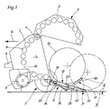
- the round baler has a two-part press housing, consisting of a front housing 1, which rests on a chassis 2 frame-fixed and a rear housing 3, which is an upper Swivel axis 4 for bale ejection in a discharge position 5 is hinged.
- On the front housing 1 engages a drawbar 6 to connect to a tractor, not shown.
- the round baler is via a non-illustrated propeller shaft connection drivingly coupled to the tractor.
- in the Press housing becomes a constant-diameter press room 7 of fixed but driven Press rolls 8 formed. But the press room 7 can also by rod chain conveyors or belts or Mixed forms are limited and also be of variable size - the design is for the present Invention insignificant.
- the stalk is picked up by a collector 9 from the ground and conveyed through an inlet opening 10 in the pressing space 7.
- a rearwardly extending unwinding device 11 with a weighing device 12 for a ejected from the front housing 1 round bale 13th arranged.
- the terms “front” and “rear” refer to the direction of travel of the Round baler, which is indicated by arrow 14.
- the unwinding device 11 consists in this example of two spaced apart Arms 15, 16, the front ends 17 are connected by a cross tube 18 firmly together.
- the Booms 15, 16 are a horizontal axis transverse to the direction of travel of the round baler 19 pivoted on pin 20 on the front housing 1 or on the chassis.
- the arms 15, 16 are drawn in their lower working position 21, in which the boom ends 22 on the ground rest and form an inclined plane for a round bale 13 rolling on it. At rest the unwinding device 11 assumes an upwardly pivoted, not shown position.
- the weighing device 12 begins immediately behind the pivot axis 19 of the rolling device 11 and consists of a weighing platform 23, which is arranged over two front, spaced apart side by side Load cells 24 and two rear, spaced apart next to each other detached load cells 25 on both sides the arms 15, 16 is supported.
- the load cells 24, 25 are designed in this example as a bending beam, which are attached at one end to the boom 15, 16 and the other end to the weighing platform 23.
- 16 overload protection screws 26 are provided, which is the deflection of the bending beam down limit.
- the weighing platform 23 consists of two juxtaposed longitudinal members 27, 28, in a the distance of the boom 15, 16 corresponding distance by front 29 and rear Cross struts 30 are firmly connected.
- the bale situation on the To stabilize weighing platform 23 are 23 side guide rollers 31 on both sides of the balance bridge arranged at a distance that is slightly larger than the bale width.
- a bale arrester 32 is provided between the arms 15, 16 is arranged.
- the bale arrester 32 is formed as a U-shaped bracket and consists of two arms 33, 34, whose rear ends are connected by a transverse web 35 fixed to each other, which is parallel to the axis of the 19th is located. Both arms 33, 34 are after about a quarter of their length from their front end 38 of Seen via bolt / tab connections 36 attached to the rear cross member 18, so that the Bale stopping device 32 is pivotable about the axis of rotation 37.
- both arms 33, 34 each connected to a hydraulic cylinder 39, the other end in each case on the transverse strut 17 and are adapted to the bale arrester 32 from her in dashed line drawn rest position 40 ( Figure 1), in which these below or in the rolling plane of the round bale 13th is to move in a drawn in full line working position 41, in which this with the arms 15, 16 forms an obtuse angle and in the Abrollweg of the round bale 13 approximately after a 1/3 of the Balls diameter protrudes seen from the ball contact surface, see through arrow X. marked distance.
- the hydraulic cylinders 39 are connected to an unillustrated hydraulic system for raising and lowering the Rear housing 3 connected. Due to the low operating force, the bale stop device 32 priority, i. moved to its working position 21 before opening the rear housing 3. Furthermore, the Control designed so that the rear housing 3 can be closed again after the Bale stopping device 32 in its rest position 40 and the round bale 13, the rolling device 11th has left.
- the operation of the weighing device 12 is as follows:
- the bale arrester 32 is at rest 40 (Fig.1). is a bale 13 in the round baler is finished pressed and wrapped, the bale arrester 32nd before the bale discharge in their working position 41, see Fig. 1, 2 pivoted.
- the after opening the Rear housing 3 ejected round bales 13 runs on the weighing platform 23 and is characterized by the Bale stop device 32 stopped in its rolling motion.
- a hydraulic accumulator 42 as a damping element be arranged.
- the entire ball contact surface is located on the weighing platform 23.
- Each of the four load cells 24, 25 provides weight signals, which in a non-illustrated, known per se Calculator or microprocessor evaluated and related.
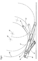
- the hydraulic cylinder 39 by compression springs 43 and shock absorbers 44 is replaced to form a ball braking device 45.
- the compression springs 43 and the shock absorbers 44 are arranged on both sides within the boom 46 and on the weighing platform 47 and on the Ballenabbremsvorraum 45 hinged and designed so that a against the bale brake device 45 rolling round bales 48 in its rolling motion between front 24 and rear load cells 25, (Fig. 2) is braked, but not quite come to a halt, because the ball braking device 45 by the backward force component of the round bale 48 drawn from its solid line Dodge position during weighing in the dotted line position. This is despite Weighing during the delayed rolling of the round bale 48 within the measuring range, see Ballenheddlinglagen 49, 50, stable weight measurements of the round bale 48 with high accuracy possible.
- the actual stopping / weighing position of the round bale 13 a delay line, while the bale arrester 32 by suitable means, such as a between bale arrester 32 and weighing platform 23rd arranged spring element, an energy storage and / or a damping element in addition as Ballenabbremsvorraum, which the rotational speed of the round bale 13 after the Bale ejection from the round baler and before emergence or when crossing the Weighing platform (23) reduced. Although this reduces shock loads, however, the Extend time until restart of a new pressing process.
Landscapes
- Life Sciences & Earth Sciences (AREA)
- Environmental Sciences (AREA)
- Physics & Mathematics (AREA)
- General Physics & Mathematics (AREA)
- Preliminary Treatment Of Fibers (AREA)
Applications Claiming Priority (2)
| Application Number | Priority Date | Filing Date | Title |
|---|---|---|---|
| DE10338349 | 2003-08-21 | ||
| DE10338349A DE10338349A1 (de) | 2003-01-21 | 2003-08-21 | Rundballenpresse |
Publications (2)
| Publication Number | Publication Date |
|---|---|
| EP1508268A1 true EP1508268A1 (fr) | 2005-02-23 |
| EP1508268B1 EP1508268B1 (fr) | 2017-04-12 |
Family
ID=34042220
Family Applications (1)
| Application Number | Title | Priority Date | Filing Date |
|---|---|---|---|
| EP04019549.7A Expired - Lifetime EP1508268B1 (fr) | 2003-08-21 | 2004-08-18 | Presse à balles rondes |
Country Status (1)
| Country | Link |
|---|---|
| EP (1) | EP1508268B1 (fr) |
Cited By (5)
| Publication number | Priority date | Publication date | Assignee | Title |
|---|---|---|---|---|
| US9297688B2 (en) | 2012-12-21 | 2016-03-29 | Cnh Industrial America Llc | Weighing round bales |
| US10036663B2 (en) | 2014-12-24 | 2018-07-31 | Cnh Industrial America Llc | Weighing round bales |
| EP3677113A1 (fr) * | 2019-01-02 | 2020-07-08 | Deere & Company | Système de mesure et de contrôle du poids des balles à l'aide d'une grille de levage |
| EP3760031A1 (fr) * | 2019-06-27 | 2021-01-06 | Deere & Company | Presse à balles rondes et procédé de fonctionnement d'une presse à balles rondes |
| WO2022023016A1 (fr) * | 2020-07-27 | 2022-02-03 | Idough Investment Company Ltd. | Machine d'emballage de balles et mécanisme de déchargement |
Citations (5)
| Publication number | Priority date | Publication date | Assignee | Title |
|---|---|---|---|---|
| DE4208091A1 (de) * | 1992-03-13 | 1993-10-07 | Helmut Schenke | Vorrichtung zum Pressen und Einwickeln von Ballen |
| US5811739A (en) * | 1997-03-28 | 1998-09-22 | Palmore; Donald | Mobile bale weighing device |
| US5913801A (en) * | 1995-11-22 | 1999-06-22 | Robert Bosch Gmbh | Agricultural baler, and method of baling |
| US6457295B1 (en) * | 1999-03-10 | 2002-10-01 | Lely Welger Maschinenfabrik Gmbh | Round baler |
| EP1424000A1 (fr) * | 2002-11-26 | 2004-06-02 | Deere & Company | Dispositif pour l'ejection des balles d'une presse a balles cylindriques |
-
2004
- 2004-08-18 EP EP04019549.7A patent/EP1508268B1/fr not_active Expired - Lifetime
Patent Citations (5)
| Publication number | Priority date | Publication date | Assignee | Title |
|---|---|---|---|---|
| DE4208091A1 (de) * | 1992-03-13 | 1993-10-07 | Helmut Schenke | Vorrichtung zum Pressen und Einwickeln von Ballen |
| US5913801A (en) * | 1995-11-22 | 1999-06-22 | Robert Bosch Gmbh | Agricultural baler, and method of baling |
| US5811739A (en) * | 1997-03-28 | 1998-09-22 | Palmore; Donald | Mobile bale weighing device |
| US6457295B1 (en) * | 1999-03-10 | 2002-10-01 | Lely Welger Maschinenfabrik Gmbh | Round baler |
| EP1424000A1 (fr) * | 2002-11-26 | 2004-06-02 | Deere & Company | Dispositif pour l'ejection des balles d'une presse a balles cylindriques |
Cited By (7)
| Publication number | Priority date | Publication date | Assignee | Title |
|---|---|---|---|---|
| US9297688B2 (en) | 2012-12-21 | 2016-03-29 | Cnh Industrial America Llc | Weighing round bales |
| US9585310B2 (en) | 2012-12-21 | 2017-03-07 | Cnh Industrial America Llc | Weighing round bales |
| US10036663B2 (en) | 2014-12-24 | 2018-07-31 | Cnh Industrial America Llc | Weighing round bales |
| EP3677113A1 (fr) * | 2019-01-02 | 2020-07-08 | Deere & Company | Système de mesure et de contrôle du poids des balles à l'aide d'une grille de levage |
| EP3760031A1 (fr) * | 2019-06-27 | 2021-01-06 | Deere & Company | Presse à balles rondes et procédé de fonctionnement d'une presse à balles rondes |
| US11641807B2 (en) * | 2019-06-27 | 2023-05-09 | Deere & Company | Round baler |
| WO2022023016A1 (fr) * | 2020-07-27 | 2022-02-03 | Idough Investment Company Ltd. | Machine d'emballage de balles et mécanisme de déchargement |
Also Published As
| Publication number | Publication date |
|---|---|
| EP1508268B1 (fr) | 2017-04-12 |
Similar Documents
| Publication | Publication Date | Title |
|---|---|---|
| DE69516447T2 (de) | Vorrichtung zum Sortieren und Zusammenbinden von Blumen | |
| CH630315A5 (en) | Scraper apparatus for reversible belt bands | |
| EP1364574B1 (fr) | Presse à balles rondes | |
| DE10257252A1 (de) | Presse, insbesondere Rundballenpresse | |
| EP1795065A1 (fr) | Press à balles avec dispositif de mesure de l'humidité | |
| EP1707044A1 (fr) | Dispositif de chargement | |
| DE4240449C2 (de) | Kippvorrichtung für ein Fahrerhaus von Nutzfahrzeugen | |
| DE2530249A1 (de) | Wickelballenpresse | |
| DE10153539A1 (de) | Rundballenpresse | |
| DE3247661A1 (de) | Fahrbare rollballengrosspresse fuer landwirtschaftliche halmgueter | |
| CH649958A5 (de) | Transportvorrichtung mit haengender kabine. | |
| EP1508268B1 (fr) | Presse à balles rondes | |
| EP0803321A1 (fr) | Butée, notamment pour des appareils automatiques d'usinage et de transport | |
| DE3232124C2 (fr) | ||
| DE2252451B2 (de) | Vorrichtung zum zufuehren empfindlicher stabfoermiger werkstuecke auf eine foerderbahn | |
| DE10021352A1 (de) | Rundballenpresse für landwirtschaftliche Halmgüter | |
| EP1726204B1 (fr) | Presse et appareil pour envelopper des balles rondes | |
| EP3960658A1 (fr) | Véhicule de chargement pour un agencement de stockage empilé | |
| DE10338349A1 (de) | Rundballenpresse | |
| DE69412686T2 (de) | Fahrbares Stapelgerät für Ballen | |
| EP0516005B1 (fr) | Charrue comportant un dispositif de sécurité pour l'age | |
| CH671909A5 (fr) | ||
| DE7825062U1 (de) | Niederhubwagen | |
| DE102012017573A1 (de) | Presse zum Brikettieren von körnigem Material | |
| EP2163149B1 (fr) | Dispositif d'introduction pour un agrégat de hachage d'une récolteuse-hacheuse |
Legal Events
| Date | Code | Title | Description |
|---|---|---|---|
| PUAI | Public reference made under article 153(3) epc to a published international application that has entered the european phase |
Free format text: ORIGINAL CODE: 0009012 |
|
| AK | Designated contracting states |
Kind code of ref document: A1 Designated state(s): AT BE BG CH CY CZ DE DK EE ES FI FR GB GR HU IE IT LI LU MC NL PL PT RO SE SI SK TR |
|
| AX | Request for extension of the european patent |
Extension state: AL HR LT LV MK |
|
| 17P | Request for examination filed |
Effective date: 20050823 |
|
| AKX | Designation fees paid |
Designated state(s): DE FR GB NL |
|
| RIC1 | Information provided on ipc code assigned before grant |
Ipc: A01F 15/08 20060101AFI20130307BHEP Ipc: G01G 19/08 20060101ALI20130307BHEP |
|
| GRAP | Despatch of communication of intention to grant a patent |
Free format text: ORIGINAL CODE: EPIDOSNIGR1 |
|
| INTG | Intention to grant announced |
Effective date: 20130412 |
|
| RAP1 | Party data changed (applicant data changed or rights of an application transferred) |
Owner name: LELY VERMEER MASCHINENFABRIK GMBH |
|
| INTC | Intention to grant announced (deleted) | ||
| GRAP | Despatch of communication of intention to grant a patent |
Free format text: ORIGINAL CODE: EPIDOSNIGR1 |
|
| INTG | Intention to grant announced |
Effective date: 20161125 |
|
| RAP1 | Party data changed (applicant data changed or rights of an application transferred) |
Owner name: LELY MASCHINENFABRIK GMBH |
|
| GRAS | Grant fee paid |
Free format text: ORIGINAL CODE: EPIDOSNIGR3 |
|
| GRAA | (expected) grant |
Free format text: ORIGINAL CODE: 0009210 |
|
| AK | Designated contracting states |
Kind code of ref document: B1 Designated state(s): DE FR GB NL |
|
| REG | Reference to a national code |
Ref country code: GB Ref legal event code: FG4D Free format text: NOT ENGLISH |
|
| REG | Reference to a national code |
Ref country code: DE Ref legal event code: R081 Ref document number: 502004015502 Country of ref document: DE Owner name: FORAGE COMPANY B.V., NL Free format text: FORMER OWNER: WELGER MASCHINENFABRIK GMBH, 38304 WOLFENBUETTEL, DE |
|
| REG | Reference to a national code |
Ref country code: DE Ref legal event code: R096 Ref document number: 502004015502 Country of ref document: DE |
|
| REG | Reference to a national code |
Ref country code: NL Ref legal event code: MP Effective date: 20170412 |
|
| REG | Reference to a national code |
Ref country code: FR Ref legal event code: PLFP Year of fee payment: 14 |
|
| PG25 | Lapsed in a contracting state [announced via postgrant information from national office to epo] |
Ref country code: NL Free format text: LAPSE BECAUSE OF FAILURE TO SUBMIT A TRANSLATION OF THE DESCRIPTION OR TO PAY THE FEE WITHIN THE PRESCRIBED TIME-LIMIT Effective date: 20170412 |
|
| PGFP | Annual fee paid to national office [announced via postgrant information from national office to epo] |
Ref country code: GB Payment date: 20170829 Year of fee payment: 14 Ref country code: DE Payment date: 20170829 Year of fee payment: 14 Ref country code: FR Payment date: 20170825 Year of fee payment: 14 |
|
| REG | Reference to a national code |
Ref country code: DE Ref legal event code: R097 Ref document number: 502004015502 Country of ref document: DE |
|
| PLBE | No opposition filed within time limit |
Free format text: ORIGINAL CODE: 0009261 |
|
| STAA | Information on the status of an ep patent application or granted ep patent |
Free format text: STATUS: NO OPPOSITION FILED WITHIN TIME LIMIT |
|
| 26N | No opposition filed |
Effective date: 20180115 |
|
| REG | Reference to a national code |
Ref country code: DE Ref legal event code: R081 Ref document number: 502004015502 Country of ref document: DE Owner name: FORAGE COMPANY B.V., NL Free format text: FORMER OWNER: LELY MASCHINENFABRIK GMBH, 38304 WOLFENBUETTEL, DE |
|
| REG | Reference to a national code |
Ref country code: GB Ref legal event code: 732E Free format text: REGISTERED BETWEEN 20180607 AND 20180613 |
|
| REG | Reference to a national code |
Ref country code: DE Ref legal event code: R119 Ref document number: 502004015502 Country of ref document: DE |
|
| GBPC | Gb: european patent ceased through non-payment of renewal fee |
Effective date: 20180818 |
|
| PG25 | Lapsed in a contracting state [announced via postgrant information from national office to epo] |
Ref country code: DE Free format text: LAPSE BECAUSE OF NON-PAYMENT OF DUE FEES Effective date: 20190301 |
|
| PG25 | Lapsed in a contracting state [announced via postgrant information from national office to epo] |
Ref country code: FR Free format text: LAPSE BECAUSE OF NON-PAYMENT OF DUE FEES Effective date: 20180831 |
|
| PG25 | Lapsed in a contracting state [announced via postgrant information from national office to epo] |
Ref country code: GB Free format text: LAPSE BECAUSE OF NON-PAYMENT OF DUE FEES Effective date: 20180818 |