EP3760031A1 - Presse à balles rondes et procédé de fonctionnement d'une presse à balles rondes - Google Patents
Presse à balles rondes et procédé de fonctionnement d'une presse à balles rondes Download PDFInfo
- Publication number
- EP3760031A1 EP3760031A1 EP20181671.7A EP20181671A EP3760031A1 EP 3760031 A1 EP3760031 A1 EP 3760031A1 EP 20181671 A EP20181671 A EP 20181671A EP 3760031 A1 EP3760031 A1 EP 3760031A1
- Authority
- EP
- European Patent Office
- Prior art keywords
- ejection
- round baler
- holding roller
- housing part
- flap
- Prior art date
- Legal status (The legal status is an assumption and is not a legal conclusion. Google has not performed a legal analysis and makes no representation as to the accuracy of the status listed.)
- Granted
Links
Images



Classifications
-
- A—HUMAN NECESSITIES
- A01—AGRICULTURE; FORESTRY; ANIMAL HUSBANDRY; HUNTING; TRAPPING; FISHING
- A01F—PROCESSING OF HARVESTED PRODUCE; HAY OR STRAW PRESSES; DEVICES FOR STORING AGRICULTURAL OR HORTICULTURAL PRODUCE
- A01F15/00—Baling presses for straw, hay or the like
- A01F15/08—Details
- A01F15/0875—Discharge devices
- A01F15/0883—Discharge devices for round balers
-
- A—HUMAN NECESSITIES
- A01—AGRICULTURE; FORESTRY; ANIMAL HUSBANDRY; HUNTING; TRAPPING; FISHING
- A01F—PROCESSING OF HARVESTED PRODUCE; HAY OR STRAW PRESSES; DEVICES FOR STORING AGRICULTURAL OR HORTICULTURAL PRODUCE
- A01F15/00—Baling presses for straw, hay or the like
- A01F15/08—Details
- A01F15/0841—Drives for balers
- A01F15/085—Drives for balers for round balers
-
- A—HUMAN NECESSITIES
- A01—AGRICULTURE; FORESTRY; ANIMAL HUSBANDRY; HUNTING; TRAPPING; FISHING
- A01F—PROCESSING OF HARVESTED PRODUCE; HAY OR STRAW PRESSES; DEVICES FOR STORING AGRICULTURAL OR HORTICULTURAL PRODUCE
- A01F15/00—Baling presses for straw, hay or the like
- A01F15/08—Details
- A01F15/18—Endless belts, rolls or the like
-
- A—HUMAN NECESSITIES
- A01—AGRICULTURE; FORESTRY; ANIMAL HUSBANDRY; HUNTING; TRAPPING; FISHING
- A01F—PROCESSING OF HARVESTED PRODUCE; HAY OR STRAW PRESSES; DEVICES FOR STORING AGRICULTURAL OR HORTICULTURAL PRODUCE
- A01F15/00—Baling presses for straw, hay or the like
- A01F15/08—Details
- A01F15/18—Endless belts, rolls or the like
- A01F2015/186—Constructional details of rollers or the bearings of the rollers of the press chamber
Definitions
- the invention relates to a round baler according to the preamble of independent claim 1 and a method for a round baler according to the preamble of independent claim 8.
- Round balers are known.
- agricultural crops for example straw, grass or grain
- a round bale and wrapped with a wrapping material, for example net, film or twine.
- Such round balers have a receiving and feeding device for the crop to be pressed, through which the crop is introduced into a feed opening of a pressing chamber.
- the round baler comprises a housing, wherein the housing can in particular be designed in two parts.
- the housing has a housing part and an ejection flap mounted on this housing part so as to be pivotable about a bearing axis.
- the pressing chamber comprises one or more pressing means which are distributed on or on the housing part and the ejection flap and which delimit the pressing chamber on the circumferential side.
- the housing part forms a front part of the press chamber and the discharge flap forms a rear part of the press chamber.
- an engagement effect in particular a rotation-generating or rotation-maintaining engagement effect, can be generated on a round bale located in the pressing chamber.
- the ejection flap can be pivoted by means of a first adjusting device in such a way that when the ejection flap is opened an ejection opening can be formed between the housing part and the ejection flap.
- a dimension of the ejection opening can be adjusted, in particular adjusted and / or changed, by means of the first adjusting device.
- the EP 3 162 188 A1 discloses a round baler with an ejection flap which has a freely rotatably mounted support roller upstream of the pressing means.
- the EP 3 162 187 A1 discloses a round baler in which the pressing means of the ejection flap delimiting an ejection opening can be decoupled from the drive via a clutch. Both the freely rotatably mounted support roller and the uncoupled and thus freely rotatable pressing means are there to hold or support and / or brake the round bale during ejection with the ejection flap and to prevent damage to the wrapping material.
- An essential problem of the known round balers is that the round bale is held and / or braked during unloading with the discharge flap, whereby the round bale is pressed against the housing part, for example.
- the wrapping material of a round bale wrapped with a wrapping material can be damaged by the housing part, in particular the delimiting pressing means.
- the known round balers are designed or designed too complicated in terms of construction, so that components of the ejection flap are heavily stressed due to the forces acting, for example the bearing of the ejection flap or the support roller.
- the guidance of the holding roller must also be coordinated with the movement or setting of the ejection flap, which is very complex in terms of process technology.
- a round baler with a housing has a housing part and an ejection flap mounted on this housing part so as to be pivotable about a bearing axis, in particular an upper articulation axis.
- Pressing means in particular drivable pressing means, which delimit a pressing chamber on the circumferential side, are distributed on the housing part and the ejection flap.
- the ejection flap is adjustable, in particular adjustable and / or pivotable by means of a first adjusting device in such a way that when the ejection flap is opened, an ejection opening can be formed between the housing part and the ejection flap and a dimension of the ejection opening is adjustable, in particular adjustable and / or changeable.
- the housing part further comprises a holding roller.
- the holding roller is arranged adjustable between a rest position and a working position, in particular adjustable and / or movable and / or displaceable or decoupled. In the working position, the holding roller assumes a position that delimits the ejection opening, preferably for the round bale, particularly preferably for the round bale wrapped with wrapping material.
- the round baler can comprise a size-invariable baling chamber.
- the pressing means can be designed as a pressing roller, in particular a multiplicity of pressing rollers running parallel to one another for pressing the crop.
- the axes of rotation of the press rollers can lie on an arc and at least one of the press rollers can be driven.
- the arrangement of the press rollers in the baling chamber can correspond to a cylindrical shape, so that the press rollers are arranged cylindrically around the round bale and form a cylindrical peripheral surface.
- the Round baler also be designed with a variable-size press chamber or as a round baler with variable press chamber, wherein the pressing means can then be designed as belts, belts or chain arrangements.
- the unloading process can begin with the opening of the ejection flap and end with the closing of the ejection flap after unloading and holding the completely pressed round bale.
- the first setting device can be designed as a lifting cylinder or a pivoting cylinder.
- the lifting cylinder or swivel cylinder can for example be actuated electrically, mechanically or pneumatically, in particular designed as a hydraulic or pneumatic lifting cylinder or swivel cylinder.
- the first setting device can also be designed as an electric motor, for example a spindle motor or servomotor. A corresponding arrangement with a cable pull is also conceivable in order to make the actuation purely mechanical.
- the dimension of the ejection opening can be a diameter of the ejection opening or a distance between the pressing means of the housing part delimiting the ejection opening and the ejection flap.
- the round baler preferably the housing, particularly preferably the housing part, can comprise a frame and / or a chassis.
- the housing, preferably the housing part, can be arranged on the frame and / or the chassis, in particular connected to the frame and / or the chassis and / or attached to it. In particular, it can be a housing part fixed to the chassis.
- the round baler can comprise a wrapping device for wrapping the round bale with a wrapping material.
- the round baler can include an unloading ramp.
- the ejection flap In the rest position, the ejection flap can be closed. When the ejection flap is opened, the holding roller can assume a working position that delimits the ejection opening. In the rest position, the holding roller cannot assume any position limiting the ejection opening.
- a position limiting the ejection opening can be understood to mean that the holding roller is in the Working position protrudes into the ejection opening. In the working position, the holding roller can thus be at least partially or completely downstream of the press means of the housing part delimiting the ejection opening and upstream of the press means of the ejection flap delimiting the ejection opening and / or be arranged between these two pressing means.
- the holding roller when the ejection flap is closed, can be arranged to be adjustable, in particular adjustable and / or movable and / or and / or displaceable or uncoupled, from a rest position into a working position that limits the ejection opening for the wrapped round bale when the ejection flap is opened.
- the holding roller can be adjustable into the rest position and the working position and / or the holding roller can be adjustable, in particular movable, between the rest position and the working position.
- the holding roller can therefore reduce the dimensions of the ejection opening in the working position.
- the holding roller When the ejection flap is closed, the holding roller can be shifted from the working position back into the rest position, so that when the ejection flap is closed, the pressing chamber has a boundary that extends across the pressing means.
- the holding roller can be arranged directly on the ejection opening, in particular directly on the pressing means of the housing part adjoining the ejection opening.
- the holding roller can be a pressing means, in particular a pressing roller.
- the holding roller can for example be the pressing means delimiting the ejection opening, in particular a pressing roller, of the housing part.
- the holding roller can be the pressing means which is directly adjacent to the ejection opening and which is arranged on the housing part.
- the holding roller can also, preferably in the working position, be located downstream of the pressing means, in particular the pressing means which is directly adjacent to the ejection opening and which is arranged on the housing part.
- the holding roller can be arranged on the housing part in such a way that in the rest position the pressing means of the housing part directly adjacent to the ejection opening delimits the ejection opening and in the working position the holding roller delimits the ejection opening.
- the holding roller can be a freely rotatably mounted roller, in particular a freely rotatably mounted pressing means.
- the holding roller can be freely rotatably mounted on a holding roller bearing.
- the holding roller can be used to hold / support the round bale be trained.
- the holding roller can be arranged on the frame and / or on the chassis and / or on the unloading ramp and / or on the housing part, preferably fastened and / or pivotably mounted.
- the holding roller can likewise be designed as part of the unloading ramp.
- the round baler is structurally simpler, since the movement or setting of the holding roller does not have to be additionally coordinated with the movement or setting of the discharge flap and / or a load on the components of the discharge flap is avoided.
- the limiting pressing means i.e. end-side pressing means, of the housing part that limits the ejection opening, but the holding roller, which has been moved from its rest position into the working position, so that it is attached to the Rolling out the baling chamber, in particular wrapped round bales.
- the holding roller can also be used as an unloading ramp. Overall, the round bale can thereby be unloaded more easily and at the same time damage to the round bale during unloading can be avoided.
- the round baler comprises a second adjusting device and the holding roller is adjustable, in particular adjustable and / or pivotable or pivotable and / or displaceable, by means of the second adjusting device, between the rest position and the working position.
- the second adjusting device can comprise a first and / or second pivot lever and / or a first and / or second actuator.
- the holding roller can be freely rotatable on the first and / or second pivot lever and / or the first and / or the second actuator.
- the holding roller can in particular be mounted freely rotatably between the first and second pivot levers or between the first and second actuators.
- the holding roller can be freely rotatably mounted by means of a retaining roller bearing, in particular it can be freely rotatably mounted on the first and second pivot levers or the first and / or the second actuator.
- the first and / or second pivot levers can also be mounted pivotably about an axis so that the holding roller can be adjusted between the rest position and the working position by means of the first and / or second pivot lever.
- the first and / or second pivot lever can also each comprise one or more guide elements.
- the first pivot lever can be guided in a first guide rail by means of the guide element (s) and / or the second pivot lever can be guided in a second guide rail by means of the guide element (s).
- the swivel adjustment can be made using a lever linkage.
- the first actuator can be connected to the first pivot lever and / or can be pivoted and / or the second actuator can be connected to the second pivot lever and / or can be pivoted.
- the first and / or second actuator can be designed as lifting cylinders or pivoting cylinders.
- the lifting cylinder or swivel cylinder can, for example, be electrically, mechanically or pneumatically actuated, in particular designed as a hydraulic or pneumatic lifting cylinder or swivel cylinder.
- the first and / or second actuator can also be designed as an electric motor, for example a spindle motor or servomotor. A corresponding arrangement with a cable pull is also conceivable in order to make the actuation purely mechanical.
- the holding roller can be adjustable, in particular adjustable and / or displaceable and / or pivotable or uncoupled by means of the second adjusting device, in such a way that the holding roller assumes a position delimiting the ejection opening in the working position, i.e. in particular the dimensions of the ejection opening can be reduced in the working position.
- the second setting device can be arranged, preferably fastened and / or pivotably mounted on the frame and / or on the chassis and / or on the unloading ramp and / or on the housing part.
- the holding roller can be arranged, preferably fastened and / or pivotably mounted on the frame and / or on the chassis and / or on the unloading ramp and / or on the housing part by means of the second adjusting device. This advantageously enables a structurally simple design of the round baler.
- the second adjusting device can advantageously also be used as a discharge ramp.
- the holding roller is adjustable, in particular adjustable and / or displaceable and / or pivotable or uncoupled, depending on a dimension of the ejection opening and / or the opening angle of the ejection flap between the rest position and the working position.
- this can prevent the round bale from coming into contact with a pressing means when being ejected and in particular the wrapping material being damaged or destroyed.
- the round bale can also be safely unloaded.
- the holding roller is controlled by a distance sensor which detects the dimensions of the discharge opening and / or an angle sensor which detects the opening angle of the discharge flap.
- the pressing means of the ejection flap immediately adjacent to the ejection opening can be decoupled from a drive arrangement of the round baler so that the pressing means of the ejection flap adjoining the ejection opening is freely rotatable.
- the pressing means adjoining the ejection opening can be decoupled from the drive arrangement by means of a clutch.
- the clutch can be decoupled as a function of a dimension of the ejection opening and / or of the opening angle of the ejection flap.
- the holding roller and the freely rotatably mounted pressing means directly adjacent to the ejection opening limit the ejection opening, damage to the round bale, in particular the round bale wrapped with wrapping material, can be excluded.
- the round baler has an inclination sensor for measuring an inclination of the round baler and / or a communication module for receiving location information from Round baler on.
- the first and / or second adjusting device can be operated as a function of the inclination and / or the location information of the round baler.
- the inclination sensor With the inclination sensor, the inclination can be measured, in particular an inclination angle of the round baler in relation to the vertical direction or a change in an inclination angle and / or the inclination angle in relation to the gravitation of the earth.
- the location information of the round baler can be the own position of the round baler on the earth's surface or in a suitable geometric reference system.
- the location information can for example be determined by means of the global positioning system (GPS) and provided or received by means of the communication module.
- the communication module can be a GPS device and / or a WLAN device and / or a tablet and / or smartphone.
- the inclination and / or the location information provide information on whether the round baler, in particular the current work location of the round baler, is located in uneven and / or hilly terrain.
- the first and / or second adjusting device can thus be adjusted, in particular set and / or changed, depending on the inclination and / or the location information of the round baler, that is to say depending on the current work location.
- the invention further relates to a method for operating an agricultural round baler, in particular a round baler according to one of claims 1 to 7.
- the round baler comprises a housing, the housing having a housing part and an ejection flap pivotably mounted on this housing part about a bearing axis. Driven pressing means distributed on the housing part and the ejection flap delimit a pressing chamber on the circumferential side.
- the ejection flap is adjusted by means of a first adjusting device such that when the ejection flap is opened an ejection opening is formed between the housing part and the ejection flap and a dimension of the ejection opening is adjusted.
- the housing part comprises a holding roller, and the holding roller is adjusted between a rest position and a working position in which the holding roller assumes a position delimiting the ejection opening.
- the method according to the invention has the advantages of the round baler according to the invention described above and can be carried out with this. Furthermore, the round baler according to the invention can be used when carrying out the method according to the invention.
- the round baler according to the invention can also have a control device which can be operated to control and / or regulate, preferably adjust, particularly preferably adjust, the round baler, in particular the first and / or second adjusting device, preferably the first and / or second actuator and / or to change that the rest position and the working position of the holding roller is adjustable and / or the holding roller is adjustable between the rest position and the working position.
- the control unit can also receive and / or process the signals generated by the distance sensor and / or angle sensor and / or control and / or regulate the first and / or second actuating device and / or the first and / or second actuator by means of the signals.
- the round baler can be controlled and / or regulated with the control unit.
- the control unit can already be provided on the round baler or on a towing vehicle through which the round baler is pulled.
- the control unit can also be distributed between the round baler and the towing vehicle.
- the control unit and the round baler, in particular the first and / or second adjusting device and / or the first and / or second actuator, can be connected to one another by means of a cable or wire or wirelessly, for example by radio.
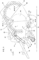
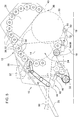
- FIG 1 shows a schematic representation of a first exemplary embodiment of the round baler 10 according to the invention
- the round baler 10 shown schematically comprises a housing 12 with a housing part 14.
- the housing 12, in particular the housing part 14, are supported on a floor 18 by means of a chassis (not shown), here in particular with wheels 16.
- the round baler can be attached to a towing vehicle (not shown), e.g. B. a tractor or agricultural tractor can be connected.
- the housing 12 also has an ejection flap 26 pivotably mounted on the housing part 14 about a bearing axis, a bearing for the pivotably mounted ejection flap 26 being located in particular on the rear upper corner region of the housing part 14.
- On the housing part 14 and the Ejection flap 26 are distributed drivable pressing means 28 which delimit a pressing chamber 24 on the circumferential side. By means of the pressing means 28, a rotation-generating or rotation-maintaining engagement effect on a round bale 30 located in the pressing chamber 24 can be generated.
- the housing part 14 thus forms a front part of the press chamber 24 and the ejection flap 26 forms a rear part of the press chamber 24.
- the ones in the Figures 1 , 4 to 5 The round balers shown can have an unloading ramp (see Figure 6 , Reference number 38).
- the round baler 10 designed with a size-invariable pressing chamber 24, contains a large number of pressing means 28 running parallel to one another for pressing crops in the form of pressing rollers 32 (only a few pressing rollers 32 have been provided with the reference symbol "32" here as an example), whose axes of rotation 34 when closed Ejection flap 26 are located on an arc, and at least some of which are driven.
- the ejection flap 26 can be actuated (opened and closed) by means of a first adjusting device (not shown).
- the ejection flap 26 can be pivoted by means of the adjusting device in such a way that when the ejection flap 26 is opened an ejection opening 36 can be formed between the housing part 14 and the ejection flap 26.
- a round bale 30 pressed by the round baler 10 can be deposited or unloaded or ejected through the ejection opening 36.
- the round bale 30 moves in the direction of the ejection opening 36 and usually rolls over the unloading ramp 38 onto the floor 18.
- the ejection flap 26 can be pivoted by means of the first adjusting device in such a way that a dimension 40 of the ejection opening, preferably a diameter of the ejection opening 36 and / or a distance between the housing part 14 and the discharge flap 26 can be changed.
- the round baler 10 also has a drive arrangement 42 with a gear arrangement 44, a first drive train 46 and a second drive train 48.
- a drive shaft 50 is connected to a power take-off shaft (not shown) Towing vehicle or tractor and serves as a drive for the drive arrangement 42.
- the first drive train 46 is drive-connected to the transmission arrangement 44 via a first output (not shown) and the second drive train 48 via a second output (not shown).
- the first drive train 46 drives the receiving and feeding device 22, the second drive train 48 being provided for driving the pressing means 28 or the pressing rollers 32.
- the drive trains 46, 48 include all drive components that are arranged in a known manner in round balers to drive the pick and feed device 22 or to drive the pressing means 28 and are connected on the drive side to the first output and the second output of the gear arrangement 44.
- the round baler 10 comprises a wrapping device 56 which is equipped with a net and / or film roll 52 as wrapping material.
- the wrapping device 56 comprises a wrapping material feed 54 which guides the wrapping material from the net or film roll 52 into the pressing chamber 24.
- a binding device (not shown) with binding twine can also be used in a known manner.
- the first and second drive trains 46, 48 are driven in parallel via the gear arrangement 44 or via the drive and the output, so that the receiving and feeding device 22 and the pressing means 28, 32 operate simultaneously with a constant speed ratio to one another being held.
- the journey over the floor 18 is interrupted because the round baler 10 is filled with the round bale 30 and no more crops can or should be taken up in the baling chamber 24 .
- the wrapping device 56 is also activated, which initiates a wrapping or binding process. In this case, the wrapping material is wrapped around the round bale 30 by continuous rotation of the round bale 30 located in the pressing chamber 24.
- the pressing process goes into the unloading process over and the round bale 30 is unloaded onto the floor 18 via the discharge opening 36 and the unloading ramp 38 by opening the outlet flap 26.
- the main problems of the known round balers 10 when unloading round bales 30, in particular round bales 30 wrapped with wrapping material, are the problems mentioned at the beginning with regard to damage to the wrapping material and the structurally and / or procedurally too complicated configuration of the round baler 10.
- the housing part 14 of the round baler 10 comprises a holding roller 60.
- the holding roller 60 is between a rest position (see FIG Figure 2 ) and a working position adjustable (see for example Figures 1 and 3 ). In the working position, the holding roller 60 assumes a position delimiting the ejection opening 36, preferably for the round bale 30 wrapped with wrapping material. It is essential for the invention that due to the inventive design of the round baler, this is structurally simpler and damage to the round bale, in particular the round bale wrapped with wrapping material, can be avoided during unloading. Due to the freely rotatable mounting, the holding roller 60 can be rotated with the round bale 30 essentially without slipping, thereby avoiding, for example, additional tensile stresses on the round bale 30 around which the wrapping material is wrapped.
- FIG. 1 shows a round baler in which the holding roller 60 is a freely rotatably mounted roller that is freely rotatably mounted on a holding roller bearing 62.
- the round baler 10 comprises a second adjusting device 64, by means of which the holding roller 60 can be adjusted between the rest position and the working position.
- the holding roller 60 is freely rotatably mounted on the second adjusting device 64 by means of the holding roller bearing 62.
- the second setting device 64 comprises a first actuator 66 which is designed as a lifting cylinder.
- the lifting cylinder can be actuated electrically, mechanically or pneumatically, for example.
- the holding roller 60 can depending on a dimension 40 of the ejection opening 36 and / or from The opening angle of the ejection flap 26 can be adjusted between the rest position and the working position.
- the holding roller 60 can be controlled by a distance sensor (not shown) which detects the dimension 40 of the ejection opening 36 and / or an angle sensor (not shown) which detects the opening angle of the discharge flap 26.
- the pressing means 28, 32, 70 of the ejection flap 26 delimiting the ejection opening 36 can be decoupled from the drive arrangement 42, for example by means of a clutch (not shown), so that the pressing means 28, 32, 70 delimiting the ejection opening 36 or the one directly connected to the Ejection opening adjoining pressing means 28, 32, 70 is freely rotatably mounted.
- the Figures 2 and 3 show a schematic top view of the holding roller 60 and the second adjusting device 64 in the rest position (see FIG Figure 2 ) and the working position (see Figure 3 ).
- the ones in the Figures 2 and 3 The holding rollers 60 shown and the second actuating devices 64 essentially correspond to that in FIG Figure 1 Holding roller 60 and the second adjusting device 64, so that only the differences will be discussed below.
- the second setting device 64 comprises the first actuator 66 and a second actuator 68.
- the second actuator 68 is also designed as a lifting cylinder which can be actuated electrically, mechanically or pneumatically, for example.
- FIG. 4 shows a schematic side view of a second exemplary embodiment of the round baler 10 according to the invention
- the round baler 10 shown corresponds essentially to that in FIG Figure 1 round baler 10 shown and the in Figure 4
- the holding roller 60 shown and the second adjusting device 64 correspond to that in FIGS Figures 2 and 3 shown holding roller 60 and the second adjusting device 64, so that only the differences will be discussed below.
- the second setting device 64 is pivotably mounted on the round baler 10, here the chassis, so that the second setting device 64 in connection with the holding roller 60 can hold and / or roll the round bale 30 to be ejected. This allows the second Adjusting device 64 in connection with holding roller 60 can advantageously be used as unloading ramp 38.
- FIG. 5 shows a schematic side view of a third exemplary embodiment of the round baler 10 according to the invention Figure 5
- the round baler 10 shown corresponds essentially to that in FIG Figure 1 and 4th round baler 10 shown and the in Figure 5
- the holding roller 60 shown and the second adjusting device 64 correspond to that in FIGS Figures 2 and 3 shown holding roller 60 and the second adjusting device 64, so that only the differences will be discussed below.
- the holding roller 60 is mounted on the first pivot lever 72 so that it can rotate freely.
- the first pivot lever 72 is mounted pivotably about an axis, so that the holding roller 60 can be pivoted between the rest position and the working position by means of the first pivot lever 72.
- the first actuator 66 is designed as a swivel cylinder.
- the swing cylinder is connected to the first swing lever 72.
- the first pivot lever 72 can be actuated and / or pivoted by means of the first actuator.
- a second pivot lever and / or a second actuator can also be provided.
- the holding roller 60 can be freely rotatably supported between the first and second pivot levers 72.
- the second actuator 68 can be connected to the second pivot lever.
- the second pivot lever can be actuated and / or pivoted by means of the second actuator 68.
- FIG. 6 shows a schematic side view of a fourth exemplary embodiment of the round baler 10 according to the invention Figure 6
- the round baler 10 shown corresponds essentially to that in FIG Figure 1 and 4 to 5 round baler 10 shown and the in Figure 6
- the holding roller 60 shown and the second adjusting device 64 correspond to that in FIGS Figures 2 and 3 shown holding roller 60 and the second adjusting device 64, so that only the differences will be discussed below.
- the holding roller 60 is mounted on the unloading ramp 38 so that it can rotate freely.
- the unloading ramp 38 as Bearings are used for the holding roller 60 and a second adjusting device 64 can be dispensed with.
Landscapes
- Life Sciences & Earth Sciences (AREA)
- Environmental Sciences (AREA)
- Storage Of Harvested Produce (AREA)
Applications Claiming Priority (1)
| Application Number | Priority Date | Filing Date | Title |
|---|---|---|---|
| DE102019209345.0A DE102019209345A1 (de) | 2019-06-27 | 2019-06-27 | Rundballenpresse und Verfahren zum Betrieb einer Rundballenpresse |
Publications (2)
| Publication Number | Publication Date |
|---|---|
| EP3760031A1 true EP3760031A1 (fr) | 2021-01-06 |
| EP3760031B1 EP3760031B1 (fr) | 2023-07-26 |
Family
ID=71138550
Family Applications (1)
| Application Number | Title | Priority Date | Filing Date |
|---|---|---|---|
| EP20181671.7A Active EP3760031B1 (fr) | 2019-06-27 | 2020-06-23 | Presse à balles rondes et procédé de fonctionnement d'une presse à balles rondes |
Country Status (3)
| Country | Link |
|---|---|
| US (1) | US11641807B2 (fr) |
| EP (1) | EP3760031B1 (fr) |
| DE (1) | DE102019209345A1 (fr) |
Families Citing this family (1)
| Publication number | Priority date | Publication date | Assignee | Title |
|---|---|---|---|---|
| DE102023108947A1 (de) * | 2023-04-06 | 2024-10-10 | Maschinenfabrik Bernard Krone GmbH & Co. KG | Rundballenpresse |
Citations (6)
| Publication number | Priority date | Publication date | Assignee | Title |
|---|---|---|---|---|
| EP1266563A1 (fr) * | 2001-06-11 | 2002-12-18 | Lely Enterprises AG | Presse à balles rondes pour des produits agricoles |
| EP1508268A1 (fr) * | 2003-08-21 | 2005-02-23 | Welger Maschinenfabrik GmbH | Presse à balles rondes |
| EP1889534A1 (fr) * | 2006-08-16 | 2008-02-20 | Deere & Company | Presse à ballots ronds |
| EP3162188A1 (fr) | 2015-10-30 | 2017-05-03 | Göweil Maschinenbau GmbH | Presse a balles rondes pour fourrage |
| EP3162187A1 (fr) | 2015-10-30 | 2017-05-03 | Göweil Maschinenbau GmbH | Presse a balles rondes pour fourrage |
| EP3165079A1 (fr) * | 2015-11-06 | 2017-05-10 | Göweil Maschinenbau GmbH | Presse à balles rondes |
Family Cites Families (1)
| Publication number | Priority date | Publication date | Assignee | Title |
|---|---|---|---|---|
| DE102004022801A1 (de) * | 2004-05-08 | 2005-12-15 | Deere & Company, Moline | Rundballenpresse |
-
2019
- 2019-06-27 DE DE102019209345.0A patent/DE102019209345A1/de not_active Withdrawn
-
2020
- 2020-04-23 US US16/856,238 patent/US11641807B2/en active Active
- 2020-06-23 EP EP20181671.7A patent/EP3760031B1/fr active Active
Patent Citations (6)
| Publication number | Priority date | Publication date | Assignee | Title |
|---|---|---|---|---|
| EP1266563A1 (fr) * | 2001-06-11 | 2002-12-18 | Lely Enterprises AG | Presse à balles rondes pour des produits agricoles |
| EP1508268A1 (fr) * | 2003-08-21 | 2005-02-23 | Welger Maschinenfabrik GmbH | Presse à balles rondes |
| EP1889534A1 (fr) * | 2006-08-16 | 2008-02-20 | Deere & Company | Presse à ballots ronds |
| EP3162188A1 (fr) | 2015-10-30 | 2017-05-03 | Göweil Maschinenbau GmbH | Presse a balles rondes pour fourrage |
| EP3162187A1 (fr) | 2015-10-30 | 2017-05-03 | Göweil Maschinenbau GmbH | Presse a balles rondes pour fourrage |
| EP3165079A1 (fr) * | 2015-11-06 | 2017-05-10 | Göweil Maschinenbau GmbH | Presse à balles rondes |
Also Published As
| Publication number | Publication date |
|---|---|
| EP3760031B1 (fr) | 2023-07-26 |
| US11641807B2 (en) | 2023-05-09 |
| DE102019209345A1 (de) | 2020-12-31 |
| US20200404853A1 (en) | 2020-12-31 |
Similar Documents
| Publication | Publication Date | Title |
|---|---|---|
| EP1593299B1 (fr) | Presse à balles rondes | |
| DE69607969T4 (de) | Rundballenpresse mit veränderlichem pressraum und ein pressraum mit veränderlicher geometrie um ballenkerne zu formen | |
| EP3721699B1 (fr) | Dispositif d'enroulement de balles pour une presse à balles, aide au chargement et presse à balles | |
| EP3578035B1 (fr) | Presse à balles rondes et procédé de déchargement | |
| EP4272541A1 (fr) | Combinaison et procédé de fonctionnement d'une combinaison | |
| EP2878190B1 (fr) | Presse à balles rondes agricole | |
| EP2893799A1 (fr) | Presse à balles rondes agricole et procédé | |
| EP1230837B1 (fr) | Presse à balles rondes | |
| DE102015211035A1 (de) | Rundballenpresse mit einem Sensor zur Erfassung der Ballengröße | |
| EP3900517A1 (fr) | Presse à balles rondes et procédé de fonctionnement d'une presse à balles rondes | |
| EP4430942A1 (fr) | Combinaison, procédé de fonctionnement d'une combinaison et presse à balles | |
| EP3760031B1 (fr) | Presse à balles rondes et procédé de fonctionnement d'une presse à balles rondes | |
| EP3560323B1 (fr) | Presse à balles rondes et procédé de fonctionnement d'une presse à balles rondes | |
| EP1048202B1 (fr) | Bobineuse à emballer | |
| DE29911916U1 (de) | Wickelvorrichtung und System zum Pressen und Wickeln von Ballen | |
| EP3106021B1 (fr) | Presse à balles rondes | |
| EP2042027A1 (fr) | Presse à ballots ronds | |
| EP4272542A1 (fr) | Combinaison et procédé de fonctionnement d'une combinaison | |
| DE102022111005A1 (de) | Kombination und Verfahren zum Betreiben einer Kombination | |
| EP4176705A1 (fr) | Presse à balles rondes avec un dispositif pour serrer une balle | |
| EP4466977A2 (fr) | Presse à balles pour récolte agricole | |
| EP2853145B1 (fr) | Presse à balles rondes | |
| DE102015115709A1 (de) | Rundballenpresse | |
| EP3103324B1 (fr) | Presse agricole à balles rondes | |
| EP3560322B1 (fr) | Presse à balles rondes |
Legal Events
| Date | Code | Title | Description |
|---|---|---|---|
| PUAI | Public reference made under article 153(3) epc to a published international application that has entered the european phase |
Free format text: ORIGINAL CODE: 0009012 |
|
| STAA | Information on the status of an ep patent application or granted ep patent |
Free format text: STATUS: THE APPLICATION HAS BEEN PUBLISHED |
|
| AK | Designated contracting states |
Kind code of ref document: A1 Designated state(s): AL AT BE BG CH CY CZ DE DK EE ES FI FR GB GR HR HU IE IS IT LI LT LU LV MC MK MT NL NO PL PT RO RS SE SI SK SM TR |
|
| AX | Request for extension of the european patent |
Extension state: BA ME |
|
| STAA | Information on the status of an ep patent application or granted ep patent |
Free format text: STATUS: REQUEST FOR EXAMINATION WAS MADE |
|
| 17P | Request for examination filed |
Effective date: 20210706 |
|
| RBV | Designated contracting states (corrected) |
Designated state(s): AL AT BE BG CH CY CZ DE DK EE ES FI FR GB GR HR HU IE IS IT LI LT LU LV MC MK MT NL NO PL PT RO RS SE SI SK SM TR |
|
| GRAP | Despatch of communication of intention to grant a patent |
Free format text: ORIGINAL CODE: EPIDOSNIGR1 |
|
| STAA | Information on the status of an ep patent application or granted ep patent |
Free format text: STATUS: GRANT OF PATENT IS INTENDED |
|
| INTG | Intention to grant announced |
Effective date: 20230301 |
|
| GRAS | Grant fee paid |
Free format text: ORIGINAL CODE: EPIDOSNIGR3 |
|
| GRAA | (expected) grant |
Free format text: ORIGINAL CODE: 0009210 |
|
| STAA | Information on the status of an ep patent application or granted ep patent |
Free format text: STATUS: THE PATENT HAS BEEN GRANTED |
|
| AK | Designated contracting states |
Kind code of ref document: B1 Designated state(s): AL AT BE BG CH CY CZ DE DK EE ES FI FR GB GR HR HU IE IS IT LI LT LU LV MC MK MT NL NO PL PT RO RS SE SI SK SM TR |
|
| REG | Reference to a national code |
Ref country code: CH Ref legal event code: EP |
|
| REG | Reference to a national code |
Ref country code: IE Ref legal event code: FG4D Free format text: LANGUAGE OF EP DOCUMENT: GERMAN |
|
| REG | Reference to a national code |
Ref country code: DE Ref legal event code: R096 Ref document number: 502020004340 Country of ref document: DE |
|
| REG | Reference to a national code |
Ref country code: LT Ref legal event code: MG9D |
|
| REG | Reference to a national code |
Ref country code: NL Ref legal event code: MP Effective date: 20230726 |
|
| PG25 | Lapsed in a contracting state [announced via postgrant information from national office to epo] |
Ref country code: NL Free format text: LAPSE BECAUSE OF FAILURE TO SUBMIT A TRANSLATION OF THE DESCRIPTION OR TO PAY THE FEE WITHIN THE PRESCRIBED TIME-LIMIT Effective date: 20230726 |
|
| PG25 | Lapsed in a contracting state [announced via postgrant information from national office to epo] |
Ref country code: GR Free format text: LAPSE BECAUSE OF FAILURE TO SUBMIT A TRANSLATION OF THE DESCRIPTION OR TO PAY THE FEE WITHIN THE PRESCRIBED TIME-LIMIT Effective date: 20231027 |
|
| PG25 | Lapsed in a contracting state [announced via postgrant information from national office to epo] |
Ref country code: IS Free format text: LAPSE BECAUSE OF FAILURE TO SUBMIT A TRANSLATION OF THE DESCRIPTION OR TO PAY THE FEE WITHIN THE PRESCRIBED TIME-LIMIT Effective date: 20231126 |
|
| PG25 | Lapsed in a contracting state [announced via postgrant information from national office to epo] |
Ref country code: SE Free format text: LAPSE BECAUSE OF FAILURE TO SUBMIT A TRANSLATION OF THE DESCRIPTION OR TO PAY THE FEE WITHIN THE PRESCRIBED TIME-LIMIT Effective date: 20230726 Ref country code: RS Free format text: LAPSE BECAUSE OF FAILURE TO SUBMIT A TRANSLATION OF THE DESCRIPTION OR TO PAY THE FEE WITHIN THE PRESCRIBED TIME-LIMIT Effective date: 20230726 Ref country code: PT Free format text: LAPSE BECAUSE OF FAILURE TO SUBMIT A TRANSLATION OF THE DESCRIPTION OR TO PAY THE FEE WITHIN THE PRESCRIBED TIME-LIMIT Effective date: 20231127 Ref country code: NO Free format text: LAPSE BECAUSE OF FAILURE TO SUBMIT A TRANSLATION OF THE DESCRIPTION OR TO PAY THE FEE WITHIN THE PRESCRIBED TIME-LIMIT Effective date: 20231026 Ref country code: LV Free format text: LAPSE BECAUSE OF FAILURE TO SUBMIT A TRANSLATION OF THE DESCRIPTION OR TO PAY THE FEE WITHIN THE PRESCRIBED TIME-LIMIT Effective date: 20230726 Ref country code: LT Free format text: LAPSE BECAUSE OF FAILURE TO SUBMIT A TRANSLATION OF THE DESCRIPTION OR TO PAY THE FEE WITHIN THE PRESCRIBED TIME-LIMIT Effective date: 20230726 Ref country code: IS Free format text: LAPSE BECAUSE OF FAILURE TO SUBMIT A TRANSLATION OF THE DESCRIPTION OR TO PAY THE FEE WITHIN THE PRESCRIBED TIME-LIMIT Effective date: 20231126 Ref country code: HR Free format text: LAPSE BECAUSE OF FAILURE TO SUBMIT A TRANSLATION OF THE DESCRIPTION OR TO PAY THE FEE WITHIN THE PRESCRIBED TIME-LIMIT Effective date: 20230726 Ref country code: GR Free format text: LAPSE BECAUSE OF FAILURE TO SUBMIT A TRANSLATION OF THE DESCRIPTION OR TO PAY THE FEE WITHIN THE PRESCRIBED TIME-LIMIT Effective date: 20231027 Ref country code: FI Free format text: LAPSE BECAUSE OF FAILURE TO SUBMIT A TRANSLATION OF THE DESCRIPTION OR TO PAY THE FEE WITHIN THE PRESCRIBED TIME-LIMIT Effective date: 20230726 |
|
| PG25 | Lapsed in a contracting state [announced via postgrant information from national office to epo] |
Ref country code: PL Free format text: LAPSE BECAUSE OF FAILURE TO SUBMIT A TRANSLATION OF THE DESCRIPTION OR TO PAY THE FEE WITHIN THE PRESCRIBED TIME-LIMIT Effective date: 20230726 |
|
| PG25 | Lapsed in a contracting state [announced via postgrant information from national office to epo] |
Ref country code: ES Free format text: LAPSE BECAUSE OF FAILURE TO SUBMIT A TRANSLATION OF THE DESCRIPTION OR TO PAY THE FEE WITHIN THE PRESCRIBED TIME-LIMIT Effective date: 20230726 |
|
| REG | Reference to a national code |
Ref country code: DE Ref legal event code: R097 Ref document number: 502020004340 Country of ref document: DE |
|
| PG25 | Lapsed in a contracting state [announced via postgrant information from national office to epo] |
Ref country code: SM Free format text: LAPSE BECAUSE OF FAILURE TO SUBMIT A TRANSLATION OF THE DESCRIPTION OR TO PAY THE FEE WITHIN THE PRESCRIBED TIME-LIMIT Effective date: 20230726 Ref country code: RO Free format text: LAPSE BECAUSE OF FAILURE TO SUBMIT A TRANSLATION OF THE DESCRIPTION OR TO PAY THE FEE WITHIN THE PRESCRIBED TIME-LIMIT Effective date: 20230726 Ref country code: ES Free format text: LAPSE BECAUSE OF FAILURE TO SUBMIT A TRANSLATION OF THE DESCRIPTION OR TO PAY THE FEE WITHIN THE PRESCRIBED TIME-LIMIT Effective date: 20230726 Ref country code: EE Free format text: LAPSE BECAUSE OF FAILURE TO SUBMIT A TRANSLATION OF THE DESCRIPTION OR TO PAY THE FEE WITHIN THE PRESCRIBED TIME-LIMIT Effective date: 20230726 Ref country code: DK Free format text: LAPSE BECAUSE OF FAILURE TO SUBMIT A TRANSLATION OF THE DESCRIPTION OR TO PAY THE FEE WITHIN THE PRESCRIBED TIME-LIMIT Effective date: 20230726 Ref country code: CZ Free format text: LAPSE BECAUSE OF FAILURE TO SUBMIT A TRANSLATION OF THE DESCRIPTION OR TO PAY THE FEE WITHIN THE PRESCRIBED TIME-LIMIT Effective date: 20230726 Ref country code: SK Free format text: LAPSE BECAUSE OF FAILURE TO SUBMIT A TRANSLATION OF THE DESCRIPTION OR TO PAY THE FEE WITHIN THE PRESCRIBED TIME-LIMIT Effective date: 20230726 |
|
| PG25 | Lapsed in a contracting state [announced via postgrant information from national office to epo] |
Ref country code: IT Free format text: LAPSE BECAUSE OF FAILURE TO SUBMIT A TRANSLATION OF THE DESCRIPTION OR TO PAY THE FEE WITHIN THE PRESCRIBED TIME-LIMIT Effective date: 20230726 |
|
| PLBE | No opposition filed within time limit |
Free format text: ORIGINAL CODE: 0009261 |
|
| STAA | Information on the status of an ep patent application or granted ep patent |
Free format text: STATUS: NO OPPOSITION FILED WITHIN TIME LIMIT |
|
| 26N | No opposition filed |
Effective date: 20240429 |
|
| PG25 | Lapsed in a contracting state [announced via postgrant information from national office to epo] |
Ref country code: SI Free format text: LAPSE BECAUSE OF FAILURE TO SUBMIT A TRANSLATION OF THE DESCRIPTION OR TO PAY THE FEE WITHIN THE PRESCRIBED TIME-LIMIT Effective date: 20230726 |
|
| PG25 | Lapsed in a contracting state [announced via postgrant information from national office to epo] |
Ref country code: BG Free format text: LAPSE BECAUSE OF FAILURE TO SUBMIT A TRANSLATION OF THE DESCRIPTION OR TO PAY THE FEE WITHIN THE PRESCRIBED TIME-LIMIT Effective date: 20230726 |
|
| PG25 | Lapsed in a contracting state [announced via postgrant information from national office to epo] |
Ref country code: BG Free format text: LAPSE BECAUSE OF FAILURE TO SUBMIT A TRANSLATION OF THE DESCRIPTION OR TO PAY THE FEE WITHIN THE PRESCRIBED TIME-LIMIT Effective date: 20230726 |
|
| PG25 | Lapsed in a contracting state [announced via postgrant information from national office to epo] |
Ref country code: MC Free format text: LAPSE BECAUSE OF FAILURE TO SUBMIT A TRANSLATION OF THE DESCRIPTION OR TO PAY THE FEE WITHIN THE PRESCRIBED TIME-LIMIT Effective date: 20230726 |
|
| REG | Reference to a national code |
Ref country code: CH Ref legal event code: PL |
|
| PG25 | Lapsed in a contracting state [announced via postgrant information from national office to epo] |
Ref country code: LU Free format text: LAPSE BECAUSE OF NON-PAYMENT OF DUE FEES Effective date: 20240623 |
|
| GBPC | Gb: european patent ceased through non-payment of renewal fee |
Effective date: 20240623 |
|
| PG25 | Lapsed in a contracting state [announced via postgrant information from national office to epo] |
Ref country code: IE Free format text: LAPSE BECAUSE OF NON-PAYMENT OF DUE FEES Effective date: 20240623 |
|
| PG25 | Lapsed in a contracting state [announced via postgrant information from national office to epo] |
Ref country code: CH Free format text: LAPSE BECAUSE OF NON-PAYMENT OF DUE FEES Effective date: 20240630 Ref country code: BE Free format text: LAPSE BECAUSE OF NON-PAYMENT OF DUE FEES Effective date: 20240630 |
|
| PG25 | Lapsed in a contracting state [announced via postgrant information from national office to epo] |
Ref country code: GB Free format text: LAPSE BECAUSE OF NON-PAYMENT OF DUE FEES Effective date: 20240623 |
|
| REG | Reference to a national code |
Ref country code: BE Ref legal event code: MM Effective date: 20240630 |
|
| PGFP | Annual fee paid to national office [announced via postgrant information from national office to epo] |
Ref country code: DE Payment date: 20250521 Year of fee payment: 6 |
|
| PGFP | Annual fee paid to national office [announced via postgrant information from national office to epo] |
Ref country code: FR Payment date: 20250625 Year of fee payment: 6 |
|
| PGFP | Annual fee paid to national office [announced via postgrant information from national office to epo] |
Ref country code: AT Payment date: 20250721 Year of fee payment: 5 |
|
| PG25 | Lapsed in a contracting state [announced via postgrant information from national office to epo] |
Ref country code: CY Free format text: LAPSE BECAUSE OF FAILURE TO SUBMIT A TRANSLATION OF THE DESCRIPTION OR TO PAY THE FEE WITHIN THE PRESCRIBED TIME-LIMIT; INVALID AB INITIO Effective date: 20200623 |
|
| PG25 | Lapsed in a contracting state [announced via postgrant information from national office to epo] |
Ref country code: HU Free format text: LAPSE BECAUSE OF FAILURE TO SUBMIT A TRANSLATION OF THE DESCRIPTION OR TO PAY THE FEE WITHIN THE PRESCRIBED TIME-LIMIT; INVALID AB INITIO Effective date: 20200623 |