EP1508437A2 - Gehäuse mit Sandwichstruktur und Verfahren zur Herstellung - Google Patents
Gehäuse mit Sandwichstruktur und Verfahren zur Herstellung Download PDFInfo
- Publication number
- EP1508437A2 EP1508437A2 EP04077311A EP04077311A EP1508437A2 EP 1508437 A2 EP1508437 A2 EP 1508437A2 EP 04077311 A EP04077311 A EP 04077311A EP 04077311 A EP04077311 A EP 04077311A EP 1508437 A2 EP1508437 A2 EP 1508437A2
- Authority
- EP
- European Patent Office
- Prior art keywords
- wall
- reinforcing elements
- walls
- housing
- foregoing
- Prior art date
- Legal status (The legal status is an assumption and is not a legal conclusion. Google has not performed a legal analysis and makes no representation as to the accuracy of the status listed.)
- Granted
Links
- 238000004519 manufacturing process Methods 0.000 title claims description 19
- 230000003014 reinforcing effect Effects 0.000 claims abstract description 67
- 238000010276 construction Methods 0.000 claims abstract description 26
- 239000012530 fluid Substances 0.000 claims abstract description 15
- 239000000463 material Substances 0.000 claims description 36
- 238000000034 method Methods 0.000 claims description 30
- 239000000945 filler Substances 0.000 claims description 25
- 229920002635 polyurethane Polymers 0.000 claims description 25
- 239000004814 polyurethane Substances 0.000 claims description 25
- 239000004698 Polyethylene Substances 0.000 claims description 17
- 229920000573 polyethylene Polymers 0.000 claims description 12
- -1 polyethylene Polymers 0.000 claims description 10
- 239000012815 thermoplastic material Substances 0.000 claims description 9
- 238000001816 cooling Methods 0.000 claims description 7
- 238000002844 melting Methods 0.000 claims description 7
- 230000008018 melting Effects 0.000 claims description 7
- 238000010438 heat treatment Methods 0.000 claims description 6
- 239000002245 particle Substances 0.000 claims description 2
- 239000006260 foam Substances 0.000 description 19
- 229920003023 plastic Polymers 0.000 description 14
- 239000004033 plastic Substances 0.000 description 14
- 238000000465 moulding Methods 0.000 description 6
- 230000000694 effects Effects 0.000 description 4
- 239000007789 gas Substances 0.000 description 4
- 239000000843 powder Substances 0.000 description 4
- 239000008187 granular material Substances 0.000 description 3
- 230000002787 reinforcement Effects 0.000 description 3
- 239000002699 waste material Substances 0.000 description 3
- 239000004604 Blowing Agent Substances 0.000 description 2
- 239000003570 air Substances 0.000 description 2
- 230000008602 contraction Effects 0.000 description 2
- 239000011796 hollow space material Substances 0.000 description 2
- 239000007788 liquid Substances 0.000 description 2
- 239000000203 mixture Substances 0.000 description 2
- 238000003672 processing method Methods 0.000 description 2
- 238000005070 sampling Methods 0.000 description 2
- 229920001169 thermoplastic Polymers 0.000 description 2
- 239000004416 thermosoftening plastic Substances 0.000 description 2
- 238000009827 uniform distribution Methods 0.000 description 2
- 239000002351 wastewater Substances 0.000 description 2
- XLYOFNOQVPJJNP-UHFFFAOYSA-N water Substances O XLYOFNOQVPJJNP-UHFFFAOYSA-N 0.000 description 2
- 230000002411 adverse Effects 0.000 description 1
- 239000012080 ambient air Substances 0.000 description 1
- 238000004458 analytical method Methods 0.000 description 1
- 230000009172 bursting Effects 0.000 description 1
- 238000011109 contamination Methods 0.000 description 1
- 230000001066 destructive effect Effects 0.000 description 1
- 238000000605 extraction Methods 0.000 description 1
- 238000011010 flushing procedure Methods 0.000 description 1
- 238000005187 foaming Methods 0.000 description 1
- 239000007792 gaseous phase Substances 0.000 description 1
- 230000005484 gravity Effects 0.000 description 1
- 239000010842 industrial wastewater Substances 0.000 description 1
- 238000009413 insulation Methods 0.000 description 1
- 239000012948 isocyanate Substances 0.000 description 1
- 150000002513 isocyanates Chemical class 0.000 description 1
- 239000010410 layer Substances 0.000 description 1
- 238000012986 modification Methods 0.000 description 1
- 230000004048 modification Effects 0.000 description 1
- 238000012544 monitoring process Methods 0.000 description 1
- 239000012071 phase Substances 0.000 description 1
- 229920005862 polyol Polymers 0.000 description 1
- 150000003077 polyols Chemical class 0.000 description 1
- 238000012545 processing Methods 0.000 description 1
- 239000007787 solid Substances 0.000 description 1
- 239000002344 surface layer Substances 0.000 description 1
- 238000013022 venting Methods 0.000 description 1
Images


Classifications
-
- B—PERFORMING OPERATIONS; TRANSPORTING
- B32—LAYERED PRODUCTS
- B32B—LAYERED PRODUCTS, i.e. PRODUCTS BUILT-UP OF STRATA OF FLAT OR NON-FLAT, e.g. CELLULAR OR HONEYCOMB, FORM
- B32B27/00—Layered products comprising a layer of synthetic resin
- B32B27/06—Layered products comprising a layer of synthetic resin as the main or only constituent of a layer, which is next to another layer of the same or of a different material
- B32B27/065—Layered products comprising a layer of synthetic resin as the main or only constituent of a layer, which is next to another layer of the same or of a different material of foam
-
- A—HUMAN NECESSITIES
- A47—FURNITURE; DOMESTIC ARTICLES OR APPLIANCES; COFFEE MILLS; SPICE MILLS; SUCTION CLEANERS IN GENERAL
- A47B—TABLES; DESKS; OFFICE FURNITURE; CABINETS; DRAWERS; GENERAL DETAILS OF FURNITURE
- A47B47/00—Cabinets, racks or shelf units, characterised by features related to dismountability or building-up from elements
-
- A—HUMAN NECESSITIES
- A47—FURNITURE; DOMESTIC ARTICLES OR APPLIANCES; COFFEE MILLS; SPICE MILLS; SUCTION CLEANERS IN GENERAL
- A47B—TABLES; DESKS; OFFICE FURNITURE; CABINETS; DRAWERS; GENERAL DETAILS OF FURNITURE
- A47B96/00—Details of cabinets, racks or shelf units not covered by a single one of groups A47B43/00 - A47B95/00; General details of furniture
- A47B96/20—Furniture panels or like furniture elements
- A47B96/205—Composite panels, comprising several elements joined together
- A47B96/206—Composite panels, comprising several elements joined together with laminates comprising planar, continuous or separate layers
-
- B—PERFORMING OPERATIONS; TRANSPORTING
- B01—PHYSICAL OR CHEMICAL PROCESSES OR APPARATUS IN GENERAL
- B01L—CHEMICAL OR PHYSICAL LABORATORY APPARATUS FOR GENERAL USE
- B01L1/00—Enclosures; Chambers
-
- B—PERFORMING OPERATIONS; TRANSPORTING
- B29—WORKING OF PLASTICS; WORKING OF SUBSTANCES IN A PLASTIC STATE IN GENERAL
- B29C—SHAPING OR JOINING OF PLASTICS; SHAPING OF MATERIAL IN A PLASTIC STATE, NOT OTHERWISE PROVIDED FOR; AFTER-TREATMENT OF THE SHAPED PRODUCTS, e.g. REPAIRING
- B29C37/00—Component parts, details, accessories or auxiliary operations, not covered by group B29C33/00 or B29C35/00
- B29C37/0078—Measures or configurations for obtaining anchoring effects in the contact areas between layers
- B29C37/0082—Mechanical anchoring
-
- B—PERFORMING OPERATIONS; TRANSPORTING
- B29—WORKING OF PLASTICS; WORKING OF SUBSTANCES IN A PLASTIC STATE IN GENERAL
- B29C—SHAPING OR JOINING OF PLASTICS; SHAPING OF MATERIAL IN A PLASTIC STATE, NOT OTHERWISE PROVIDED FOR; AFTER-TREATMENT OF THE SHAPED PRODUCTS, e.g. REPAIRING
- B29C44/00—Shaping by internal pressure generated in the material, e.g. swelling or foaming ; Producing porous or cellular expanded plastics articles
- B29C44/02—Shaping by internal pressure generated in the material, e.g. swelling or foaming ; Producing porous or cellular expanded plastics articles for articles of definite length, i.e. discrete articles
- B29C44/04—Shaping by internal pressure generated in the material, e.g. swelling or foaming ; Producing porous or cellular expanded plastics articles for articles of definite length, i.e. discrete articles consisting of at least two parts of chemically or physically different materials, e.g. having different densities
- B29C44/0461—Shaping by internal pressure generated in the material, e.g. swelling or foaming ; Producing porous or cellular expanded plastics articles for articles of definite length, i.e. discrete articles consisting of at least two parts of chemically or physically different materials, e.g. having different densities by having different chemical compositions in different places, e.g. having different concentrations of foaming agent, feeding one composition after the other
-
- B—PERFORMING OPERATIONS; TRANSPORTING
- B29—WORKING OF PLASTICS; WORKING OF SUBSTANCES IN A PLASTIC STATE IN GENERAL
- B29C—SHAPING OR JOINING OF PLASTICS; SHAPING OF MATERIAL IN A PLASTIC STATE, NOT OTHERWISE PROVIDED FOR; AFTER-TREATMENT OF THE SHAPED PRODUCTS, e.g. REPAIRING
- B29C44/00—Shaping by internal pressure generated in the material, e.g. swelling or foaming ; Producing porous or cellular expanded plastics articles
- B29C44/02—Shaping by internal pressure generated in the material, e.g. swelling or foaming ; Producing porous or cellular expanded plastics articles for articles of definite length, i.e. discrete articles
- B29C44/12—Incorporating or moulding on preformed parts, e.g. inserts or reinforcements
- B29C44/18—Filling preformed cavities
-
- B—PERFORMING OPERATIONS; TRANSPORTING
- B32—LAYERED PRODUCTS
- B32B—LAYERED PRODUCTS, i.e. PRODUCTS BUILT-UP OF STRATA OF FLAT OR NON-FLAT, e.g. CELLULAR OR HONEYCOMB, FORM
- B32B27/00—Layered products comprising a layer of synthetic resin
- B32B27/40—Layered products comprising a layer of synthetic resin comprising polyurethanes
-
- B—PERFORMING OPERATIONS; TRANSPORTING
- B32—LAYERED PRODUCTS
- B32B—LAYERED PRODUCTS, i.e. PRODUCTS BUILT-UP OF STRATA OF FLAT OR NON-FLAT, e.g. CELLULAR OR HONEYCOMB, FORM
- B32B3/00—Layered products comprising a layer with external or internal discontinuities or unevennesses, or a layer of non-planar shape; Layered products comprising a layer having particular features of form
- B32B3/02—Layered products comprising a layer with external or internal discontinuities or unevennesses, or a layer of non-planar shape; Layered products comprising a layer having particular features of form characterised by features of form at particular places, e.g. in edge regions
- B32B3/04—Layered products comprising a layer with external or internal discontinuities or unevennesses, or a layer of non-planar shape; Layered products comprising a layer having particular features of form characterised by features of form at particular places, e.g. in edge regions characterised by at least one layer folded at the edge, e.g. over another layer ; characterised by at least one layer enveloping or enclosing a material
-
- B—PERFORMING OPERATIONS; TRANSPORTING
- B32—LAYERED PRODUCTS
- B32B—LAYERED PRODUCTS, i.e. PRODUCTS BUILT-UP OF STRATA OF FLAT OR NON-FLAT, e.g. CELLULAR OR HONEYCOMB, FORM
- B32B5/00—Layered products characterised by the non- homogeneity or physical structure, i.e. comprising a fibrous, filamentary, particulate or foam layer; Layered products characterised by having a layer differing constitutionally or physically in different parts
- B32B5/18—Layered products characterised by the non- homogeneity or physical structure, i.e. comprising a fibrous, filamentary, particulate or foam layer; Layered products characterised by having a layer differing constitutionally or physically in different parts characterised by features of a layer of foamed material
-
- B—PERFORMING OPERATIONS; TRANSPORTING
- B32—LAYERED PRODUCTS
- B32B—LAYERED PRODUCTS, i.e. PRODUCTS BUILT-UP OF STRATA OF FLAT OR NON-FLAT, e.g. CELLULAR OR HONEYCOMB, FORM
- B32B7/00—Layered products characterised by the relation between layers; Layered products characterised by the relative orientation of features between layers, or by the relative values of a measurable parameter between layers, i.e. products comprising layers having different physical, chemical or physicochemical properties; Layered products characterised by the interconnection of layers
-
- G—PHYSICS
- G01—MEASURING; TESTING
- G01N—INVESTIGATING OR ANALYSING MATERIALS BY DETERMINING THEIR CHEMICAL OR PHYSICAL PROPERTIES
- G01N1/00—Sampling; Preparing specimens for investigation
- G01N1/02—Devices for withdrawing samples
- G01N1/10—Devices for withdrawing samples in the liquid or fluent state
-
- B—PERFORMING OPERATIONS; TRANSPORTING
- B01—PHYSICAL OR CHEMICAL PROCESSES OR APPARATUS IN GENERAL
- B01L—CHEMICAL OR PHYSICAL LABORATORY APPARATUS FOR GENERAL USE
- B01L2300/00—Additional constructional details
- B01L2300/18—Means for temperature control
- B01L2300/1883—Means for temperature control using thermal insulation
-
- B—PERFORMING OPERATIONS; TRANSPORTING
- B29—WORKING OF PLASTICS; WORKING OF SUBSTANCES IN A PLASTIC STATE IN GENERAL
- B29K—INDEXING SCHEME ASSOCIATED WITH SUBCLASSES B29B, B29C OR B29D, RELATING TO MOULDING MATERIALS OR TO MATERIALS FOR MOULDS, REINFORCEMENTS, FILLERS OR PREFORMED PARTS, e.g. INSERTS
- B29K2023/00—Use of polyalkenes or derivatives thereof as moulding material
- B29K2023/04—Polymers of ethylene
- B29K2023/06—PE, i.e. polyethylene
-
- B—PERFORMING OPERATIONS; TRANSPORTING
- B29—WORKING OF PLASTICS; WORKING OF SUBSTANCES IN A PLASTIC STATE IN GENERAL
- B29K—INDEXING SCHEME ASSOCIATED WITH SUBCLASSES B29B, B29C OR B29D, RELATING TO MOULDING MATERIALS OR TO MATERIALS FOR MOULDS, REINFORCEMENTS, FILLERS OR PREFORMED PARTS, e.g. INSERTS
- B29K2075/00—Use of PU, i.e. polyureas or polyurethanes or derivatives thereof, as moulding material
Definitions
- the present invention relates to a housing generally and to a housing for holding a fluid sampler in particular.
- the invention also relates to a method for manufacturing a sandwich wall construction generally and a sandwich wall construction for said housing in particular.
- sampler for monitoring the quality of industrial wastewater. These samplers take samples periodically or continuously from industrial or other waste flows, such as wastewater or residual gases. Many per se known techniques can be applied for taking a sample. The choice of technique here depends partly on the degree and type of contamination of the waste flow. Use can for instance be made of vacuum suction equipment in sampling open channels, while for extraction from closed conduits use is for instance made of flushing systems. Such samplers are usually arranged outside in housings specially intended for the purpose.
- the housings are often arranged in the outside air, they are subject to the influences of highly variable weather conditions.
- the housing must therefore be able to withstand ambient air temperatures varying between about -20°C and +40°C. Due to solar insolation however, the temperature of the housing can nevertheless rise above 40°C. In some applications the samples taken must furthermore be stored at a relatively low ambient temperature.
- a cooling system is therefore arranged in such housings which ensures that the temperature within the housing is held at a value of about 2 to 5°C.
- Housings which are manufactured from a sandwich construction consisting of two polyethylene sheets with a core of polyurethane (PUR) therebetween.
- PUR polyurethane
- It a further object of the invention to provide a method for manufacturing a housing assembled from a sandwich wall construction.
- a housing comprising a number of walls which define an inner space in which an apparatus such as a fluid sampler can be placed, wherein each of the walls is manufactured from a sandwich construction consisting of a core to which are fixed an inner wall, which adjoins the internal space, and an outer wall wherein reinforcing elements are arranged against the inner surface of the outer wall connecting onto the core such that they extend some distance from the inner surface into the core for the purpose of increasing the adhesion between the core and the outer wall.
- the invention is based on the insight that, in order to make the housing better able to withstand changing ambient temperatures, the adhesion between particularly the outer wall of the housing and the core of the sandwich construction must be improved.
- a number of reinforcing elements are arranged according to the invention against the inner surface of the outer wall.
- the reinforcing elements extend into the core of the sandwich construction connecting onto the inner surface.
- the consequence hereof is that the core and the outer wall no longer become detached from each other, or at least do so less easily. This results in a greatly increased lifespan of the housing, which results in a saving not only of manufacturing costs but also of labour costs for erecting the housing.
- the housing comprises one or more upright side walls, an upper wall and a lower wall, wherein the inner walls and the outer walls of the side walls, the upper wall and/or the lower wall are formed integrally.
- reinforcing elements are also arranged against the inner surface of the inner wall connecting to the core for the purpose of increasing the adhesion between the core and the inner wall.
- the core is fixed on one side to the inner surface of the outer wall and to the reinforcing elements and the core is fixed on the other side only against the inner surface of the inner wall. This situation occurs particularly when the temperature inside the housing varies little, for instance because a temperature control system (a cooling and/or heating) is arranged inside the housing. Such a situation produces less destructive forces in the housing than the above mentioned situation, and an improved adhesion between the core and the inner wall can be dispensed with.
- a cooling system is arranged in the housing for holding the internal temperature in the housing at an almost constant value between 2 and 10°C, and preferably between 2 and 5°C at a temperature varying between -20 and +40°C outside the housing. In this manner a correct and reproducible sampling and optional analysis of the waste flow is ensured.
- the invention comprises connecting means extending through the sandwich construction for connecting a fluid feed to a fluid sampler placed in the housing.
- the fluid (i.e. liquid and/or gas) feed is arranged through the sandwich construction and debouches in a fluid sampler which can take samples of the supplied fluid at set times or continuously.
- the walls are preferably manufactured from plastic, for instance from polyethylene.
- Polyethylene can likewise be used per se as filler material for the core, but in a further preferred embodiment of the invention PUR (polyurethane) is however applied.
- PUR polyurethane
- the filler material not only has the function of providing the sandwich construction itself with structural strength, but also has a heat-insulating effect.
- the PUR foam has thermal expansion characteristics which differ from those of the plastic walls. This means that as temperatures vary the different components of the sandwich construction, i.e. the inner wall, the core and the outer wall, will contract or expand in differing measures.
- reinforcing elements are arranged as set forth above on the inner surface of the relevant wall. This arranging can take place by fixedly adhering the reinforcing elements to the relevant inner surface of the wall. Preferably however, the inner surface of the relevant wall is heated such that it softens, whereafter the reinforcing elements can be arranged in the surface layer of the wall that has become soft. A firm attachment of the reinforcing elements to the relevant wall is hereby effected after cooling.
- the material from which the reinforcing elements are manufactured has a melting temperature which is practically equal to that of the material of the wall itself. This means that upon heating both the wall and the reinforcing elements become soft, so that an extremely good attachment of the reinforcing elements to the relevant surface can be ensured.
- a reinforcing element has an elongate form, at least one end of which is fixed in the boundary layer of the wall. This means that the other end of the reinforcing element in question extends as far as possible from the inner surface of the wall, which provides an improved gripping of the reinforcement on the core, with the result that an improved adhesion can be realized between the wall and the core.
- the reinforcing elements have a length preferably amounting to between 0.5 cm and 4 cm, and more preferably to between 1 and 2 cm. An optimum adhesion can hereby be achieved without the dimensions of the reinforcing elements having an adverse effect on the production process. In the case of reinforcing elements with dimensions which are too large it is for instance difficult or impossible to spread the reinforcing elements evenly over the inner surfaces of the walls. Furthermore, when a rotation process is used the rotation moulding machine can become jammed.
- a method for manufacturing a housing consisting of a sandwich construction of a number of walls for holding equipment such as a fluid sampler, the method comprising of:
- the filler material for the core is here preferably foam of polyurethane (PUR).
- PUR polyurethane
- the filler material creeps between the reinforcing elements when arranged, whereby a reinforcement is as it were created which connects the foam practically non-releasably to the wall.
- the adhesion is so strong here that when the product, for instance a housing for a fluid sampler, is heated on one side, the wall does not detach from the foam.
- the method preferably comprises of:
- the method comprises of:
- a sandwich construction according to the invention can be manufactured rapidly and easily, and with no noticeable seams.
- the form of the sandwich construction element can be determined by a correct choice of the form of the mould.
- the above mentioned preferred method comprises more preferably still a rotation moulding process in which moulds can be rotated in a number of directions in order to realize a good and uniform distribution of the material of the walls, the filler material and the reinforcing elements.
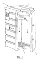
- FIG. 1 shows a view in perspective of a housing 1 according to the invention.
- Housing 1 is constructed from a wall or door 2 for removal, upright side walls 3, a rear wall 6, an upper wall 4 and a lower wall 5. All said walls 2-6 are manufactured in accordance with the sandwich construction described below. In some cases however, only some of the walls are embodied in such manner. It is not necessary in all cases to embody for instance the lower wall or bottom 5 with the reinforced sandwich construction according to the invention, since little temperature influence is exerted on this wall from outside.
- the housing comprises a compartment 7 in which the different control units, for instance a control for the water sampler (not shown), are enclosed.
- a hollow space in which a sampler can be arranged.
- the sampler is herein connected to a passage 8 through wall 3 of the housing, which passage has the function of providing a connection between the sampler inside the housing and the wastewater outside which is to be monitored.
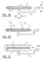
- Figures 2a-2f show the different steps of the manufacturing process of the different walls 2-6 of the housing.
- Set forth in the figures is the manufacture of flat walls. It is however equally well possible to provide the walls with grooves (as shown in figure 1) or to manufacture two or more walls simultaneously. It is even possible to embody a number of the walls (for instance side walls 3, rear wall 6, lower wall 5 and upper wall 4) or the whole housing in a single fabrication process. For the sake of simplicity however, the description is limited to the manufacture of a flat wall.
- FIGS 2a-2f show a rotation moulding process with which the sandwich elements can be manufactured.
- the rotation moulding process shown in the figures has the advantage over many other processing techniques for plastic that the products resulting from the manufacturing process are seamless and practically stress-free.
- the mould of the machine is assembled from an upper mould part 11 and a lower mould part 12.
- Lower mould part 12 is attached fixedly to a rotation shaft 13 mounted rotatably in a support 14.
- Shaft 13 is rotatable using means which are not shown, whereby a rotation in the horizontal plane (arrow P 2 in figure 2b) can be imparted to the mould.
- Support 14 is in turn attached fixedly to a second rotation shaft 16 mounted rotatably in a second support 15.
- the second rotation shaft 16 is rotatable using means which are not shown, whereby a rotation in the vertical plane (arrow P 3 in figure 2b) can be imparted to the mould.
- Mould 11,12 is first of all filled with a measured quantity of a pre-prepared mixture or granulate g of, among other things, plastic powder, preferably polyethylene powder, and optionally a dye to give the mixture a desired colour. Mould parts 11 and 12 are then pressed against each other (arrow P 1 in figure 2a).
- Mould 11,12 can be preheated at determined positions with a gas burner before the mould is placed into an oven (not shown), with the purpose of obtaining a better melt. This is however not always necessary.
- the mould rotates during heating about the two mutually perpendicular shafts 13 and 16 (arrows P 2 and P 3 in figure 2b) so that the force of gravity ensures that every part of the mould wall comes into contact with the plastic.
- the temperature of the oven here depends on the product to be made, but on average it lies between 240 and 300°C.
- the rotation speeds are here kept low to prevent centrifugal effects as much as possible.
- the granulate g thus forms a closed, hollow product against the hot mould wall.
- This is shown in figure 2b, in which it can clearly be seen that, owing to the two rotation movements, granulate g collects against the mould walls, whereby a continuous upper wall 17 and lower wall 18 are formed.
- filler material is injected into the hollow product, i.e. between outer wall 17 and inner wall 18.
- Such double-walled products can generally be provided with foam of polyethylene or polyurethane (PUR foam).
- PUR foam polyurethane
- the polyethylene is generally used to strengthen the product, while the polyurethane is generally used to insulate the products. Both foams have their own processing method.
- PE foam is obtained by introducing between the two walls of the product a special PE powder through which a blowing agent is mixed.
- the product for filling is situated in the mould to prevent the product deforming due to the foam and to "bake" the foam in the oven. Under the influence of the high temperature in the oven the blowing agent mixed through the PE powder transforms from the solid to the gaseous phase and provides the foaming effect.
- the application of PUR foam according to the invention has another processing method however.
- the PUR foam is created by combining two components: an isocyanate and a polyol (as shown in figure 2e). The two components are injected into the double wall of the product during the manufacturing process, as indicated with arrows in figure 2e.
- the product for filling is otherwise situated in the mould in order to prevent the product deforming or bursting apart. Possibly excessive PUR foam and air can escape through venting openings made in the product.
- the mould parts 11 and 12 are therefore released from each other and plastic reinforcing elements v, such as fibres and/or chippings or grains (diameter 2 to 3 mm) are arranged in the still hollow product (figure 2c). While the walls are already formed at this stage of manufacture, they are still in a plastic phase. When the reinforcing elements are added, they have a relatively low temperature, such as close to room temperature. The material of the reinforcing elements is moreover chosen such that the melting temperature of the plastic reinforcing elements s is almost the same as that of the plastic of the wall (preferably PE). The reinforcing elements s hereby retain their form but the outer ends do fuse to the relevant plastic wall.
- plastic reinforcing elements v such as fibres and/or chippings or grains (diameter 2 to 3 mm) are arranged in the still hollow product (figure 2c). While the walls are already formed at this stage of manufacture, they are still in a plastic phase. When the reinforcing elements are added, they have
- Moulds 11 and 12 are then reclosed (figure 2d) and rotated in the above mentioned rotation directions (arrows P 2 and P 3 ). This provides for a uniform distribution of the reinforcing elements over the inner surface of walls 17, 18 of the product.
- Reinforcing elements v have an elongate form in one of the present preferred embodiments, wherein one outer end of a reinforcing element becomes fixedly attached to the wall. The other ends herein become freely suspended in the hollow space (figure 2d).
- the foam creeps between the reinforcing elements so that a reinforcement as it were results which connects the PUR foam practically non-releasably to the plastic wall 17,18.
- a similar process takes place when, in another preferred embodiment, granular reinforcing elements are arranged instead of elongate elements.
- the grains can have a varying size, but preferably have a size of several mm (2-3 mm).
- the moulds After being removed from the oven, the moulds are cooled using large fans and/or water. The moulds still rotate on shafts 13 and 16 during the cooling. As a result of the cooling the product becomes rigid, and can be removed from the mould. A number of products are then further treated with foam and/or provided with hinges and locks.
- the housings in which the fluid samplers characteristically have dimensions of between 0.5 mm and 1.5 mm. Housings can for instance be envisaged with dimensions of 60 x 60 x 110 cm and 90 x 90 x 100 cm.
- the total thickness of the sandwich construction is about 4-8 cm, wherein the walls themselves have a thickness of about 3-4 cm (maximum 6 mm walls).
Landscapes
- Chemical & Material Sciences (AREA)
- Health & Medical Sciences (AREA)
- Life Sciences & Earth Sciences (AREA)
- Clinical Laboratory Science (AREA)
- Chemical Kinetics & Catalysis (AREA)
- Physics & Mathematics (AREA)
- Mechanical Engineering (AREA)
- Hydrology & Water Resources (AREA)
- Engineering & Computer Science (AREA)
- Analytical Chemistry (AREA)
- Biochemistry (AREA)
- General Health & Medical Sciences (AREA)
- General Physics & Mathematics (AREA)
- Immunology (AREA)
- Pathology (AREA)
- Casting Or Compression Moulding Of Plastics Or The Like (AREA)
- Sampling And Sample Adjustment (AREA)
Priority Applications (1)
| Application Number | Priority Date | Filing Date | Title |
|---|---|---|---|
| PL04077311T PL1508437T3 (pl) | 2003-08-14 | 2004-08-13 | Obudowa o strukturze warstwowej i sposób jej wytwarzania |
Applications Claiming Priority (2)
| Application Number | Priority Date | Filing Date | Title |
|---|---|---|---|
| NL1024112 | 2003-08-14 | ||
| NL1024112A NL1024112C2 (nl) | 2003-08-14 | 2003-08-14 | Behuizing met sandwich-constructie en een werkwijze voor het vervaardigen daarvan. |
Publications (3)
| Publication Number | Publication Date |
|---|---|
| EP1508437A2 true EP1508437A2 (de) | 2005-02-23 |
| EP1508437A3 EP1508437A3 (de) | 2006-04-19 |
| EP1508437B1 EP1508437B1 (de) | 2013-10-16 |
Family
ID=34056991
Family Applications (1)
| Application Number | Title | Priority Date | Filing Date |
|---|---|---|---|
| EP04077311.1A Expired - Lifetime EP1508437B1 (de) | 2003-08-14 | 2004-08-13 | Gehäuse mit Sandwichstruktur und Verfahren zur Herstellung |
Country Status (3)
| Country | Link |
|---|---|
| EP (1) | EP1508437B1 (de) |
| NL (1) | NL1024112C2 (de) |
| PL (1) | PL1508437T3 (de) |
Cited By (1)
| Publication number | Priority date | Publication date | Assignee | Title |
|---|---|---|---|---|
| WO2012044878A3 (en) * | 2010-09-30 | 2012-08-23 | Dow Global Technologies Llc | Container modifications to minimize defects during reactive polyurethane flow |
Citations (1)
| Publication number | Priority date | Publication date | Assignee | Title |
|---|---|---|---|---|
| GB2143465A (en) | 1983-07-18 | 1985-02-13 | Bourguignonne Plastique | Composite body moulding process |
Family Cites Families (5)
| Publication number | Priority date | Publication date | Assignee | Title |
|---|---|---|---|---|
| FR2220377A1 (en) * | 1971-05-04 | 1974-10-04 | Brodeau Andre | Anchoring moulding material to metal sheet - using protruding fittings for positive mechanical attachment |
| ZA806596B (en) * | 1980-01-21 | 1981-10-28 | Int Harvester Co | Impact absorbing composite structure |
| US4560607A (en) * | 1984-06-07 | 1985-12-24 | The Duriron Company, Inc. | Method of joining materials by mechanical interlock and article |
| AR011800A1 (es) * | 1997-02-17 | 2000-09-13 | Montell Technology Company Bv | Revestimientos intriores de heladeras mejorados, y heladeras familiares modulares que comprenden dichos revestimientos interiores |
| DE19734803C1 (de) * | 1997-08-12 | 1999-03-25 | Hahlbrock Gmbh | Faserverbundwerkstoff, aus einem Faserverbundwerkstoff hergestelltes Verbindungselement und Verfahren zu seiner Herstellung |
-
2003
- 2003-08-14 NL NL1024112A patent/NL1024112C2/nl not_active IP Right Cessation
-
2004
- 2004-08-13 EP EP04077311.1A patent/EP1508437B1/de not_active Expired - Lifetime
- 2004-08-13 PL PL04077311T patent/PL1508437T3/pl unknown
Patent Citations (1)
| Publication number | Priority date | Publication date | Assignee | Title |
|---|---|---|---|---|
| GB2143465A (en) | 1983-07-18 | 1985-02-13 | Bourguignonne Plastique | Composite body moulding process |
Cited By (2)
| Publication number | Priority date | Publication date | Assignee | Title |
|---|---|---|---|---|
| WO2012044878A3 (en) * | 2010-09-30 | 2012-08-23 | Dow Global Technologies Llc | Container modifications to minimize defects during reactive polyurethane flow |
| US9649794B2 (en) | 2010-09-30 | 2017-05-16 | Dow Global Technologies | Container modifications to minimize defects during reactive polyurethane flow |
Also Published As
| Publication number | Publication date |
|---|---|
| EP1508437A3 (de) | 2006-04-19 |
| EP1508437B1 (de) | 2013-10-16 |
| PL1508437T3 (pl) | 2014-03-31 |
| NL1024112C2 (nl) | 2005-02-15 |
Similar Documents
| Publication | Publication Date | Title |
|---|---|---|
| US6982057B2 (en) | Multi-layer rotational plastic molding | |
| FI95010B (fi) | Menetelmä kuituvahvisteisen kestomuovipolymeeriprofiilin valmistamiseksi sekä menetelmässä käytettävä suulake | |
| CN102209616B (zh) | 模制的模块化建筑物 | |
| CN1938148A (zh) | 由热塑性材料制造成型体的方法 | |
| CN106099382A (zh) | 龙伯透镜天线的制造方法 | |
| WO2020165307A1 (en) | Temperature control system for rotational moulding technology | |
| EP1508437A2 (de) | Gehäuse mit Sandwichstruktur und Verfahren zur Herstellung | |
| KR20060120066A (ko) | 탄성 띠형재와 그 제조 방법 및 장치 | |
| AU627259B2 (en) | Expanded fiber composite structure and process for making said structure | |
| US5453230A (en) | Method for rotationally molding an article with a vulnerable insert | |
| KR101278528B1 (ko) | 점증 압력 수지 이송 성형에 의한 중공 복합재료 구조재 및 그 제조 방법 | |
| US20060057713A1 (en) | Chamber for culturing cells and method for making same | |
| US7273364B2 (en) | Drop box with thermal isolation | |
| CN205439234U (zh) | 方形的吹膜机料斗及吹膜机 | |
| US6630091B2 (en) | Method of manufacturing a screen device | |
| US11958218B2 (en) | Process for moulding polymeric foam core sandwich articles | |
| KR101504658B1 (ko) | 회전방식 금형을 이용한 용기 제조방법 | |
| KR101147823B1 (ko) | 지오그리드와 지오그리드 제조장치 및 제조장치를 이용한 지오그리드 제조방법 | |
| EP1830998B1 (de) | Verfahren zum kombinieren eines ersten materials mit einem verbundmaterial zur herstellung eines hohlkörpers und gemäss diesem verfahren hergestelltes behälterelement | |
| WO1994015780A1 (en) | Vacuum insulating and construction material | |
| RU2389934C2 (ru) | Набор тепло-гидроизолированных труб и способ производства предварительно тепло-гидроизолированной трубы | |
| CN221540643U (zh) | 一种热缩管的扩管装置 | |
| RU2389932C2 (ru) | Набор тепло-гидроизолированных труб и способ производства предварительно тепло-гидроизолированной трубы | |
| CN1249711A (zh) | 适合构造冷冻装置的模塑件及其生产方法 | |
| RU2389933C2 (ru) | Набор тепло-гидроизолированных труб и способ производства предварительно тепло-гидроизолированной трубы |
Legal Events
| Date | Code | Title | Description |
|---|---|---|---|
| PUAI | Public reference made under article 153(3) epc to a published international application that has entered the european phase |
Free format text: ORIGINAL CODE: 0009012 |
|
| AK | Designated contracting states |
Kind code of ref document: A2 Designated state(s): AT BE BG CH CY CZ DE DK EE ES FI FR GB GR HU IE IT LI LU MC NL PL PT RO SE SI SK TR |
|
| AX | Request for extension of the european patent |
Extension state: AL HR LT LV MK |
|
| PUAL | Search report despatched |
Free format text: ORIGINAL CODE: 0009013 |
|
| AK | Designated contracting states |
Kind code of ref document: A3 Designated state(s): AT BE BG CH CY CZ DE DK EE ES FI FR GB GR HU IE IT LI LU MC NL PL PT RO SE SI SK TR |
|
| AX | Request for extension of the european patent |
Extension state: AL HR LT LV MK |
|
| RIC1 | Information provided on ipc code assigned before grant |
Ipc: G01N 1/10 20060101ALI20060227BHEP Ipc: B01L 1/00 20060101ALI20060227BHEP Ipc: B29C 65/56 20060101ALI20060227BHEP Ipc: B29C 37/00 20060101ALI20060227BHEP Ipc: B32B 7/08 20060101AFI20041130BHEP |
|
| 17P | Request for examination filed |
Effective date: 20060825 |
|
| 17Q | First examination report despatched |
Effective date: 20061027 |
|
| AKX | Designation fees paid |
Designated state(s): AT BE BG CH CY CZ DE DK EE ES FI FR GB GR HU IE IT LI LU MC NL PL PT RO SE SI SK TR |
|
| GRAP | Despatch of communication of intention to grant a patent |
Free format text: ORIGINAL CODE: EPIDOSNIGR1 |
|
| INTG | Intention to grant announced |
Effective date: 20130415 |
|
| GRAS | Grant fee paid |
Free format text: ORIGINAL CODE: EPIDOSNIGR3 |
|
| GRAA | (expected) grant |
Free format text: ORIGINAL CODE: 0009210 |
|
| AK | Designated contracting states |
Kind code of ref document: B1 Designated state(s): AT BE BG CH CY CZ DE DK EE ES FI FR GB GR HU IE IT LI LU MC NL PL PT RO SE SI SK TR |
|
| REG | Reference to a national code |
Ref country code: GB Ref legal event code: FG4D |
|
| REG | Reference to a national code |
Ref country code: CH Ref legal event code: EP |
|
| REG | Reference to a national code |
Ref country code: IE Ref legal event code: FG4D |
|
| REG | Reference to a national code |
Ref country code: AT Ref legal event code: REF Ref document number: 636257 Country of ref document: AT Kind code of ref document: T Effective date: 20131115 |
|
| REG | Reference to a national code |
Ref country code: DE Ref legal event code: R096 Ref document number: 602004043572 Country of ref document: DE Effective date: 20131212 |
|
| REG | Reference to a national code |
Ref country code: NL Ref legal event code: T3 |
|
| REG | Reference to a national code |
Ref country code: AT Ref legal event code: MK05 Ref document number: 636257 Country of ref document: AT Kind code of ref document: T Effective date: 20131016 |
|
| PG25 | Lapsed in a contracting state [announced via postgrant information from national office to epo] |
Ref country code: FI Free format text: LAPSE BECAUSE OF FAILURE TO SUBMIT A TRANSLATION OF THE DESCRIPTION OR TO PAY THE FEE WITHIN THE PRESCRIBED TIME-LIMIT Effective date: 20131016 Ref country code: SE Free format text: LAPSE BECAUSE OF FAILURE TO SUBMIT A TRANSLATION OF THE DESCRIPTION OR TO PAY THE FEE WITHIN THE PRESCRIBED TIME-LIMIT Effective date: 20131016 Ref country code: BE Free format text: LAPSE BECAUSE OF FAILURE TO SUBMIT A TRANSLATION OF THE DESCRIPTION OR TO PAY THE FEE WITHIN THE PRESCRIBED TIME-LIMIT Effective date: 20131016 |
|
| PG25 | Lapsed in a contracting state [announced via postgrant information from national office to epo] |
Ref country code: AT Free format text: LAPSE BECAUSE OF FAILURE TO SUBMIT A TRANSLATION OF THE DESCRIPTION OR TO PAY THE FEE WITHIN THE PRESCRIBED TIME-LIMIT Effective date: 20131016 Ref country code: CY Free format text: LAPSE BECAUSE OF FAILURE TO SUBMIT A TRANSLATION OF THE DESCRIPTION OR TO PAY THE FEE WITHIN THE PRESCRIBED TIME-LIMIT Effective date: 20131016 Ref country code: ES Free format text: LAPSE BECAUSE OF FAILURE TO SUBMIT A TRANSLATION OF THE DESCRIPTION OR TO PAY THE FEE WITHIN THE PRESCRIBED TIME-LIMIT Effective date: 20131016 |
|
| PG25 | Lapsed in a contracting state [announced via postgrant information from national office to epo] |
Ref country code: PT Free format text: LAPSE BECAUSE OF FAILURE TO SUBMIT A TRANSLATION OF THE DESCRIPTION OR TO PAY THE FEE WITHIN THE PRESCRIBED TIME-LIMIT Effective date: 20140217 |
|
| REG | Reference to a national code |
Ref country code: DE Ref legal event code: R097 Ref document number: 602004043572 Country of ref document: DE |
|
| PG25 | Lapsed in a contracting state [announced via postgrant information from national office to epo] |
Ref country code: EE Free format text: LAPSE BECAUSE OF FAILURE TO SUBMIT A TRANSLATION OF THE DESCRIPTION OR TO PAY THE FEE WITHIN THE PRESCRIBED TIME-LIMIT Effective date: 20131016 |
|
| PLBE | No opposition filed within time limit |
Free format text: ORIGINAL CODE: 0009261 |
|
| STAA | Information on the status of an ep patent application or granted ep patent |
Free format text: STATUS: NO OPPOSITION FILED WITHIN TIME LIMIT |
|
| PG25 | Lapsed in a contracting state [announced via postgrant information from national office to epo] |
Ref country code: RO Free format text: LAPSE BECAUSE OF FAILURE TO SUBMIT A TRANSLATION OF THE DESCRIPTION OR TO PAY THE FEE WITHIN THE PRESCRIBED TIME-LIMIT Effective date: 20131016 Ref country code: SK Free format text: LAPSE BECAUSE OF FAILURE TO SUBMIT A TRANSLATION OF THE DESCRIPTION OR TO PAY THE FEE WITHIN THE PRESCRIBED TIME-LIMIT Effective date: 20131016 |
|
| 26N | No opposition filed |
Effective date: 20140717 |
|
| PG25 | Lapsed in a contracting state [announced via postgrant information from national office to epo] |
Ref country code: DK Free format text: LAPSE BECAUSE OF FAILURE TO SUBMIT A TRANSLATION OF THE DESCRIPTION OR TO PAY THE FEE WITHIN THE PRESCRIBED TIME-LIMIT Effective date: 20131016 |
|
| REG | Reference to a national code |
Ref country code: DE Ref legal event code: R097 Ref document number: 602004043572 Country of ref document: DE Effective date: 20140717 |
|
| PGFP | Annual fee paid to national office [announced via postgrant information from national office to epo] |
Ref country code: CZ Payment date: 20140807 Year of fee payment: 11 |
|
| PGFP | Annual fee paid to national office [announced via postgrant information from national office to epo] |
Ref country code: PL Payment date: 20140728 Year of fee payment: 11 |
|
| PG25 | Lapsed in a contracting state [announced via postgrant information from national office to epo] |
Ref country code: SI Free format text: LAPSE BECAUSE OF FAILURE TO SUBMIT A TRANSLATION OF THE DESCRIPTION OR TO PAY THE FEE WITHIN THE PRESCRIBED TIME-LIMIT Effective date: 20131016 |
|
| PG25 | Lapsed in a contracting state [announced via postgrant information from national office to epo] |
Ref country code: MC Free format text: LAPSE BECAUSE OF FAILURE TO SUBMIT A TRANSLATION OF THE DESCRIPTION OR TO PAY THE FEE WITHIN THE PRESCRIBED TIME-LIMIT Effective date: 20131016 Ref country code: LU Free format text: LAPSE BECAUSE OF FAILURE TO SUBMIT A TRANSLATION OF THE DESCRIPTION OR TO PAY THE FEE WITHIN THE PRESCRIBED TIME-LIMIT Effective date: 20140813 |
|
| REG | Reference to a national code |
Ref country code: CH Ref legal event code: PL |
|
| PG25 | Lapsed in a contracting state [announced via postgrant information from national office to epo] |
Ref country code: LI Free format text: LAPSE BECAUSE OF NON-PAYMENT OF DUE FEES Effective date: 20140831 Ref country code: CH Free format text: LAPSE BECAUSE OF NON-PAYMENT OF DUE FEES Effective date: 20140831 |
|
| REG | Reference to a national code |
Ref country code: IE Ref legal event code: MM4A |
|
| PG25 | Lapsed in a contracting state [announced via postgrant information from national office to epo] |
Ref country code: IE Free format text: LAPSE BECAUSE OF NON-PAYMENT OF DUE FEES Effective date: 20140813 |
|
| PG25 | Lapsed in a contracting state [announced via postgrant information from national office to epo] |
Ref country code: CZ Free format text: LAPSE BECAUSE OF NON-PAYMENT OF DUE FEES Effective date: 20150813 |
|
| PG25 | Lapsed in a contracting state [announced via postgrant information from national office to epo] |
Ref country code: BG Free format text: LAPSE BECAUSE OF FAILURE TO SUBMIT A TRANSLATION OF THE DESCRIPTION OR TO PAY THE FEE WITHIN THE PRESCRIBED TIME-LIMIT Effective date: 20131016 |
|
| PG25 | Lapsed in a contracting state [announced via postgrant information from national office to epo] |
Ref country code: GR Free format text: LAPSE BECAUSE OF FAILURE TO SUBMIT A TRANSLATION OF THE DESCRIPTION OR TO PAY THE FEE WITHIN THE PRESCRIBED TIME-LIMIT Effective date: 20140117 |
|
| PG25 | Lapsed in a contracting state [announced via postgrant information from national office to epo] |
Ref country code: HU Free format text: LAPSE BECAUSE OF FAILURE TO SUBMIT A TRANSLATION OF THE DESCRIPTION OR TO PAY THE FEE WITHIN THE PRESCRIBED TIME-LIMIT; INVALID AB INITIO Effective date: 20040813 Ref country code: TR Free format text: LAPSE BECAUSE OF FAILURE TO SUBMIT A TRANSLATION OF THE DESCRIPTION OR TO PAY THE FEE WITHIN THE PRESCRIBED TIME-LIMIT Effective date: 20131016 |
|
| REG | Reference to a national code |
Ref country code: FR Ref legal event code: PLFP Year of fee payment: 13 |
|
| PG25 | Lapsed in a contracting state [announced via postgrant information from national office to epo] |
Ref country code: PL Free format text: LAPSE BECAUSE OF NON-PAYMENT OF DUE FEES Effective date: 20150813 |
|
| REG | Reference to a national code |
Ref country code: FR Ref legal event code: PLFP Year of fee payment: 14 |
|
| REG | Reference to a national code |
Ref country code: FR Ref legal event code: PLFP Year of fee payment: 15 |
|
| REG | Reference to a national code |
Ref country code: NL Ref legal event code: PD Owner name: EFCON WATER B.V.; NL Free format text: DETAILS ASSIGNMENT: CHANGE OF OWNER(S), ASSIGNMENT; FORMER OWNER NAME: VERKROOST, PAULUS ARTHUR UBALD LUCAS Effective date: 20220902 |
|
| REG | Reference to a national code |
Ref country code: DE Ref legal event code: R081 Ref document number: 602004043572 Country of ref document: DE Owner name: EFCON WATER B.V., NL Free format text: FORMER OWNER: VERKROOST, PAULUS ARTHUR UBALD LUCAS, VIANEN, NL |
|
| REG | Reference to a national code |
Ref country code: GB Ref legal event code: 732E Free format text: REGISTERED BETWEEN 20220825 AND 20220831 |
|
| PGFP | Annual fee paid to national office [announced via postgrant information from national office to epo] |
Ref country code: NL Payment date: 20230826 Year of fee payment: 20 |
|
| PGFP | Annual fee paid to national office [announced via postgrant information from national office to epo] |
Ref country code: IT Payment date: 20230822 Year of fee payment: 20 Ref country code: GB Payment date: 20230828 Year of fee payment: 20 |
|
| PGFP | Annual fee paid to national office [announced via postgrant information from national office to epo] |
Ref country code: FR Payment date: 20230825 Year of fee payment: 20 Ref country code: DE Payment date: 20230829 Year of fee payment: 20 |
|
| REG | Reference to a national code |
Ref country code: DE Ref legal event code: R071 Ref document number: 602004043572 Country of ref document: DE |
|
| REG | Reference to a national code |
Ref country code: NL Ref legal event code: MK Effective date: 20240812 |
|
| REG | Reference to a national code |
Ref country code: GB Ref legal event code: PE20 Expiry date: 20240812 |
|
| PG25 | Lapsed in a contracting state [announced via postgrant information from national office to epo] |
Ref country code: GB Free format text: LAPSE BECAUSE OF EXPIRATION OF PROTECTION Effective date: 20240812 |
|
| PG25 | Lapsed in a contracting state [announced via postgrant information from national office to epo] |
Ref country code: GB Free format text: LAPSE BECAUSE OF EXPIRATION OF PROTECTION Effective date: 20240812 |