EP1508460A1 - Suspension hydrpneumatique - Google Patents
Suspension hydrpneumatique Download PDFInfo
- Publication number
- EP1508460A1 EP1508460A1 EP04103583A EP04103583A EP1508460A1 EP 1508460 A1 EP1508460 A1 EP 1508460A1 EP 04103583 A EP04103583 A EP 04103583A EP 04103583 A EP04103583 A EP 04103583A EP 1508460 A1 EP1508460 A1 EP 1508460A1
- Authority
- EP
- European Patent Office
- Prior art keywords
- valve
- pressure
- solenoid valve
- suspension device
- annular space
- Prior art date
- Legal status (The legal status is an assumption and is not a legal conclusion. Google has not performed a legal analysis and makes no representation as to the accuracy of the status listed.)
- Granted
Links
- 239000000725 suspension Substances 0.000 title claims description 53
- 239000007788 liquid Substances 0.000 claims description 21
- 239000012530 fluid Substances 0.000 claims description 3
- 230000000712 assembly Effects 0.000 abstract 1
- 238000000429 assembly Methods 0.000 abstract 1
- 230000006870 function Effects 0.000 description 7
- 230000008901 benefit Effects 0.000 description 4
- 238000011161 development Methods 0.000 description 4
- 230000018109 developmental process Effects 0.000 description 4
- 230000009467 reduction Effects 0.000 description 4
- 230000009286 beneficial effect Effects 0.000 description 2
- 230000000694 effects Effects 0.000 description 2
- 230000036316 preload Effects 0.000 description 2
- 230000001105 regulatory effect Effects 0.000 description 2
- 241000243251 Hydra Species 0.000 description 1
- 230000006978 adaptation Effects 0.000 description 1
- 230000008859 change Effects 0.000 description 1
- 230000007423 decrease Effects 0.000 description 1
- 230000001419 dependent effect Effects 0.000 description 1
- 238000010586 diagram Methods 0.000 description 1
- 230000005281 excited state Effects 0.000 description 1
- 239000000446 fuel Substances 0.000 description 1
- QRXWMOHMRWLFEY-UHFFFAOYSA-N isoniazide Chemical compound NNC(=O)C1=CC=NC=C1 QRXWMOHMRWLFEY-UHFFFAOYSA-N 0.000 description 1
- 238000000034 method Methods 0.000 description 1
- 238000012986 modification Methods 0.000 description 1
- 230000004048 modification Effects 0.000 description 1
- 238000010992 reflux Methods 0.000 description 1
- 230000004044 response Effects 0.000 description 1
- 230000035939 shock Effects 0.000 description 1
Images
Classifications
-
- B—PERFORMING OPERATIONS; TRANSPORTING
- B60—VEHICLES IN GENERAL
- B60G—VEHICLE SUSPENSION ARRANGEMENTS
- B60G17/00—Resilient suspensions having means for adjusting the spring or vibration-damper characteristics, for regulating the distance between a supporting surface and a sprung part of vehicle or for locking suspension during use to meet varying vehicular or surface conditions, e.g. due to speed or load
- B60G17/02—Spring characteristics, e.g. mechanical springs and mechanical adjusting means
- B60G17/04—Spring characteristics, e.g. mechanical springs and mechanical adjusting means fluid spring characteristics
- B60G17/056—Regulating distributors or valves for hydropneumatic systems
-
- B—PERFORMING OPERATIONS; TRANSPORTING
- B60—VEHICLES IN GENERAL
- B60G—VEHICLE SUSPENSION ARRANGEMENTS
- B60G17/00—Resilient suspensions having means for adjusting the spring or vibration-damper characteristics, for regulating the distance between a supporting surface and a sprung part of vehicle or for locking suspension during use to meet varying vehicular or surface conditions, e.g. due to speed or load
- B60G17/015—Resilient suspensions having means for adjusting the spring or vibration-damper characteristics, for regulating the distance between a supporting surface and a sprung part of vehicle or for locking suspension during use to meet varying vehicular or surface conditions, e.g. due to speed or load the regulating means comprising electric or electronic elements
- B60G17/0152—Resilient suspensions having means for adjusting the spring or vibration-damper characteristics, for regulating the distance between a supporting surface and a sprung part of vehicle or for locking suspension during use to meet varying vehicular or surface conditions, e.g. due to speed or load the regulating means comprising electric or electronic elements characterised by the action on a particular type of suspension unit
-
- B—PERFORMING OPERATIONS; TRANSPORTING
- B60—VEHICLES IN GENERAL
- B60G—VEHICLE SUSPENSION ARRANGEMENTS
- B60G21/00—Interconnection systems for two or more resiliently-suspended wheels, e.g. for stabilising a vehicle body with respect to acceleration, deceleration or centrifugal forces
- B60G21/02—Interconnection systems for two or more resiliently-suspended wheels, e.g. for stabilising a vehicle body with respect to acceleration, deceleration or centrifugal forces permanently interconnected
- B60G21/06—Interconnection systems for two or more resiliently-suspended wheels, e.g. for stabilising a vehicle body with respect to acceleration, deceleration or centrifugal forces permanently interconnected fluid
- B60G21/073—Interconnection systems for two or more resiliently-suspended wheels, e.g. for stabilising a vehicle body with respect to acceleration, deceleration or centrifugal forces permanently interconnected fluid between wheels on the same axle but on different sides of the vehicle, i.e. the left and right wheel suspensions being interconnected
-
- B—PERFORMING OPERATIONS; TRANSPORTING
- B60—VEHICLES IN GENERAL
- B60G—VEHICLE SUSPENSION ARRANGEMENTS
- B60G2202/00—Indexing codes relating to the type of spring, damper or actuator
- B60G2202/40—Type of actuator
- B60G2202/41—Fluid actuator
- B60G2202/413—Hydraulic actuator
-
- B—PERFORMING OPERATIONS; TRANSPORTING
- B60—VEHICLES IN GENERAL
- B60G—VEHICLE SUSPENSION ARRANGEMENTS
- B60G2202/00—Indexing codes relating to the type of spring, damper or actuator
- B60G2202/40—Type of actuator
- B60G2202/41—Fluid actuator
- B60G2202/414—Fluid actuator using electrohydraulic valves
-
- B—PERFORMING OPERATIONS; TRANSPORTING
- B60—VEHICLES IN GENERAL
- B60G—VEHICLE SUSPENSION ARRANGEMENTS
- B60G2500/00—Indexing codes relating to the regulated action or device
- B60G2500/02—Supply or exhaust flow rates; Pump operation
Definitions
- the invention relates to a hydropneumatic Suspension device with at least one hydraulic Suspension cylinder, the cylinder space and annulus each with at least one pressure accumulator in connection and means Valve arrangements optionally with a pressure source and a Tank are connectable.
- the suspension device should preferably be sprung Wheel suspensions of vehicles, in particular of agricultural or industrial vehicles, applied become.
- the suspension can be a Independent suspension or the sprung suspension of a Act vehicle axle.
- the at least one suspension cylinder is between vehicle body and wheel or vehicle axle arranged.
- the design of a hydropneumatic suspension is especially in agricultural or industrial Working machines, such as tractors, a special one Challenge because extreme axle load variations are possible here are.
- the axle load bandwidth usually exceeds that at Diaphragm storage possible pressure ratio.
- To the Work area of the pressure accumulator is to be able to therefore biased the system. This bias acts like a additional axle load, reducing the ratio of minimum to maximum axle load can be reduced.
- the bias of the system is rarely over one mechanical preload, which is also an easy acting cylinder can be used.
- a double-acting hydraulic cylinder is used in the the annulus side via a pressure accumulator with a is biased to certain pressure.
- the set on the annulus side pressure can either the maximum system pressure correspond (DE-A-43 08 460) or Pressure is regulated by a pressure regulator preselected value (DE-C-42 42 448).
- Both Methods like any hydropneumatic system, are inherent, that the spring rate according to a given function in Essentially square depends on the axle load. For one constant build-up natural frequency, however, would be a linear one Dependence ideal.
- DE-A-41 20 758 is a hydropneumatic vehicle suspension of the type mentioned above, in the adaptation to large Achslastsp Dahl in the supply line to the annulus hydraulically operated control valve is arranged, the on the one hand the pressure in the annulus and on the other hand the pressure the cylinder space is exposed, so that the pressure in Annular space regulated as a function of the pressure in the cylinder space becomes. This is to a higher spring stiffness in the area be reached smaller axle loads.
- a certain axle load can be different Ballast istszuident be generated on the vehicle.
- the weight of a heavy plow balance and provide sufficient load on the front axle bring ballast weights at the front of the tractor assemble.
- this ballast can be the same Axle load at the front axle results like a tractor, the equipped with neither a plow nor with front weights.
- the spring stiffness can not be different Ballast conditions and working or driving conditions of Vehicle react, d. H. the spring stiffness is independent from these states and depends only on each one prevailing axle load. This can be done, for example cause a heavily ballasted tractor with respect to the Nickeigenfrequenz is softly sprung during the Unballasted tractor is too hard.
- a hydropneumatic suspension device of the beginning specify the type mentioned by which the aforementioned Problems are overcome.
- a given unchanging quadratic dependence of the spring rate of the axle load to be countered and the spring rate should Ballast conditions and working or driving conditions of Vehicle adaptable and not just from the current Suspend axle load.
- the hydropneumatic suspension device contains at least one hydraulic suspension cylinder, in particular a double-acting hydraulic cylinder whose Cylinder space and annulus each with at least one Pressure accumulator in connection.
- the suspension cylinder can for example, between the chassis of a vehicle and its Wheel or axle be arranged.
- valve arrangements let the cylinder space and the annulus be independent from each other to a pressure source and to a tank.
- This suspension device is characterized in that the annular space associated valve assembly at least a first having electrically controllable solenoid valve, which the Annulus connects to the pressure source, and a second one having electrically controllable solenoid valve, which the Annulus connects to the tank. Furthermore, at least a pressure sensor is provided whose signals for driving the first and second solenoid valve are used.
- the pressure sensor is preferably a Annulus pressure sensor. Alternatively or in addition to this can also the cylinder chamber pressure measured and used for control become. For this purpose, z. B. a separate Cylinder chamber pressure sensor may be provided. It is, however possible to provide a switching valve, which optionally the Annulus or the cylinder chamber connects to the pressure sensor.
- the setting of the annulus pressure is done via the two Solenoid valves, which by generated by a control unit Control currents can be controlled.
- the annulus pressure sensor reports the annulus pressure as a signal to the control unit. These compares the annulus pressure with predefinable pressure setpoints and generates corresponding control signals for the solenoid valves. Is the pressure in the annulus smaller than a predefinable Target pressure, so the first solenoid valve is opened, so that Liquid from the pressure source to the annulus and to the associated annulus memory can flow and the annulus pressure increases. Is the pressure in the annulus greater than a predeterminable Target pressure, so the second solenoid valve is opened, so that Liquid from the annulus and from the associated Annular reservoir can drain to the tank and the annulus pressure decreases.
- this suspension device can the annular space side Change the preload of the axle suspension within wide limits.
- the annulus pressure and thus the Suspension characteristic within given physical Set limits arbitrarily, so that on the one hand a fixed quadratic dependence of the spring rate on the axle load be met and z. B. a more linear Spring characteristic can be adjusted.
- the suspension device according to the invention by suitable electrical control of the solenoid valves to different Ballast conditions, speeds and Operating conditions of the vehicle respond.
- the Suspension characteristics can thus be automatically and on optimal way individually to different driving and Adjust work assignments.
- the suspension device has moreover the particular advantage that the pressure in the annulus Within preset limits in steps or continuously to set any value. This will affect Disturbances due to pressure fluctuations both on the Supply side (changed pump pressure by additional Consumer) and on the annulus side (by Federierien) only very limited, since no pressures to direct control of the solenoid valves are used.
- At least one of the two solenoid valves is on simple seat-tight solenoid valve. It may be, for example to an electromagnetically actuated on-off valve (Switching valve) act when creating a suitable electrical signal opens and otherwise closes.
- Switching valve electromagnetically actuated on-off valve
- first solenoid valve in its closed (disconnected, de-energized) position a non-return function, the one Liquid inflow from the pressure source to the annulus prevented.
- This seat-tight check valve provides in particularly effective way that when switched off first solenoid valve leakage from the pressure source to Annulus side of the hydraulic cylinder is omitted.
- the second Solenoid valve in its closed (disconnected, de-energized) position contains a kickback function, the one Liquid leakage from the annulus to the tank prevented.
- This seat-tight check valve provides in particularly effective Way that when switched off the second solenoid valve a Leakage from the annulus side of the hydraulic cylinder to the tank omitted.
- the first solenoid valve when the first solenoid valve is open Liquid reflux from the annulus of the hydraulic cylinder to To prevent pressure source, it is appropriate to a to provide appropriate check valve, in series with the first solenoid valve is arranged.
- the check valve For example, between the annulus of Hydraulic cylinder and the first solenoid valve may be arranged.
- the first and / or the second Solenoid valve is an on-off valve (such as poppet valve), such as for example as model SV08-20 by the company HydraForce, Lincolnshire, IL, USA
- an on-off valve such as poppet valve
- An expedient development of the invention sees To this end, the use of an aperture in front, in series is arranged with the respective solenoid valve.
- a first aperture and / or between the annulus and the second Solenoid valve be provided a second aperture.
- the aperture can be integrated into the associated valve.
- the usage of apertures allows a controlled adjustment of the Annulus pressure and may also be related to a load-sensing control be beneficial.
- a flow resistance is considered below which can be designed in different ways, For example, as a local constriction (aperture) or as extending over a longer flow path constriction (Throttle).
- a proportionally effective, seat-tight valve used, as for example as Model SP08-20 by Hydra Force, Lincolnshire, IL, USA is offered.
- proportional valves instead of ON-OFF valves can basically to a the Flow limiting aperture are dispensed with. Indeed can be a shutter associated with a load-sensing control still be useful.
- the first solenoid valve is an electrical controllable directional control valve, in particular a 3/2-way valve, which in its currentless position its annular space side Connection with its tank-side connection connects (Fuel station) and in the excited state its Pressure source side connection with the annular space side Connection connects (pressure source position).
- the directional valve It can be both a switching valve and a act proportionally controllable valve.
- a Proportional valve is a flow restrictor not mandatory.
- first and / or second solenoid valve Proportional pressure control valve or on Proportional pressure relief valve may be advantageous as you for example, as model TS98-31 or TS08-27 by the company. HydraForce, Lincolnshire, IL, USA.
- first solenoid valve Proportional pressure control valve for controlled pressure relief (according to a predetermined time characteristic) on the discharge side to Tank as a second solenoid valve Proportional pressure relief valve and on the load side from the pressure source as the first solenoid valve Proportional pressure control valve can be used.
- the pressure source is expediently a hydraulic pump. It For example, it may be a hydraulic pump that already for other hydraulic consumers of the vehicle Available. To use the hydraulic pump economically To be able to, is often a pump with a load-sensing function used, in which the required system pressure for Control of the pump is used.
- the hydraulic pump promotes hydraulic fluid only when required and leaves otherwise in a low-power stand-by mode over.
- the Control connection of the load-sensing pump via a control line with the annular space side connection of the first solenoid valve to connect. If the pressure prevailing at this port exceeds a shutter or a proportional solenoid valve is reduced to the tank down (not energized position of Solenoid valve), there is no pressure medium requirement and the load-sensing pump goes into its stand-by mode.
- One Pressure reduction from the annulus of the hydraulic cylinder is here prevented by a check valve.
- the first solenoid valve opens the connection to the pump, so rises the annular space-side pressure on. This pressure increase is from the Load-sensing pump perceived which swings out and theirs Output pressure is adjusted so that it always by 30, for example bar is above the pressure on the annular space side.
- the first solenoid valve is not connected to the tank it is for proper load-sensing operation required that the pressure of the pressure source not constantly corresponds to the annular space-side pressure, but the Required according degraded.
- the control line via a third orifice or throttle to connect to the tank.
- valves of the suspension device according to the invention summarized in a common control block.
- this control block can also be a valve assembly for Level control, which the liquid inflow and outflow on the Cylinder room side controls, be integrated.
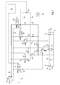
- the vehicle suspension system shown in Fig. 1 is for Suspension of a steerable, pendulum-suspended, not closer Tractor front axle shown determined. It contains two Cylinder 10, 12.
- the two cylinder chambers 14, 16 of the Hydraulic cylinder 10, 12 and the two annular spaces 18, 20 of the two hydraulic cylinders 10, 12 are each about Hydraulic lines 22, 24 with each other and with an associated Hydraulic accumulator 26, 28 connected.
- the cylinder space side hydraulic line 22 (cylinder chamber side the spring circuit) is via a first aperture 30 and a first seat-tight switching valve 32 with a liquid container or Tank 34 connected.
- the first switching valve 32 can be through electrical signals between a flow position and a Lock position, which ensures that no liquid inadvertently from the cylinder room side of the Federnikes to tank 34 can escape, switch.
- the cylinder space-side hydraulic line 22 is further over a check valve 36, a second orifice 38 and a second one seat-tight switching valve 40 with a pressure source in which it is a controllable load-sensing pump 42, connected.
- the second switching valve 40 can be through electrical signals between a flow position and a Lock position, which ensures that no liquid inadvertently from the hydraulic pump 42 in the Spring circuit arrives, switch over.
- the check valve 36 locks the liquid flow in the opposite way as the second Switching valve 40 to prevent leakage when the pressure in the cylinder chamber side of the spring circuit is greater than the Pressure of the supply line 44.
- This valve arrangement serves the level control.
- the first switching valve 32 energized
- its slide switches to the "open" position and Hydraulic fluid flows out of the cylinder chamber side Hydraulic line 22 controlled via the first panel 30 to Tank 34.
- the second Switching valve 40 is opened, the liquid flows from first the supply line 44 via the second aperture 38 in a Load-sensing line 46 and reports via a shuttle valve 48th the pressure medium requirement to the control terminal 43 of the Hydraulic pump 42. This regulates the pressure until, until the check valve 36 opens and liquid in the Cylinder-space-side hydraulic line 22 flows.
- the volume flow is limited, on the other hand also produces a pressure drop, so that the Load-sensing system always on the cylinder room side prevailing pressure is reported.
- the pump 42 pivots not full, but always provides a pressure that z. B. 30 bar above the cylinder space pressure.
- the second switching valve 40 is open Volume flow through a third aperture 50 back to the tank 34th This additional, provided by the third panel 50 Cross-section is needed to close the second one Switching valve 40 the load-sensing pressure to the tank 34 toward relieve.
- first switching valve 32 and the first orifice 30 and the second switching valve 40 and the second aperture 38 also each a proportionally controlled, seat-tight 2/2-way valve can be used, which can be opened by a targeted measure current controlled.
- the cylinder chamber side of the spring circuit namely the Hydraulic line 22 is connected via a pressure limiting valve 52 a certain maximum pressure, usually from the Save is determined, secured.
- a drain valve 54 is used in service case, the cylinder chamber side of the pressure to relieve.
- a Inventive suspension device This consists according to Fig. 1 essentially of an electrically adjustable seated first solenoid valve 60, one electrically adjustable seat-tight second solenoid valve 62, one Check valve 64 and a pressure relief valve 66th
- the first solenoid valve 60 and the check valve 64 are in a first branch 68 arranged in series and connect the to the pump 42 leading supply line 44 with the The annular space-side hydraulic line 24. This prevents the Check valve 64 is a liquid return flow from the annulus to the pump 42.
- the second solenoid valve 62 is in a second Branch 70 is arranged and connects the annular space side Hydraulic line 24 with a leading to the tank 34 Tank line 71.
- Parallel to the second branch 70 is the Pressure relief valve 66 disposed in a third branch 72 and also connects the annular space side hydraulic line 24 with the tank 34.
- the pressure relief valve 66 prevents that the pressure in the annular spaces 18, 20 and in the Annulus pressure accumulator 28 via a predetermined pressure increases.
- the two solenoid valves 60, 62 are between a closed and an open position switchable.
- a kickback function the closed valve position, a liquid flow from the pump 42 to the annular space side hydraulic line 22nd prevented, leaving no or only a negligible low leakage from the pressure source to the annulus side given is.
- the second solenoid valve 62 is also a Non-return function integrated, when closed Valve position a liquid drain from the Prevents annular space-side hydraulic line 22 to the tank 34, so that no or only negligible leakage is given from the annulus side to the tank.
- the Limiting liquid flow is in the first branch 68 a first aperture 74 and in the second branch 70 a second aperture 75th arranged.
- the pressure in the load-sensing line 76 are reduced to the tank 34 out without Liquid from the annular space side hydraulic line 24th flows.
- the tank pressure is connected to the load-sensing line.
- the pressure in the increases Load-sensing line 76 on. This pressure increase is from the Load-sensing pump perceived which swings out and theirs Output pressure is adjusted so that it always by 30, for example bar is above the pressure on the annular space side.
- a drain valve 80 is in case of service used to relieve pressure on the annulus side.
- the two switching valve 32, 40 and the two solenoid valves 60, 62 are driven by an electrical control unit 82.
- the control unit 82 receives signals from a not shown Position transmitter, which is used for the level control by means of Switching valves 32, 40 are used.
- the control unit 82 controls the two solenoid valves 60, 62 on.
- the solenoid valves 60, 62 are closed in de-energized position and energized position open.
- the control unit 82 contains signals from a pressure sensor 84, the connected to the annular space side hydraulic line 24 is and the annulus pressure recorded. Sinks the measured Annulus pressure below a predetermined value, it will first solenoid valve 60 is opened, so that a pressure increase in Annulus takes place. Is the annulus pressure above the specifiable Value, the second solenoid valve 62 is opened and the Annular space pressure can degrade to the tank 34.
- the predefinable value for the annulus pressure can by a Operator according to the present ballast of the vehicle can be specified. This value is preferred modified by parameters. For this purpose evaluates the Control unit 82 also measured values of a not shown Vehicle speed sensor and a tensile force sensor. The spring stiffness can thus be automatically in Dependence of the vehicle speed and / or thereof adjust whether a device is attached to the vehicle or is mounted, which is closed from the tension sensor signal can be.
- the control unit 82 may, if appropriate is also signals of a rear and / or front PTO or receive and evaluate other vehicle aggregates.
- the Ballasting of the vehicle can be, for example, by the Set the operator by means of a switch. she will also detected by the control unit and for adjustment the two solenoid valves 60, 62 evaluated.
- the mentioned and Further signals can the control unit 82, for example via a CAN-BUS be made available.
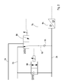
- FIG. 2 shows an alternative with respect to FIG. 1 Variant of one of the setting of the annulus pressure serving suspension device according to the invention. Instead of shown in Fig. 1 switching valves 60, and 62 are shown in FIG. 2 electrically switchable proportional valves 86, 88 used.
- the first proportional valve 86 is a 3/2-way valve and allows an optional connection of the annular space side Hydraulic line 24 to the tank (via the tank line 71) or with the pump 42 (via the supply line 44).
- the first Proportional valve 86 is similar to FIG. 1 by a in Fig. 2 control unit, not shown driven.
- a check valve 64 In the The annular space-side supply line 90 of the first proportional valve 86th there is a check valve 64, which is a Liquid drainage from the annulus side prevented. A Aperture is not required in this branch 90, since the Liquid flow through the first proportional valve 86 infinitely adjustable.
- the second proportional valve 88 serves, if necessary, the Pressure reduction in the annular space-side hydraulic line 24, such as this has already been explained with reference to FIG. 1.
- a proportional valve may be in the execution 2, a diaphragm, as shown in Fig. 1, omitted.
Landscapes
- Engineering & Computer Science (AREA)
- Mechanical Engineering (AREA)
- Vehicle Body Suspensions (AREA)
Applications Claiming Priority (2)
| Application Number | Priority Date | Filing Date | Title |
|---|---|---|---|
| DE10337600 | 2003-08-16 | ||
| DE10337600A DE10337600A1 (de) | 2003-08-16 | 2003-08-16 | Hydropneumatische Federungseinrichtung |
Publications (2)
| Publication Number | Publication Date |
|---|---|
| EP1508460A1 true EP1508460A1 (fr) | 2005-02-23 |
| EP1508460B1 EP1508460B1 (fr) | 2008-01-16 |
Family
ID=34042167
Family Applications (1)
| Application Number | Title | Priority Date | Filing Date |
|---|---|---|---|
| EP04103583A Expired - Lifetime EP1508460B1 (fr) | 2003-08-16 | 2004-07-27 | Suspension hydrpneumatique |
Country Status (5)
| Country | Link |
|---|---|
| US (1) | US7059127B2 (fr) |
| EP (1) | EP1508460B1 (fr) |
| AT (1) | ATE383962T1 (fr) |
| AU (1) | AU2004203877B2 (fr) |
| DE (2) | DE10337600A1 (fr) |
Cited By (2)
| Publication number | Priority date | Publication date | Assignee | Title |
|---|---|---|---|---|
| WO2018153677A1 (fr) * | 2017-02-21 | 2018-08-30 | Hydac Systems & Services Gmbh | Dispositif de suspension |
| US12365209B2 (en) * | 2023-10-25 | 2025-07-22 | Hl Mando Corporation | Vehicle suspension system for vehicle height adjustment and control method therefor |
Families Citing this family (19)
| Publication number | Priority date | Publication date | Assignee | Title |
|---|---|---|---|---|
| DE102006051894A1 (de) * | 2006-10-31 | 2008-05-08 | Deere & Company, Moline | Federungssystem |
| CA2688291C (fr) * | 2007-06-18 | 2015-02-17 | Deere & Company | Commande de pression differentielle |
| DE102007038933A1 (de) * | 2007-08-17 | 2009-02-19 | Hydac System Gmbh | Dämpfungssystem |
| DE102008048460B4 (de) | 2008-09-23 | 2022-04-21 | Franz Xaver Meiller Fahrzeug- Und Maschinenfabrik - Gmbh & Co Kg | Ersatzradaufnahmeeinrichtung und damit ausgerüsteter Lastkraftwagen |
| US8876452B2 (en) * | 2009-04-03 | 2014-11-04 | T&T Engineering Services, Inc. | Raise-assist and smart energy system for a pipe handling apparatus |
| US8291925B2 (en) * | 2009-10-13 | 2012-10-23 | Eaton Corporation | Method for operating a hydraulic actuation power system experiencing pressure sensor faults |
| EP2361800B1 (fr) * | 2010-02-17 | 2013-04-24 | L & P Swiss Holding AG | Dispositif d'ajustement pour siège et procédé de fonctionnement d'un dispositif d'ajustement |
| US8915073B1 (en) * | 2010-09-13 | 2014-12-23 | Daniel Theobald | Fluid power device, method and system |
| DE102012210899A1 (de) * | 2012-06-26 | 2014-01-02 | Mahle International Gmbh | Hydraulikfördereinrichtung und Hydrauliksystem |
| DE102012106185B3 (de) | 2012-07-10 | 2013-11-21 | Fsp Fluid Systems Partners Holding Ag | Steueranordnung für ein hydropneumatisches Federungssystem sowie hydropneumatisches Federungssystem mit einer solchen Steueranordnung |
| DE102012022030A1 (de) | 2012-11-12 | 2014-05-15 | Deere & Company | Federungseinrichtung für eine beweglich gelagerte Fahrzeugachse |
| DE102013102069A1 (de) | 2013-03-01 | 2014-09-04 | Fsp Fluid Systems Partners Holding Ag | Proportional-Wegeventil sowie hydraulische Schaltung und hydropneumatisches Federungssystem mit einem derartigen Ventil |
| US9322416B2 (en) | 2013-03-11 | 2016-04-26 | Hydraforce, Inc. | Multi-functional proportional control valve for hydraulic suspension system for vehicle |
| DE102013010298A1 (de) | 2013-06-19 | 2014-12-24 | Bomag Gmbh | Baumaschine, insbesondere Straßenfräse, und Verfahren zum Ausgleichen von Bodenunebenheiten für eine solche Baumaschine |
| DE102014019168A1 (de) | 2014-12-19 | 2016-06-23 | Bomag Gmbh | BAUMASCHINE, INSBESONDERE STRAßENFRÄSE, UND VERFAHREN ZUM AUSGLEICHEN VON BODENUNEBENHEITEN FÜR EINE SOLCHE BAUMASCHINE |
| CN104691270B (zh) * | 2015-01-20 | 2017-12-29 | 徐工消防安全装备有限公司 | 自行走式高空作业车车桥平衡控制系统 |
| DE102018010153B4 (de) | 2018-12-28 | 2021-10-28 | Bomag Gmbh | Baumaschine, insbesondere Straßenfräse, sowie Verfahren zur Steuerung der Hubposition einer Kolben-Zylinder-Einheit einer Hubsäule einer Baumaschine |
| US11667172B2 (en) | 2020-07-30 | 2023-06-06 | Dana Motion Systems Italia S.R.L. | Suspension system and method for operation of said system |
| US11685218B2 (en) | 2020-07-30 | 2023-06-27 | Dana Motion Systems Italia S.R.L. | Hydraulic suspension system and method for operation of said system |
Citations (4)
| Publication number | Priority date | Publication date | Assignee | Title |
|---|---|---|---|---|
| DE4120758A1 (de) * | 1990-06-28 | 1992-01-02 | Zahnradfabrik Friedrichshafen | Hydropneumatische federung fuer fahrzeuge |
| DE4118822A1 (de) * | 1991-06-07 | 1992-12-10 | Rexroth Mannesmann Gmbh | Steuereinrichtung zur zu- und abfuehrung von arbeitsfluessigkeit bei einem hydraulischen arbeitsraum |
| DE19748224A1 (de) * | 1997-10-31 | 1999-05-12 | Deere & Co | Hydropneumatische Achsfederung für angetriebene Fahrzeugachsen |
| EP1188587A2 (fr) * | 2000-05-25 | 2002-03-20 | Husco International, Inc. | Suspension régénératrice pour un véhicule tout-terrain |
Family Cites Families (6)
| Publication number | Priority date | Publication date | Assignee | Title |
|---|---|---|---|---|
| DE4221126C2 (de) * | 1992-06-26 | 1994-08-11 | Hemscheidt Maschf Hermann | Hydropneumatisches Federungssystem |
| DE4242448C1 (de) | 1992-12-16 | 1994-03-31 | Integral Hydraulik Co | Hydro-pneumatische Federungseinrichtung |
| DE4308460A1 (de) | 1993-03-17 | 1994-09-22 | Fendt Xaver Gmbh & Co | Arbeitsfahrzeug mit einer hydropneumatischen, niveaugeregelten Achsfederung |
| KR100286517B1 (ko) * | 1996-12-03 | 2001-04-16 | 사쿠마 하지메 | 건설 기계용 제어 장치 |
| DE19719076C2 (de) | 1997-05-06 | 2000-05-04 | Integral Accumulator Kg | Hydropneumatische Federungseinrichtung für Fahrzeuge mit großen Lastverhältnissen |
| DE19719077C2 (de) | 1997-05-06 | 2000-05-04 | Integral Accumulator Kg | Hydropneumatische Federung für Fahrzeuge |
-
2003
- 2003-08-16 DE DE10337600A patent/DE10337600A1/de not_active Withdrawn
-
2004
- 2004-07-27 DE DE502004005946T patent/DE502004005946D1/de not_active Expired - Lifetime
- 2004-07-27 AT AT04103583T patent/ATE383962T1/de active
- 2004-07-27 EP EP04103583A patent/EP1508460B1/fr not_active Expired - Lifetime
- 2004-07-27 US US10/899,843 patent/US7059127B2/en not_active Expired - Lifetime
- 2004-08-16 AU AU2004203877A patent/AU2004203877B2/en not_active Expired
Patent Citations (4)
| Publication number | Priority date | Publication date | Assignee | Title |
|---|---|---|---|---|
| DE4120758A1 (de) * | 1990-06-28 | 1992-01-02 | Zahnradfabrik Friedrichshafen | Hydropneumatische federung fuer fahrzeuge |
| DE4118822A1 (de) * | 1991-06-07 | 1992-12-10 | Rexroth Mannesmann Gmbh | Steuereinrichtung zur zu- und abfuehrung von arbeitsfluessigkeit bei einem hydraulischen arbeitsraum |
| DE19748224A1 (de) * | 1997-10-31 | 1999-05-12 | Deere & Co | Hydropneumatische Achsfederung für angetriebene Fahrzeugachsen |
| EP1188587A2 (fr) * | 2000-05-25 | 2002-03-20 | Husco International, Inc. | Suspension régénératrice pour un véhicule tout-terrain |
Cited By (2)
| Publication number | Priority date | Publication date | Assignee | Title |
|---|---|---|---|---|
| WO2018153677A1 (fr) * | 2017-02-21 | 2018-08-30 | Hydac Systems & Services Gmbh | Dispositif de suspension |
| US12365209B2 (en) * | 2023-10-25 | 2025-07-22 | Hl Mando Corporation | Vehicle suspension system for vehicle height adjustment and control method therefor |
Also Published As
| Publication number | Publication date |
|---|---|
| DE10337600A1 (de) | 2005-03-10 |
| AU2004203877B2 (en) | 2010-07-22 |
| EP1508460B1 (fr) | 2008-01-16 |
| DE502004005946D1 (de) | 2008-03-06 |
| US20050050886A1 (en) | 2005-03-10 |
| ATE383962T1 (de) | 2008-02-15 |
| US7059127B2 (en) | 2006-06-13 |
| AU2004203877A1 (en) | 2005-03-03 |
Similar Documents
| Publication | Publication Date | Title |
|---|---|---|
| EP1508461B1 (fr) | Suspension hydropneumatique | |
| EP1508460B1 (fr) | Suspension hydrpneumatique | |
| DE10232769B4 (de) | Hydropneumatische Achsfederung für Fahrzeuge für Fahrzeuge mit stark wechselden Achslasten | |
| DE60121688T2 (de) | Federungssystem | |
| DE69115520T2 (de) | Arbeitsfluidumkreis mit Leitungsdrucksteuerung für das Aktivaufhängungssystem eines Fahrzeugs | |
| EP0294776B1 (fr) | Circuit de commande pour un organe de réglage hydraulique | |
| DE102004012382B4 (de) | Hydraulische Anordnung | |
| EP1963118B1 (fr) | Suspension hydropneumatique de l'essieu de vehicules automobiles | |
| DE102004033315A1 (de) | Hubwerksventilanordnung | |
| DE102009027453A1 (de) | Landwirtschaftliches Fahrzeug | |
| DE68908846T2 (de) | Hydraulisches Fahrzeugaufhängungssystem. | |
| EP1038070A1 (fr) | Systeme de commande hydraulique pour engin mobile, notamment pour chargeuse sur roues, afin d'amortir les oscillations dues au tangage | |
| EP1232883B1 (fr) | Suspension hydropneumatique de véhicule | |
| EP1778508A1 (fr) | Dispositif de suspenson | |
| DE102014004337A1 (de) | Kommunalfahrzeug | |
| DE10107644B4 (de) | Hydropneumatische Federung für Fahrzeuge mit stark wechselnden Achslasten | |
| DE102012106185B3 (de) | Steueranordnung für ein hydropneumatisches Federungssystem sowie hydropneumatisches Federungssystem mit einer solchen Steueranordnung | |
| EP2466154B1 (fr) | Dispositif de commande hydroélectrique | |
| DE3300662A1 (de) | Niveauregeleinrichtung fuer fahrzeuge | |
| DE102010026453A1 (de) | Hubwerk | |
| DE102021121843B3 (de) | Hydropneumatisches Federungssystem | |
| EP3464908A1 (fr) | Système de vannes | |
| DE102006004423B4 (de) | Ventilanordnung zur Ansteuerung eines Hubwerkes oder Anbaugerätes sowie Verfahren zur Ansteuerung dieser | |
| EP2028376B1 (fr) | Agencement de commande hydraulique | |
| EP1622782A1 (fr) | Suspension hydropneumatique |
Legal Events
| Date | Code | Title | Description |
|---|---|---|---|
| PUAI | Public reference made under article 153(3) epc to a published international application that has entered the european phase |
Free format text: ORIGINAL CODE: 0009012 |
|
| AK | Designated contracting states |
Kind code of ref document: A1 Designated state(s): AT BE BG CH CY CZ DE DK EE ES FI FR GB GR HU IE IT LI LU MC NL PL PT RO SE SI SK TR |
|
| AX | Request for extension of the european patent |
Extension state: AL HR LT LV MK |
|
| 17P | Request for examination filed |
Effective date: 20050823 |
|
| AKX | Designation fees paid |
Designated state(s): AT BE BG CH CY CZ DE DK EE ES FI FR GB GR HU IE IT LI LU MC NL PL PT RO SE SI SK TR |
|
| GRAP | Despatch of communication of intention to grant a patent |
Free format text: ORIGINAL CODE: EPIDOSNIGR1 |
|
| GRAS | Grant fee paid |
Free format text: ORIGINAL CODE: EPIDOSNIGR3 |
|
| GRAA | (expected) grant |
Free format text: ORIGINAL CODE: 0009210 |
|
| AK | Designated contracting states |
Kind code of ref document: B1 Designated state(s): AT BE BG CH CY CZ DE DK EE ES FI FR GB GR HU IE IT LI LU MC NL PL PT RO SE SI SK TR |
|
| REG | Reference to a national code |
Ref country code: GB Ref legal event code: FG4D Free format text: NOT ENGLISH |
|
| REG | Reference to a national code |
Ref country code: CH Ref legal event code: EP |
|
| REG | Reference to a national code |
Ref country code: IE Ref legal event code: FG4D Free format text: LANGUAGE OF EP DOCUMENT: GERMAN |
|
| REF | Corresponds to: |
Ref document number: 502004005946 Country of ref document: DE Date of ref document: 20080306 Kind code of ref document: P |
|
| PG25 | Lapsed in a contracting state [announced via postgrant information from national office to epo] |
Ref country code: NL Free format text: LAPSE BECAUSE OF FAILURE TO SUBMIT A TRANSLATION OF THE DESCRIPTION OR TO PAY THE FEE WITHIN THE PRESCRIBED TIME-LIMIT Effective date: 20080116 |
|
| NLV1 | Nl: lapsed or annulled due to failure to fulfill the requirements of art. 29p and 29m of the patents act | ||
| PG25 | Lapsed in a contracting state [announced via postgrant information from national office to epo] |
Ref country code: ES Free format text: LAPSE BECAUSE OF FAILURE TO SUBMIT A TRANSLATION OF THE DESCRIPTION OR TO PAY THE FEE WITHIN THE PRESCRIBED TIME-LIMIT Effective date: 20080427 |
|
| ET | Fr: translation filed | ||
| PG25 | Lapsed in a contracting state [announced via postgrant information from national office to epo] |
Ref country code: BG Free format text: LAPSE BECAUSE OF FAILURE TO SUBMIT A TRANSLATION OF THE DESCRIPTION OR TO PAY THE FEE WITHIN THE PRESCRIBED TIME-LIMIT Effective date: 20080416 |
|
| PG25 | Lapsed in a contracting state [announced via postgrant information from national office to epo] |
Ref country code: PT Free format text: LAPSE BECAUSE OF FAILURE TO SUBMIT A TRANSLATION OF THE DESCRIPTION OR TO PAY THE FEE WITHIN THE PRESCRIBED TIME-LIMIT Effective date: 20080616 Ref country code: SI Free format text: LAPSE BECAUSE OF FAILURE TO SUBMIT A TRANSLATION OF THE DESCRIPTION OR TO PAY THE FEE WITHIN THE PRESCRIBED TIME-LIMIT Effective date: 20080116 Ref country code: PL Free format text: LAPSE BECAUSE OF FAILURE TO SUBMIT A TRANSLATION OF THE DESCRIPTION OR TO PAY THE FEE WITHIN THE PRESCRIBED TIME-LIMIT Effective date: 20080116 |
|
| REG | Reference to a national code |
Ref country code: IE Ref legal event code: FD4D |
|
| PG25 | Lapsed in a contracting state [announced via postgrant information from national office to epo] |
Ref country code: DK Free format text: LAPSE BECAUSE OF FAILURE TO SUBMIT A TRANSLATION OF THE DESCRIPTION OR TO PAY THE FEE WITHIN THE PRESCRIBED TIME-LIMIT Effective date: 20080116 Ref country code: CZ Free format text: LAPSE BECAUSE OF FAILURE TO SUBMIT A TRANSLATION OF THE DESCRIPTION OR TO PAY THE FEE WITHIN THE PRESCRIBED TIME-LIMIT Effective date: 20080116 Ref country code: SK Free format text: LAPSE BECAUSE OF FAILURE TO SUBMIT A TRANSLATION OF THE DESCRIPTION OR TO PAY THE FEE WITHIN THE PRESCRIBED TIME-LIMIT Effective date: 20080116 Ref country code: IE Free format text: LAPSE BECAUSE OF FAILURE TO SUBMIT A TRANSLATION OF THE DESCRIPTION OR TO PAY THE FEE WITHIN THE PRESCRIBED TIME-LIMIT Effective date: 20080116 Ref country code: SE Free format text: LAPSE BECAUSE OF FAILURE TO SUBMIT A TRANSLATION OF THE DESCRIPTION OR TO PAY THE FEE WITHIN THE PRESCRIBED TIME-LIMIT Effective date: 20080416 |
|
| PLBE | No opposition filed within time limit |
Free format text: ORIGINAL CODE: 0009261 |
|
| STAA | Information on the status of an ep patent application or granted ep patent |
Free format text: STATUS: NO OPPOSITION FILED WITHIN TIME LIMIT |
|
| PG25 | Lapsed in a contracting state [announced via postgrant information from national office to epo] |
Ref country code: RO Free format text: LAPSE BECAUSE OF FAILURE TO SUBMIT A TRANSLATION OF THE DESCRIPTION OR TO PAY THE FEE WITHIN THE PRESCRIBED TIME-LIMIT Effective date: 20080116 |
|
| 26N | No opposition filed |
Effective date: 20081017 |
|
| REG | Reference to a national code |
Ref country code: CH Ref legal event code: PL |
|
| PG25 | Lapsed in a contracting state [announced via postgrant information from national office to epo] |
Ref country code: MC Free format text: LAPSE BECAUSE OF NON-PAYMENT OF DUE FEES Effective date: 20080731 |
|
| PG25 | Lapsed in a contracting state [announced via postgrant information from national office to epo] |
Ref country code: EE Free format text: LAPSE BECAUSE OF FAILURE TO SUBMIT A TRANSLATION OF THE DESCRIPTION OR TO PAY THE FEE WITHIN THE PRESCRIBED TIME-LIMIT Effective date: 20080116 |
|
| PG25 | Lapsed in a contracting state [announced via postgrant information from national office to epo] |
Ref country code: LI Free format text: LAPSE BECAUSE OF NON-PAYMENT OF DUE FEES Effective date: 20080731 Ref country code: CH Free format text: LAPSE BECAUSE OF NON-PAYMENT OF DUE FEES Effective date: 20080731 |
|
| PG25 | Lapsed in a contracting state [announced via postgrant information from national office to epo] |
Ref country code: CY Free format text: LAPSE BECAUSE OF FAILURE TO SUBMIT A TRANSLATION OF THE DESCRIPTION OR TO PAY THE FEE WITHIN THE PRESCRIBED TIME-LIMIT Effective date: 20080116 |
|
| PG25 | Lapsed in a contracting state [announced via postgrant information from national office to epo] |
Ref country code: BE Free format text: LAPSE BECAUSE OF NON-PAYMENT OF DUE FEES Effective date: 20080731 Ref country code: LU Free format text: LAPSE BECAUSE OF NON-PAYMENT OF DUE FEES Effective date: 20080727 Ref country code: HU Free format text: LAPSE BECAUSE OF FAILURE TO SUBMIT A TRANSLATION OF THE DESCRIPTION OR TO PAY THE FEE WITHIN THE PRESCRIBED TIME-LIMIT Effective date: 20080717 |
|
| PG25 | Lapsed in a contracting state [announced via postgrant information from national office to epo] |
Ref country code: TR Free format text: LAPSE BECAUSE OF FAILURE TO SUBMIT A TRANSLATION OF THE DESCRIPTION OR TO PAY THE FEE WITHIN THE PRESCRIBED TIME-LIMIT Effective date: 20080116 |
|
| PG25 | Lapsed in a contracting state [announced via postgrant information from national office to epo] |
Ref country code: GR Free format text: LAPSE BECAUSE OF FAILURE TO SUBMIT A TRANSLATION OF THE DESCRIPTION OR TO PAY THE FEE WITHIN THE PRESCRIBED TIME-LIMIT Effective date: 20080417 |
|
| REG | Reference to a national code |
Ref country code: FR Ref legal event code: PLFP Year of fee payment: 13 |
|
| REG | Reference to a national code |
Ref country code: FR Ref legal event code: PLFP Year of fee payment: 14 |
|
| REG | Reference to a national code |
Ref country code: FR Ref legal event code: PLFP Year of fee payment: 15 |
|
| PGFP | Annual fee paid to national office [announced via postgrant information from national office to epo] |
Ref country code: IT Payment date: 20230720 Year of fee payment: 20 Ref country code: GB Payment date: 20230727 Year of fee payment: 20 Ref country code: FI Payment date: 20230725 Year of fee payment: 20 Ref country code: AT Payment date: 20230705 Year of fee payment: 20 |
|
| PGFP | Annual fee paid to national office [announced via postgrant information from national office to epo] |
Ref country code: FR Payment date: 20230725 Year of fee payment: 20 Ref country code: DE Payment date: 20230621 Year of fee payment: 20 |
|
| REG | Reference to a national code |
Ref country code: DE Ref legal event code: R071 Ref document number: 502004005946 Country of ref document: DE |
|
| REG | Reference to a national code |
Ref country code: GB Ref legal event code: PE20 Expiry date: 20240726 |
|
| REG | Reference to a national code |
Ref country code: AT Ref legal event code: MK07 Ref document number: 383962 Country of ref document: AT Kind code of ref document: T Effective date: 20240727 |
|
| PG25 | Lapsed in a contracting state [announced via postgrant information from national office to epo] |
Ref country code: GB Free format text: LAPSE BECAUSE OF EXPIRATION OF PROTECTION Effective date: 20240726 |
|
| PG25 | Lapsed in a contracting state [announced via postgrant information from national office to epo] |
Ref country code: GB Free format text: LAPSE BECAUSE OF EXPIRATION OF PROTECTION Effective date: 20240726 |