EP1508953A2 - Hauptelement für eine elektrische Maschine - Google Patents
Hauptelement für eine elektrische Maschine Download PDFInfo
- Publication number
- EP1508953A2 EP1508953A2 EP04012968A EP04012968A EP1508953A2 EP 1508953 A2 EP1508953 A2 EP 1508953A2 EP 04012968 A EP04012968 A EP 04012968A EP 04012968 A EP04012968 A EP 04012968A EP 1508953 A2 EP1508953 A2 EP 1508953A2
- Authority
- EP
- European Patent Office
- Prior art keywords
- yoke
- main element
- tooth
- element according
- receiving groove
- Prior art date
- Legal status (The legal status is an assumption and is not a legal conclusion. Google has not performed a legal analysis and makes no representation as to the accuracy of the status listed.)
- Granted
Links
- 239000002184 metal Substances 0.000 claims description 7
- 229910052751 metal Inorganic materials 0.000 claims description 7
- 238000005304 joining Methods 0.000 claims description 6
- 238000004804 winding Methods 0.000 claims description 5
- 238000004080 punching Methods 0.000 description 5
- 230000008901 benefit Effects 0.000 description 3
- 238000003780 insertion Methods 0.000 description 3
- 230000037431 insertion Effects 0.000 description 3
- 238000003825 pressing Methods 0.000 description 3
- 230000001360 synchronised effect Effects 0.000 description 3
- 230000004907 flux Effects 0.000 description 2
- 239000010814 metallic waste Substances 0.000 description 2
- 230000009467 reduction Effects 0.000 description 2
- RYGMFSIKBFXOCR-UHFFFAOYSA-N Copper Chemical compound [Cu] RYGMFSIKBFXOCR-UHFFFAOYSA-N 0.000 description 1
- 230000004323 axial length Effects 0.000 description 1
- 238000005452 bending Methods 0.000 description 1
- 229910052802 copper Inorganic materials 0.000 description 1
- 239000010949 copper Substances 0.000 description 1
- 238000013461 design Methods 0.000 description 1
- 238000011161 development Methods 0.000 description 1
- 230000018109 developmental process Effects 0.000 description 1
- 238000009826 distribution Methods 0.000 description 1
- 238000003475 lamination Methods 0.000 description 1
- 238000004519 manufacturing process Methods 0.000 description 1
- 238000000034 method Methods 0.000 description 1
- 230000004048 modification Effects 0.000 description 1
- 238000012986 modification Methods 0.000 description 1
- 238000004806 packaging method and process Methods 0.000 description 1
- 230000008569 process Effects 0.000 description 1
- 230000011218 segmentation Effects 0.000 description 1
- 210000003781 tooth socket Anatomy 0.000 description 1
Images



Classifications
-
- H—ELECTRICITY
- H02—GENERATION; CONVERSION OR DISTRIBUTION OF ELECTRIC POWER
- H02K—DYNAMO-ELECTRIC MACHINES
- H02K1/00—Details of the magnetic circuit
- H02K1/06—Details of the magnetic circuit characterised by the shape, form or construction
- H02K1/12—Stationary parts of the magnetic circuit
- H02K1/14—Stator cores with salient poles
-
- H—ELECTRICITY
- H02—GENERATION; CONVERSION OR DISTRIBUTION OF ELECTRIC POWER
- H02K—DYNAMO-ELECTRIC MACHINES
- H02K1/00—Details of the magnetic circuit
- H02K1/06—Details of the magnetic circuit characterised by the shape, form or construction
- H02K1/12—Stationary parts of the magnetic circuit
- H02K1/14—Stator cores with salient poles
- H02K1/146—Stator cores with salient poles consisting of a generally annular yoke with salient poles
- H02K1/148—Sectional cores
Definitions
- the invention is based on a main element for a electric machine, in particular of a stator for a magnetically excited, electronically commutated Motor, according to the preamble of claim 1.
- the segmentation of the magnetic circuit of a main element, ie of the stator or rotor, an electric machine, i. the insertion of the pole teeth into the appropriately prepared, hollow cylindrical return yoke, serves to achieve a high slot fill factor of the electrical winding, that is Ratio of copper cross section in one of two pole teeth limited groove to the clear cross-sectional area of the groove.
- a high slot fill factor of the electrical winding that is Ratio of copper cross section in one of two pole teeth limited groove to the clear cross-sectional area of the groove.
- One Higher groove fill factor allows the axial length of the To reduce machine and thus a smaller, lighter and lighter machine cheaper machine, especially motor, available to deliver.
- the pole teeth In a known stator for an electronic commutated motor with permanent magnet excited external rotor (WO 99/33 157 A1), the pole teeth have a dovetailed tooth root and the grooves in the Inference yoke exactly matching the dovetail shape Counterpart on.
- a press fit which the Sets pole teeth in the yoke yoke.
- Air gap provided such that a press fit of the tooth roots takes place only in a partial area of each receiving groove.
- the circumferential direction of the yoke is seen as the width the tooth feet smaller than the width of the tooth shafts executed so that the prefabricated coils of the Stator winding before inserting the pole teeth in the Yoke is pushed onto the tooth shafts can. After mounting the stator, the coils are in Radial direction between the wide tooth tips and the Conclusion yoke held.
- Pole teeth and yoke consist of a variety of axially aligned Sheet metal stampings held together by stamped packaging are.
- the tooth feet are also with executed in the circumferential direction width, the is less than or equal to the width of the tooth shanks.
- the main element according to the invention for an electrical Machine with the features of claim 1 has the advantage that by the opposite to the tooth shaft much wider Tooth base the mechanical stability of the pole teeth in their Positioning position in the yoke yoke is improved.
- the mechanical stability of the pole teeth in their Positioning position in the yoke yoke is improved.
- There badly positioned, oblique, warped and not aligned teeth excited by permanent magnet electrical machines cause unwanted cogging torques, be through the inventive design of the Toothpins also the magnetic properties of the electric Machine improved.
- the width of the tooth root greater than the width of the tooth head of each pole tooth. This will cause the tooth root width maximized while making sure that in the inference yoke between the incorporated grooves for the Polzähne still a sufficiently stable bridge to the stable Overreach adjacent tooth feet remains.
- the width seen in the circumferential direction clearly smaller than the width of the tooth shaft.
- This at least one air gap in each Recording groove is in the magnetic circuit of yoke and Polzähnen insofar uncritical and does not reduce that Magnetic field, as it is either parallel to the flux lines runs or - if it is symmetrical to the radial center line of the pole tooth is arranged - not in the magnetic Main river lies.
- the radial width of the at least one narrow air gap executed with about 0.1 - 0.15 mm.
- the at least one air gap by means of an axial recess in Slot bottom of the receiving groove and / or realized in the tooth root.
- the central puncture runs directly over the tooth socket and is not there in the area of the main river path.
- a total of two air gaps provided, each of which in Seen in the circumferential direction in an end region of the receiving groove is arranged.
- the two will be advantageous Air gaps formed by each end of the Tooth base has a radius of curvature that is smaller than the radius of curvature of tooth root and groove bottom of the receiving groove.
- the press-fit connection dovetail shape in which each a dovetail-shaped tooth root in the one fitted, dovetailed, light groove cross-section receiving groove pressed is.
- the return yoke and the pole teeth each from a Variety of axially juxtaposed sheet profile blades assembled by stamped packetizing.
- a Sheet profile blade of the yoke yoke and one of the number the pole teeth corresponding number of sheet profile blades of the Pole teeth are punched together from a sheet metal blank.
- Fig. 1 in cross-section, permanently magnetically excited, electronically commutated Synchronous motor as an embodiment of a general Electric machine is designed as a so-called.
- Internal rotor motor and has a rotor 11 and a concentric rotor 11 enclosing stator 12.
- the engine can also as External rotor motor can be designed, in which the stator is concentrically enclosed by the rotor.
- the rotor 11 has a rotor body 13, the rotationally fixed on a Rotor shaft 14 is seated and at its outer periphery a plurality, here six, permanent magnet segments 15 carries.
- the rotor body 13 is of a plurality of axially aligned, juxtaposed laminations composed by Stanzbieren be held together.
- the stator 12 has a hollow cylindrical return yoke 16 and a plurality, here nine, pole teeth 17, which over the Circumference of the yoke 16 are arranged equidistantly, protrude radially from the yoke 16 and with the Permanent magnet segments 15 a working air gap 18th lock in.
- the separately manufactured from yoke 16 Pole teeth 17 are by press fit in yoke 16th held and close between a majority, here a total of nine grooves 19 a, not shown here Take up the stator winding.
- Each pole tooth 17 has a Tooth 171, one opposite the toothed shaft 171st widened tooth tip 172 and a tooth base 173, with the the pole tooth 17 is inserted into the return yoke 16.
- On the tooth shafts 171 become coils of the stator winding wound.
- Each coil is frontally on the one hand by the Tooth head 172 and on the other hand held by the tooth root 173.
- One coil fills in half two adjacent grooves
- the toothed feet 173 of the pole teeth 17 are dovetail-shaped and incorporated in the inner jacket of the yoke 16 is a number of pole teeth 17 corresponding number of axially continuous grooves 20 whose light cross-sectional profile also has dovetail shape and the Toothed feet 173 is adapted to the positive reception.
- the width b f of the toothed feet 173 seen in the circumferential direction of the yoke 16 is dimensioned substantially larger than the width b s of the tooth shanks 171 seen in the circumferential direction of the yoke 16 and greater than the width b k of the tooth heads 172 (FIG. 3).
- a Blechprofillamelle 16 a of the yoke 16 and one of the number of pole teeth 17 corresponding number of Blechprofillamellen 17a of the pole teeth 17 together from a Sheet metal punched the arrangement of the individual Sheet profile blades 13a, 16a, 17a in the punching cut so is made as shown in Fig. 9.
- the stanzp striving pole teeth 17 are pressed into the grooves 20 of the stanzp striving yoke 16, which is ensured by the very broad tooth root 173 a precise press-in position and radial alignment of the stator teeth. Due to the very broad tooth root 173, the pressing force is very large, since the insertion force is proportional to the length of the press-in edge.
- narrow, axially continuous air gaps 21 are provided in the area of the abutting contact or joining surfaces of yoke 16 and tooth roots 173 within each receiving groove 20, through which the contact surface between the shell-shaped outer shell of the tooth root 173 and the cup-shaped Slot bottom of the receiving groove 20 is reduced (Fig. 4 - 6).
- the width of the air gaps 21 seen in the circumferential direction of the yoke yoke 16 is smaller than the width b s of the tooth shanks 171.
- the radial width or depth d of the air gaps 21 is very small and is 0.1-0.15 mm.
- the central recess 22 is symmetrical to the radial Center line of pole tooth 17 is arranged while the two other pricks 22 to symmetrical in the over the To tooth shaft 171 projecting portion of the tooth root 173rd are arranged.
- the air gaps 21 result in the magnetic circuit of the Stators 12 small, air-filled windows, but with respect the river management are not critical.
- the two air gaps 21 lie in Inference of adjacent pole teeth 17, wherein in these Regions of the river parallel to the grooves 22 extends.
- the air gaps 21st by recesses 23 in the groove bottom of the grooves 20 realized.
- the arrangement and dimensioning of the recesses 23 in Fig. 4 corresponds to the arrangement and dimensioning of the punctures 22 in FIG. 3.
- each end region of the tooth root 173 has a radius of curvature R 2 which is smaller than the radius of curvature R 1 of the tooth root 173 and groove bottom of the receiving groove 20.
Landscapes
- Engineering & Computer Science (AREA)
- Power Engineering (AREA)
- Iron Core Of Rotating Electric Machines (AREA)
Abstract
Description
- Fig. 1
- einen Querschnitt eines bürstenlosen Synchronmotors mit wicklungslosem Außenstator und permanentmagneterregtem Innenrotor,
- Fig. 2
- einen Querschnitt eines Rückschlussjochs im Stator gemäß Fig. 1,
- Fig. 3
- eine Ansicht in axialer Richtung eines Polzahns im Stator in Fig. 1,
- Fig. 4
- eine vergrößerte Darstellung des Ausschnitts IV in Fig. 1,
- Fig. 5 und 6
- jeweils eine gleiche Darstellung wie in Fig. 4 mit einer konstruktiven Modifikation,
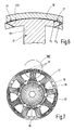
- Fig. 7
- eine Darstellung der Magnetflussverteilung im Stator und Rotor des Synchronmotors in Fig. 1,
- Fig. 8
- eine vergrößerte Darstellung des Ausschnitts VIII in Fig. 7,
- Fig. 9
- eine Draufsicht einer Blechplatine zum Ausstanzen von Blechprofillamellen.
Claims (10)
- Hauptelement für eine elektrische Maschine, insbesondere Stator für einen permanentmagnetisch erregten, elektronisch kommutierten Motor, mit einem hohlzylindrischen Rückschlussjoch (16) mit einer Mehrzahl von in das Rückschlussjoch (16) eingesetzten Polzähnen (17) zur Aufnahme jeweils einer Spule einer elektrischen Wicklung, die jeweils einen Zahnschaft (171), einen gegenüber dem Zahnschaft (171) verbreiterten Zahnkopf (172) und einen Zahnfuß (173) aufweisen, und mit formschlüssigen Presssitzverbindungen zwischen dem Rückschlussjoch (16) und den Polzähnen (17), die jeweils eine im Rückschlussjoch (16) eingeformte Aufnahmenut (20) für einen an den lichten Querschnitt der Aufnahmenut (20) angepassten Zahnfuß (173) aufweisen, dadurch gekennzeichnet, dass in Umfangsrichtung des Rückschlussjochs (16) gesehen die Breite (bf) des Zahnfußes (173) wesentlich größer ist als die Breite (bs) des Zahnschaftes (171).
- Hauptelement nach Anspruch 1, dadurch gekennzeichnet, dass in Umfangsrichtung des Rückschlussjochs (16) gesehen die Breite (bf) des Zahnfußes (173) größer ist als die Breite (bk) des Zahnkopfes (172).
- Hauptelement nach Anspruch 1 oder 2, dadurch gekennzeichnet, dass im Bereich der aneinanderliegenden Fügeflächen von Rückschlussjoch (16) und Zahnfüßen (173) innerhalb jeder Aufnahmenut (20) mindestens ein axial sich erstreckender Luftspalt (21) vorgesehen ist, dessen in Umfangsrichtung gesehene Abmessung kleiner als die Breite (bs) des Zahnschafts (171) ist.
- Hauptelement nach Anspruch 3, dadurch gekennzeichnet, dass die radiale Breite des Luftspalts (21) etwa 0,1 - 0,15 mm beträgt.
- Hauptelement nach Anspruch 3 oder 4, dadurch gekennzeichnet, dass der Luftspalt (21) mittels eines axialen Einstichs im Zahnfuß (173) und/oder im Nutgrund der Aufnahmenut (20) realisiert ist.
- Hauptelement nach Anspruch 5, dadurch gekennzeichnet, dass innerhalb jeder Aufnahmenut (20) drei in Umfangsrichtung voneinander beabstandete Einstiche (22, 23) vorgesehen sind, von denen der mittlere symmetrisch zur radialen Mittellinie des Zahnschafts (171) angeordnet ist.
- Hauptelement nach Anspruch 3 oder 4, dadurch gekennzeichnet, dass in Umfangsrichtung des Rückschlussjochs (16) gesehen in jedem Endbereich innerhalb einer Aufnahmenut (20) ein Luftspalt (21) vorgesehen ist.
- Hauptelement nach Anspruch 7, dadurch gekennzeichnet, dass jeder Endbereich des Zahnfußes (173) einen Krümmungsradius (R2) aufweist, der kleiner ist als der Krümmungsradius (R1) des Nutgrund der Aufnahmenut (20).
- Hauptelement nach einem der Ansprüche 1 - 8, dadurch gekennzeichnet, dass die Presssitzverbindungen Schwalbenschwanzform aufweisen, bei der jeweils ein schwalbenschwanzförmig ausgebildeter Zahnfuß (173) in die einen daran angepassten, schwalbenschwanzförmigen lichten Nutquerschnitt aufweisende Aufnahmenut (20) eingepresst ist.
- Hauptelement nach einem der Ansprüche 1 - 9, dadurch gekennzeichnet, dass das Rückschlussjoch (16) und die Polzähne (17) jeweils aus einer Vielzahl von axial aneinandergereihten Blechprofillamellen (16a, 17a) zusammengesetzt ist und dass eine Blechprofillamelle (16a) des Rückschlussjochs (16) und eine der Anzahl der Polzähne (17) entsprechende Anzahl von Blechprofillamellen (17a) der Polzähne (17) gemeinsam aus einer Blechplatine gestanzt sind.
Applications Claiming Priority (2)
| Application Number | Priority Date | Filing Date | Title |
|---|---|---|---|
| DE10338453 | 2003-08-21 | ||
| DE2003138453 DE10338453A1 (de) | 2003-08-21 | 2003-08-21 | Hauptelement für eine elektrische Maschine |
Publications (3)
| Publication Number | Publication Date |
|---|---|
| EP1508953A2 true EP1508953A2 (de) | 2005-02-23 |
| EP1508953A3 EP1508953A3 (de) | 2006-01-11 |
| EP1508953B1 EP1508953B1 (de) | 2013-05-15 |
Family
ID=34042229
Family Applications (1)
| Application Number | Title | Priority Date | Filing Date |
|---|---|---|---|
| EP20040012968 Expired - Lifetime EP1508953B1 (de) | 2003-08-21 | 2004-06-02 | Hauptelement für eine elektrische Maschine |
Country Status (3)
| Country | Link |
|---|---|
| EP (1) | EP1508953B1 (de) |
| JP (1) | JP2005073490A (de) |
| DE (1) | DE10338453A1 (de) |
Cited By (3)
| Publication number | Priority date | Publication date | Assignee | Title |
|---|---|---|---|---|
| CN108494120A (zh) * | 2018-04-23 | 2018-09-04 | 广东威灵电机制造有限公司 | 直条铁芯、定子铁芯、电机以及定子的绕线方法 |
| DE102021212666A1 (de) | 2021-11-10 | 2023-05-11 | Rolls-Royce Deutschland Ltd & Co Kg | Verfahren zur Montage eines Kühlrohres an einen Polzahn und elektrische Maschine |
| WO2023180139A1 (de) | 2022-03-22 | 2023-09-28 | Zf Friedrichshafen Ag | Statorsegment, statorsegmentanordnung, statorblech, stator und elektromotor |
Families Citing this family (4)
| Publication number | Priority date | Publication date | Assignee | Title |
|---|---|---|---|---|
| JP5253789B2 (ja) | 2007-11-05 | 2013-07-31 | 株式会社ミツバ | ブラシレスモータ |
| JP4998450B2 (ja) | 2008-12-09 | 2012-08-15 | トヨタ自動車株式会社 | ステータの製造方法 |
| JP6649733B2 (ja) * | 2015-09-30 | 2020-02-19 | 日本電産サンキョー株式会社 | ステータ、モータおよびポンプ装置 |
| JPWO2018180448A1 (ja) * | 2017-03-31 | 2020-02-06 | 日本電産株式会社 | ステータ、モータ、電動パワーステアリング装置 |
Citations (3)
| Publication number | Priority date | Publication date | Assignee | Title |
|---|---|---|---|---|
| AT304694B (de) | 1971-07-08 | 1973-01-25 | Gehrig & Co Ag | Verfahren zur Herstellung eines ausgeprägte Pole aufweisenden Stators einer elektrischen Maschine |
| US4912353A (en) | 1987-10-02 | 1990-03-27 | Mitsushita Electric Industrial Co., Ltd. | Two-piece motor stator |
| JP2002036638A (ja) | 2000-07-24 | 2002-02-06 | Ricoh Co Ltd | 出力装置及び印刷装置 |
Family Cites Families (4)
| Publication number | Priority date | Publication date | Assignee | Title |
|---|---|---|---|---|
| JPH02269430A (ja) * | 1989-01-19 | 1990-11-02 | Shinko Electric Co Ltd | 回転電機の凸極回転子 |
| JPH11318059A (ja) * | 1998-05-01 | 1999-11-16 | Harmonic Drive Syst Ind Co Ltd | モータステータの積層鉄心の製造方法 |
| JP2000236638A (ja) * | 1999-02-16 | 2000-08-29 | Hitachi Ltd | 回転電機の固定子 |
| JP3521824B2 (ja) * | 1999-12-17 | 2004-04-26 | 国産電機株式会社 | フライホイールマグネト用ステータ |
-
2003
- 2003-08-21 DE DE2003138453 patent/DE10338453A1/de not_active Withdrawn
-
2004
- 2004-06-02 EP EP20040012968 patent/EP1508953B1/de not_active Expired - Lifetime
- 2004-08-17 JP JP2004237732A patent/JP2005073490A/ja active Pending
Patent Citations (3)
| Publication number | Priority date | Publication date | Assignee | Title |
|---|---|---|---|---|
| AT304694B (de) | 1971-07-08 | 1973-01-25 | Gehrig & Co Ag | Verfahren zur Herstellung eines ausgeprägte Pole aufweisenden Stators einer elektrischen Maschine |
| US4912353A (en) | 1987-10-02 | 1990-03-27 | Mitsushita Electric Industrial Co., Ltd. | Two-piece motor stator |
| JP2002036638A (ja) | 2000-07-24 | 2002-02-06 | Ricoh Co Ltd | 出力装置及び印刷装置 |
Cited By (4)
| Publication number | Priority date | Publication date | Assignee | Title |
|---|---|---|---|---|
| CN108494120A (zh) * | 2018-04-23 | 2018-09-04 | 广东威灵电机制造有限公司 | 直条铁芯、定子铁芯、电机以及定子的绕线方法 |
| DE102021212666A1 (de) | 2021-11-10 | 2023-05-11 | Rolls-Royce Deutschland Ltd & Co Kg | Verfahren zur Montage eines Kühlrohres an einen Polzahn und elektrische Maschine |
| WO2023180139A1 (de) | 2022-03-22 | 2023-09-28 | Zf Friedrichshafen Ag | Statorsegment, statorsegmentanordnung, statorblech, stator und elektromotor |
| DE102022202773A1 (de) | 2022-03-22 | 2023-09-28 | Zf Friedrichshafen Ag | Statorsegment, Statorsegmentanordnung, Statorblech, Stator und Elektromotor |
Also Published As
| Publication number | Publication date |
|---|---|
| EP1508953B1 (de) | 2013-05-15 |
| JP2005073490A (ja) | 2005-03-17 |
| DE10338453A1 (de) | 2005-03-31 |
| EP1508953A3 (de) | 2006-01-11 |
Similar Documents
| Publication | Publication Date | Title |
|---|---|---|
| EP1620932B1 (de) | Elektrische maschine | |
| DE102006021242B4 (de) | Elektromotor | |
| EP1850448A1 (de) | Elektromotor | |
| DE19842948A1 (de) | Elektromotor | |
| EP1609228B1 (de) | Elektrische maschine mit in den stator integrierter rotorlagerung | |
| DE102013211858A1 (de) | Oberflächen- Magnete und vergrabene Magnete für einen Rotor oder Stator einer elektrischen Maschine, der eine Haltegeometrie aufweist | |
| EP1372249A2 (de) | Transversalflussmaschine, insbesondere Unipolar-Transversalflussmaschine | |
| DE112016002076T5 (de) | Rotierende elektrische maschine und verfahren zu ihrer herstellung | |
| DE10133015A1 (de) | Stator mit radialer Wicklung und Verfahren zu seiner Herstellung | |
| DE102009003228B4 (de) | Elektrische Maschine | |
| EP1955426B1 (de) | Elektromaschine und rotor für eine elektromaschine | |
| DE102021205740A1 (de) | Rotor für eine elektrische Maschine, eine elektrische Maschine, sowie Verfahren zum Herstellen eines solchen Rotors | |
| EP1508953B1 (de) | Hauptelement für eine elektrische Maschine | |
| DE102023200313A1 (de) | Rotor einer elektrischen Maschine | |
| DE102007013738A1 (de) | Klauenpolmaschine | |
| EP1850449A2 (de) | Elektromotor | |
| EP0619638A2 (de) | Elektrische Scheibenläufer-Maschine | |
| WO2006084787A1 (de) | Bürstenlose gleichstrommaschine und deren rückschlussringpaket, zahnkranzpaket und kopfteil sowie deren herstellungsverfahren | |
| WO2011088862A1 (de) | Rotor einer elektrischen maschine und verfahren zur herstellung eines rotors einer elektrischen maschine | |
| EP1588470B1 (de) | Elektrische maschine mit permanentmagnet | |
| DE10203272A1 (de) | Rotor für eine elektrische Maschine | |
| DE102024205265A1 (de) | Verfahren zum Herstellen eines Stators, sowie ein Stator und eine elektrische Maschine aufweisend einen solchen Stator | |
| WO2023066686A1 (de) | Verfahren zum herstellen eines stators, insbesondere für einen ec-motor, sowie ein stator und eine elektrische maschine hergestellt nach diesem verfahren | |
| DE3514895A1 (de) | Schrittmotor sowie verfahren zur herstellung | |
| DE102010062385A1 (de) | Ringförmiger Permanentmagnet in einer elektrischen Maschine |
Legal Events
| Date | Code | Title | Description |
|---|---|---|---|
| PUAI | Public reference made under article 153(3) epc to a published international application that has entered the european phase |
Free format text: ORIGINAL CODE: 0009012 |
|
| AK | Designated contracting states |
Kind code of ref document: A2 Designated state(s): AT BE BG CH CY CZ DE DK EE ES FI FR GB GR HU IE IT LI LU MC NL PL PT RO SE SI SK TR |
|
| AX | Request for extension of the european patent |
Extension state: AL HR LT LV MK |
|
| PUAL | Search report despatched |
Free format text: ORIGINAL CODE: 0009013 |
|
| AK | Designated contracting states |
Kind code of ref document: A3 Designated state(s): AT BE BG CH CY CZ DE DK EE ES FI FR GB GR HU IE IT LI LU MC NL PL PT RO SE SI SK TR |
|
| AX | Request for extension of the european patent |
Extension state: AL HR LT LV MK |
|
| 17P | Request for examination filed |
Effective date: 20060711 |
|
| AKX | Designation fees paid |
Designated state(s): CZ DE FR IT SE |
|
| 17Q | First examination report despatched |
Effective date: 20070823 |
|
| GRAP | Despatch of communication of intention to grant a patent |
Free format text: ORIGINAL CODE: EPIDOSNIGR1 |
|
| GRAS | Grant fee paid |
Free format text: ORIGINAL CODE: EPIDOSNIGR3 |
|
| GRAJ | Information related to disapproval of communication of intention to grant by the applicant or resumption of examination proceedings by the epo deleted |
Free format text: ORIGINAL CODE: EPIDOSDIGR1 |
|
| GRAP | Despatch of communication of intention to grant a patent |
Free format text: ORIGINAL CODE: EPIDOSNIGR1 |
|
| GRAS | Grant fee paid |
Free format text: ORIGINAL CODE: EPIDOSNIGR3 |
|
| GRAA | (expected) grant |
Free format text: ORIGINAL CODE: 0009210 |
|
| AK | Designated contracting states |
Kind code of ref document: B1 Designated state(s): CZ DE FR IT SE |
|
| REG | Reference to a national code |
Ref country code: DE Ref legal event code: R096 Ref document number: 502004014162 Country of ref document: DE Effective date: 20130711 |
|
| PG25 | Lapsed in a contracting state [announced via postgrant information from national office to epo] |
Ref country code: SE Free format text: LAPSE BECAUSE OF FAILURE TO SUBMIT A TRANSLATION OF THE DESCRIPTION OR TO PAY THE FEE WITHIN THE PRESCRIBED TIME-LIMIT Effective date: 20130515 |
|
| PG25 | Lapsed in a contracting state [announced via postgrant information from national office to epo] |
Ref country code: CZ Free format text: LAPSE BECAUSE OF FAILURE TO SUBMIT A TRANSLATION OF THE DESCRIPTION OR TO PAY THE FEE WITHIN THE PRESCRIBED TIME-LIMIT Effective date: 20130515 |
|
| PG25 | Lapsed in a contracting state [announced via postgrant information from national office to epo] |
Ref country code: IT Free format text: LAPSE BECAUSE OF FAILURE TO SUBMIT A TRANSLATION OF THE DESCRIPTION OR TO PAY THE FEE WITHIN THE PRESCRIBED TIME-LIMIT Effective date: 20130515 |
|
| PLBE | No opposition filed within time limit |
Free format text: ORIGINAL CODE: 0009261 |
|
| STAA | Information on the status of an ep patent application or granted ep patent |
Free format text: STATUS: NO OPPOSITION FILED WITHIN TIME LIMIT |
|
| 26N | No opposition filed |
Effective date: 20140218 |
|
| REG | Reference to a national code |
Ref country code: DE Ref legal event code: R097 Ref document number: 502004014162 Country of ref document: DE Effective date: 20140218 |
|
| REG | Reference to a national code |
Ref country code: FR Ref legal event code: PLFP Year of fee payment: 13 |
|
| PGFP | Annual fee paid to national office [announced via postgrant information from national office to epo] |
Ref country code: FR Payment date: 20160621 Year of fee payment: 13 |
|
| PGFP | Annual fee paid to national office [announced via postgrant information from national office to epo] |
Ref country code: DE Payment date: 20160810 Year of fee payment: 13 |
|
| REG | Reference to a national code |
Ref country code: DE Ref legal event code: R119 Ref document number: 502004014162 Country of ref document: DE |
|
| REG | Reference to a national code |
Ref country code: FR Ref legal event code: ST Effective date: 20180228 |
|
| PG25 | Lapsed in a contracting state [announced via postgrant information from national office to epo] |
Ref country code: DE Free format text: LAPSE BECAUSE OF NON-PAYMENT OF DUE FEES Effective date: 20180103 |
|
| PG25 | Lapsed in a contracting state [announced via postgrant information from national office to epo] |
Ref country code: FR Free format text: LAPSE BECAUSE OF NON-PAYMENT OF DUE FEES Effective date: 20170630 |