EP1509176B1 - Chambre a pression pulsatoire dans un membre prothetique - Google Patents
Chambre a pression pulsatoire dans un membre prothetique Download PDFInfo
- Publication number
- EP1509176B1 EP1509176B1 EP03755478A EP03755478A EP1509176B1 EP 1509176 B1 EP1509176 B1 EP 1509176B1 EP 03755478 A EP03755478 A EP 03755478A EP 03755478 A EP03755478 A EP 03755478A EP 1509176 B1 EP1509176 B1 EP 1509176B1
- Authority
- EP
- European Patent Office
- Prior art keywords
- pressure
- socket
- residuum
- chamber
- limb
- Prior art date
- Legal status (The legal status is an assumption and is not a legal conclusion. Google has not performed a legal analysis and makes no representation as to the accuracy of the status listed.)
- Expired - Lifetime
Links
- ATQUFXWBVZUTKO-UHFFFAOYSA-N CC1=CCCC1 Chemical compound CC1=CCCC1 ATQUFXWBVZUTKO-UHFFFAOYSA-N 0.000 description 1
Images






Classifications
-
- A—HUMAN NECESSITIES
- A61—MEDICAL OR VETERINARY SCIENCE; HYGIENE
- A61H—PHYSICAL THERAPY APPARATUS, e.g. DEVICES FOR LOCATING OR STIMULATING REFLEX POINTS IN THE BODY; ARTIFICIAL RESPIRATION; MASSAGE; BATHING DEVICES FOR SPECIAL THERAPEUTIC OR HYGIENIC PURPOSES OR SPECIFIC PARTS OF THE BODY
- A61H9/00—Pneumatic or hydraulic massage
- A61H9/005—Pneumatic massage
- A61H9/0078—Pneumatic massage with intermittent or alternately inflated bladders or cuffs
-
- A—HUMAN NECESSITIES
- A61—MEDICAL OR VETERINARY SCIENCE; HYGIENE
- A61F—FILTERS IMPLANTABLE INTO BLOOD VESSELS; PROSTHESES; DEVICES PROVIDING PATENCY TO, OR PREVENTING COLLAPSING OF, TUBULAR STRUCTURES OF THE BODY, e.g. STENTS; ORTHOPAEDIC, NURSING OR CONTRACEPTIVE DEVICES; FOMENTATION; TREATMENT OR PROTECTION OF EYES OR EARS; BANDAGES, DRESSINGS OR ABSORBENT PADS; FIRST-AID KITS
- A61F2/00—Filters implantable into blood vessels; Prostheses, i.e. artificial substitutes or replacements for parts of the body; Appliances for connecting them with the body; Devices providing patency to, or preventing collapsing of, tubular structures of the body, e.g. stents
- A61F2/50—Prostheses not implantable in the body
- A61F2/68—Operating or control means
- A61F2/74—Operating or control means fluid, i.e. hydraulic or pneumatic
-
- A—HUMAN NECESSITIES
- A61—MEDICAL OR VETERINARY SCIENCE; HYGIENE
- A61F—FILTERS IMPLANTABLE INTO BLOOD VESSELS; PROSTHESES; DEVICES PROVIDING PATENCY TO, OR PREVENTING COLLAPSING OF, TUBULAR STRUCTURES OF THE BODY, e.g. STENTS; ORTHOPAEDIC, NURSING OR CONTRACEPTIVE DEVICES; FOMENTATION; TREATMENT OR PROTECTION OF EYES OR EARS; BANDAGES, DRESSINGS OR ABSORBENT PADS; FIRST-AID KITS
- A61F2/00—Filters implantable into blood vessels; Prostheses, i.e. artificial substitutes or replacements for parts of the body; Appliances for connecting them with the body; Devices providing patency to, or preventing collapsing of, tubular structures of the body, e.g. stents
- A61F2/50—Prostheses not implantable in the body
- A61F2/78—Means for protecting prostheses or for attaching them to the body, e.g. bandages, harnesses, straps, or stockings for the limb stump
- A61F2/80—Sockets, e.g. of suction type
-
- A—HUMAN NECESSITIES
- A61—MEDICAL OR VETERINARY SCIENCE; HYGIENE
- A61H—PHYSICAL THERAPY APPARATUS, e.g. DEVICES FOR LOCATING OR STIMULATING REFLEX POINTS IN THE BODY; ARTIFICIAL RESPIRATION; MASSAGE; BATHING DEVICES FOR SPECIAL THERAPEUTIC OR HYGIENIC PURPOSES OR SPECIFIC PARTS OF THE BODY
- A61H9/00—Pneumatic or hydraulic massage
- A61H9/005—Pneumatic massage
-
- A—HUMAN NECESSITIES
- A61—MEDICAL OR VETERINARY SCIENCE; HYGIENE
- A61H—PHYSICAL THERAPY APPARATUS, e.g. DEVICES FOR LOCATING OR STIMULATING REFLEX POINTS IN THE BODY; ARTIFICIAL RESPIRATION; MASSAGE; BATHING DEVICES FOR SPECIAL THERAPEUTIC OR HYGIENIC PURPOSES OR SPECIFIC PARTS OF THE BODY
- A61H9/00—Pneumatic or hydraulic massage
- A61H9/005—Pneumatic massage
- A61H9/0071—Pneumatic massage by localized pressure, e.g. air streams or jets
-
- A—HUMAN NECESSITIES
- A61—MEDICAL OR VETERINARY SCIENCE; HYGIENE
- A61F—FILTERS IMPLANTABLE INTO BLOOD VESSELS; PROSTHESES; DEVICES PROVIDING PATENCY TO, OR PREVENTING COLLAPSING OF, TUBULAR STRUCTURES OF THE BODY, e.g. STENTS; ORTHOPAEDIC, NURSING OR CONTRACEPTIVE DEVICES; FOMENTATION; TREATMENT OR PROTECTION OF EYES OR EARS; BANDAGES, DRESSINGS OR ABSORBENT PADS; FIRST-AID KITS
- A61F2/00—Filters implantable into blood vessels; Prostheses, i.e. artificial substitutes or replacements for parts of the body; Appliances for connecting them with the body; Devices providing patency to, or preventing collapsing of, tubular structures of the body, e.g. stents
- A61F2/50—Prostheses not implantable in the body
- A61F2/78—Means for protecting prostheses or for attaching them to the body, e.g. bandages, harnesses, straps, or stockings for the limb stump
- A61F2/7812—Interface cushioning members placed between the limb stump and the socket, e.g. bandages or stockings for the limb stump
- A61F2/7843—Inflatable bladders
-
- A—HUMAN NECESSITIES
- A61—MEDICAL OR VETERINARY SCIENCE; HYGIENE
- A61F—FILTERS IMPLANTABLE INTO BLOOD VESSELS; PROSTHESES; DEVICES PROVIDING PATENCY TO, OR PREVENTING COLLAPSING OF, TUBULAR STRUCTURES OF THE BODY, e.g. STENTS; ORTHOPAEDIC, NURSING OR CONTRACEPTIVE DEVICES; FOMENTATION; TREATMENT OR PROTECTION OF EYES OR EARS; BANDAGES, DRESSINGS OR ABSORBENT PADS; FIRST-AID KITS
- A61F2/00—Filters implantable into blood vessels; Prostheses, i.e. artificial substitutes or replacements for parts of the body; Appliances for connecting them with the body; Devices providing patency to, or preventing collapsing of, tubular structures of the body, e.g. stents
- A61F2/50—Prostheses not implantable in the body
- A61F2002/5016—Prostheses not implantable in the body adjustable
- A61F2002/5032—Prostheses not implantable in the body adjustable for adjusting fluid pressure
-
- A—HUMAN NECESSITIES
- A61—MEDICAL OR VETERINARY SCIENCE; HYGIENE
- A61F—FILTERS IMPLANTABLE INTO BLOOD VESSELS; PROSTHESES; DEVICES PROVIDING PATENCY TO, OR PREVENTING COLLAPSING OF, TUBULAR STRUCTURES OF THE BODY, e.g. STENTS; ORTHOPAEDIC, NURSING OR CONTRACEPTIVE DEVICES; FOMENTATION; TREATMENT OR PROTECTION OF EYES OR EARS; BANDAGES, DRESSINGS OR ABSORBENT PADS; FIRST-AID KITS
- A61F2/00—Filters implantable into blood vessels; Prostheses, i.e. artificial substitutes or replacements for parts of the body; Appliances for connecting them with the body; Devices providing patency to, or preventing collapsing of, tubular structures of the body, e.g. stents
- A61F2/50—Prostheses not implantable in the body
- A61F2/68—Operating or control means
- A61F2/70—Operating or control means electrical
- A61F2002/704—Operating or control means electrical computer-controlled, e.g. robotic control
-
- A—HUMAN NECESSITIES
- A61—MEDICAL OR VETERINARY SCIENCE; HYGIENE
- A61F—FILTERS IMPLANTABLE INTO BLOOD VESSELS; PROSTHESES; DEVICES PROVIDING PATENCY TO, OR PREVENTING COLLAPSING OF, TUBULAR STRUCTURES OF THE BODY, e.g. STENTS; ORTHOPAEDIC, NURSING OR CONTRACEPTIVE DEVICES; FOMENTATION; TREATMENT OR PROTECTION OF EYES OR EARS; BANDAGES, DRESSINGS OR ABSORBENT PADS; FIRST-AID KITS
- A61F2/00—Filters implantable into blood vessels; Prostheses, i.e. artificial substitutes or replacements for parts of the body; Appliances for connecting them with the body; Devices providing patency to, or preventing collapsing of, tubular structures of the body, e.g. stents
- A61F2/50—Prostheses not implantable in the body
- A61F2/78—Means for protecting prostheses or for attaching them to the body, e.g. bandages, harnesses, straps, or stockings for the limb stump
- A61F2/80—Sockets, e.g. of suction type
- A61F2002/802—Suction sockets, i.e. utilizing differential air pressure to retain the prosthesis on the stump
-
- A—HUMAN NECESSITIES
- A61—MEDICAL OR VETERINARY SCIENCE; HYGIENE
- A61F—FILTERS IMPLANTABLE INTO BLOOD VESSELS; PROSTHESES; DEVICES PROVIDING PATENCY TO, OR PREVENTING COLLAPSING OF, TUBULAR STRUCTURES OF THE BODY, e.g. STENTS; ORTHOPAEDIC, NURSING OR CONTRACEPTIVE DEVICES; FOMENTATION; TREATMENT OR PROTECTION OF EYES OR EARS; BANDAGES, DRESSINGS OR ABSORBENT PADS; FIRST-AID KITS
- A61F2/00—Filters implantable into blood vessels; Prostheses, i.e. artificial substitutes or replacements for parts of the body; Appliances for connecting them with the body; Devices providing patency to, or preventing collapsing of, tubular structures of the body, e.g. stents
- A61F2/50—Prostheses not implantable in the body
- A61F2/78—Means for protecting prostheses or for attaching them to the body, e.g. bandages, harnesses, straps, or stockings for the limb stump
- A61F2/80—Sockets, e.g. of suction type
- A61F2002/802—Suction sockets, i.e. utilizing differential air pressure to retain the prosthesis on the stump
- A61F2002/805—Suction sockets, i.e. utilizing differential air pressure to retain the prosthesis on the stump having an air valve
-
- A—HUMAN NECESSITIES
- A61—MEDICAL OR VETERINARY SCIENCE; HYGIENE
- A61H—PHYSICAL THERAPY APPARATUS, e.g. DEVICES FOR LOCATING OR STIMULATING REFLEX POINTS IN THE BODY; ARTIFICIAL RESPIRATION; MASSAGE; BATHING DEVICES FOR SPECIAL THERAPEUTIC OR HYGIENIC PURPOSES OR SPECIFIC PARTS OF THE BODY
- A61H2201/00—Characteristics of apparatus not provided for in the preceding codes
- A61H2201/50—Control means thereof
- A61H2201/5007—Control means thereof computer controlled
-
- A—HUMAN NECESSITIES
- A61—MEDICAL OR VETERINARY SCIENCE; HYGIENE
- A61H—PHYSICAL THERAPY APPARATUS, e.g. DEVICES FOR LOCATING OR STIMULATING REFLEX POINTS IN THE BODY; ARTIFICIAL RESPIRATION; MASSAGE; BATHING DEVICES FOR SPECIAL THERAPEUTIC OR HYGIENIC PURPOSES OR SPECIFIC PARTS OF THE BODY
- A61H9/00—Pneumatic or hydraulic massage
- A61H9/0007—Pulsating
Definitions
- Residual limbs come in various sizes and shapes with respect to the stump. That is, most new amputations are either slightly bulbous or cylindrical in shape while older amputations that may have had a lot of atrophy are generally more conical in shape. Residual limbs may further be characterized by their various individual problems or configurations including the volume and shape of a stump and possible scar, skin graft, bony prominence, uneven limb volume, neuroma, pain, edema or soft tissue configurations.
- amputees who have lost a part of their arm 26, which terminates in a stump 28 also may be characterized as having vascular routes, nerve bundles as well as soft and bony tissues.
- the residual limb 10 includes the humerus bone 30 which extends from below the shoulder to the elbow from which the radius 34 and ulna 36 bones may pivotally extend to the point of severance.
- the humerus bone 30 are the biceps muscle 38 and the triceps muscle 40 which still yet may be connected to the radius 34 and the ulna, 36, respectively.
- Sleeve suspensions were also used wherein the amputee may use a latex rubber tube which forms into a rubber-like sleeve which would be rolled on over both the top of the artificial limb and onto the amputee's thigh.
- the sleeve suspensions have been used in combination with other forms of suspensions techniques.
- the negative pressure aspects have been utilized for a closed chamber in that a socket is donned by pulling in with a sock, pulling the sock out of the socket and then closing the opening with a valve. This creates a seal at the bottom and the stump is held into the socket by the hypobaric seal.
- an improved artificial limb that will offer a total or substantially total contact relationship with the residual limb; absorb and dissipate shock, mechanical and shear forces typically associated with ambulation, twisting and turning and weight bearing with an artificial limb; control residual limb volume by way of even force distribution; use negative pressure as a locking device to hold the residual limb into the socket without causing swelling of the residual limb into the socket; and control residual limb volume changes by a negative pressure system.
- the pressure control system should be automatically regulated.
- fluid management within a residual limb becomes a problem during the wearing of a prosthetic device by an amputee. Loss of fluid from the residual limb can occur during the course of a day or over a longer period of time, causing fit problems with the prosthetic device.
- prosthetic devices may also cause swelling and edema problems in residual limbs due to pooling of fluid. The effects of pressure, both positive and negative, within the prosthesis may compound these potential problems.
- amputees also encounter vascular flow problems in the residual limb resulting in additional amputation of limb material. Sometimes these vascular problems are the reason for the amputation in the first place. Such vascular problems may cause wounds within the residual limb, or may inhibit proper healing of wounds within the residual limb obtained for any reason.
- U.S. Patent No. 5,658,353 discloses a method for donning or doffing a suction suspension prosthesis.
- an air tight seal is provided between the residual limb and a suction socket.
- a modified valve is installed to the suction socket and the air pressure is decreased to draw the residual limb into the suction socket.
- the modified air valve is replaced by a regular valve and there is no connection to a negative pressure source when the prosthesis is worn in use.
- a modified valve is installed to the suction socket and a positive pressure source is connected to the modified valve so as to increase the air pressure within the socket.
- the air injected into the socket serves to push the limb from the socket avoiding a painful or injurious doffing of the prosthesis.
- a principal object and advantage of the present invention is that increases blood flow to a body part.
- the drawings show a number of different embodiments of an apparatus and method for managing the volume of fluid in a residual limb joined to an artificial limb, by applying a vacuum source to the artificial limb cavity or chamber. It will be seen that application of the vacuum to the cavity can draw the residual limb (which may be encased in a liner) firmly and totally against the socket, thereby preventing or reducing swelling of the residual limb into the socket, because there is little or no open chamber into which the residual limb may be drawn by the vacuum. Importantly, application of the vacuum to the cavity also opposes the loss of fluids from the residual limb due to weight-bearing pressures.
- Figs. 3 and 4 show one embodiment of the apparatus 50 of the present invention.
- the artificial limb 50 includes an outer socket 52, shin 54, and foot 56.
- the outer socket 52 has a volume and shape to receive a substantial portion of the residual limb 14 with a space 58 or chamber therebetween.
- the artificial limb 50 may also include a stretchable nylon second sleeve 94 for rolling over and covering the suspension sleeve 86 to prevent clothing from sticking to and catching the suspension sleeve 86.
- the amputee can take the stretchable nylon second sleeve 94, suitably made of a spandex-like material and roll it up over the stump 14 to the upper portions of the residual limb suitably as the thigh of a leg 12.
- the polyurethane sleeve 86 can also be rolled upwardly over the residual limb 10.
- the liner 92 is optionally donned.
- the polyurethane sleeve 86 is tacky. Consequently, the stretchable nylon second sleeve 94 may be utilized and rolled over the polyurethane sleeve 86.
- the regulator means 80 may control the positive air pressure source 100 to cause air pressure to compress the inner socket 60A to compensate for the decreased volume of the residual limb, as shown in Fig. 6.
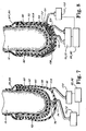
- FIG. 7 A third example of the artificial limb 50 is shown in Fig. 7.
- the third embodiment can be considered a combination of the first and second embodiments described above.
- a device such as a mechanical motor-driven pump 72 may act as both the vacuum source 70 and the positive air pressure source 100.
- the regulator means 80, vacuum source 70 and positive air pressure source 100 are connected to a power source (not shown), which may be a battery.
- the vacuum source 70 under control of the regulator means 80, will compensate for reduced residual limb volume up to a certain point. From that point on, the regulator means 80 will cause the positive air pressure source 100 to further compensate for reduced residual limb volume as described above.
- the third embodiment thus uses both vacuum and positive air pressure working together to lock the residual limb 14 into the inner socket 60 and reduce socket volume to compensate for fluid loss in the residual limb 14.
- the exact point at which the changeover is made between vacuum compensation and positive air pressure compensation can be controlled by the regulator means 80, which as described may be a computer appropriately programmed for the socket environment.
- the amputee proceeds as described above. After inserting the residual limb 14 (with optional coverings) into the inner socket 60B, which is both compressible and expandable, and rolling the suspension sleeve 86 over the outer socket 52, the amputee activates the regulator means 80, causing the vacuum source 70 to apply a vacuum to the space 58. This causes the material 108 to lock mechanically together into a rigid mass, conforming to the shape of the residual limb 14.
- the inner socket 60B may expand slightly under the weight of the residual limb 14 and under the influence of vacuum.
- the fourth example may also include a positive air pressure source 100 as previously described, to adjust the size of the inner socket 60B to compensate for decreased residual limb volume.
- the fifth example also includes the seal or seal means 84 which preferably consists of a non-foamed, nonporous polyurethane suspension sleeve 86 for rolling over and covering a portion of the residual limb 14. A portion of the seal means 86 is adapted to be disposed between the outer socket 52 and the inner socket 60.
- the sleeve may be made, for example, of any of a variety of air-impervious elastomers.
- FIG. 11 A sixth example of the apparatus of the present invention is shown in Figs. 11 and 12.
- the sixth embodiment can be considered a variation of the first embodiment shown in Fig. 4.
- the extension may be any sort of protrusion from the inner socket, such as a bulge or tab.
- the extension 104 comprises a shuttle pin 108.
- the locking mechanism may be any sort of member which engages both the extension 104 and the docking device 106, such as a screw, wire, or pin.
- the locking mechanism 105 comprises a second pin 110 which extends outside the outer socket 52 as to be accessible.
- the sixth embodiment includes two thin sheaths, rather than one.
- a first inner sheath 90 may preferably be disposed between the residual limb 14 and the inner surface 64 of the inner socket 60. As vacuum is applied to the cavity 62, the inner sheath 90 will allow the vacuum to be evenly applied throughout the cavity 62. Without the inner sheath 90, the residual limb 14 might "tack up" against the inner surface 64 and form a seal which might prevent even application of the vacuum to the cavity 62.
- the inner sheath 90 may also be used to assist the amputee into a smooth and easy fitting into the inner socket 60.
- the suspension sleeve 86 goes between the inner socket 60 and the outer socket 52, so that the sleeve 86 is protected from damage.
- a vacuum valve 74 is placed between the cavity 62 and the vacuum source 70 to maintain vacuum in the cavity 62.
- the vacuum valve 74 is a one-way valve or non-return valve.
- the vacuum source 70, vacuum tube 76, vacuum valve 74, regulator means 80, and power source 83 are all attached to the outer socket 52 in the space 58 between the outer socket 52 and inner socket 60. In this way, these delicate components are protected against being damaged by impact. Because of the placement of the regulator means 80 within the outer socket 52, a vacuum control 77 is provided extending outside the outer socket 52 to allow manual control of the regulator means 80.
- the mechanical interlock 103 does not engage the inner socket 60. Instead, the mechanical interlock engages the outer socket 52 and the suspension sleeve 86.
- the suspension sleeve 86 covers the entire inner socket 60, and the suspension sleeve 86 has the extension 104 or shuttle pin 108 embedded in the suspension sleeve at the distal end of the suspension sleeve, as shown in Fig. 14.
- the extension 104 has a portion 104A embedded in the suspension sleeve. This portion 104A may be a disk or umbrella 104A. The extension 104 then engages the docking device 106 as previously described.
- the suspension sleeve 86 is modified to support the additional weight imposed on the suspension sleeve 86 due to the outer socket 52 and artificial limb.
- the suspension sleeve 86 is fabricated from a material which allows circumferential expansion but resists longitudinal stretching under the weight of the artificial limb. Such a material is described in U.S. Pat. No. 5,571,208.
- the sleeve 86 preferably contains fabric threads which may be oriented circumferentially around the sleeve.
- the threads preferably are comprised of double-knit polyurethane.
- the threads may also include nylon.
- the threads permit the sleeve 86 to expand circumferentially so that the sleeve may be slipped onto the residual limb 14 and so that the lower portion may be slipped over the inner socket 52.
- the threads are preferably connected together with cross-links, which also may be preferably comprised of polyurethane.
- the cross-links and threads form a matrix which allows circumferential expansion but resists longitudinal stretching under the weight of the artificial limb.
- the sleeve 86 may have at or about a 4-to-1 ratio of circumferential stretch relative to longitudinal stretch.
- the sleeve 86 may have a portion above the inner socket 52 which is manufactured of material which allows both vertical and horizontal stretching, to increase flexibility.
- FIG. 15 An eighth example of the artificial limb of the present invention is shown in Fig. 15.
- a vacuum source 70 is connected to the cavity 62 by a vacuum valve 78, thereby drawing the residual limb 14 into firm contact with the socket 60.
- a ninth embodiment of the artificial limb 50 is shown in Fig. 16.
- the ninth example is the same as the eighth embodiment, but a vacuum reservoir 110 is added between the vacuum source 70 and the vacuum valve 78.
- the vacuum reservoir 110 has a volume substantially larger than the cavity 62.
- the vacuum reservoir may have a volume of about 2 gallons or about 9000 cc while the volume of the cavity 62 is preferably about 100 cc or even less.
- the vacuum source 70 may be activated to restore vacuum to the vacuum reservoir 110.
- the vacuum source 70 may be activated either manually or by a regulator (not shown).
- An inner sheath 90 may be adapted to be disposed between the liner 92 and the socket, to ensure even distribution of vacuum in the cavity 62, as earlier described.
- the inner sheath 90 may be thin knitted nylon.
- the sheath 90 may also be affixed to the outside of the liner 92.
- the seal means 84 is preferably a nonfoamed, nonporous polyurethane suspension sleeve 86 for rolling over and covering the socket 60 and a portion of the artificial limb 14, as earlier described.
- a stretchable nylon second sleeve 94 for rolling over and covering the suspension sleeve 86 may be added to prevent clothing from sticking to and catching on the suspension sleeve 86, as earlier described.
- the vacuum source 70 is preferably a motor or mechanical driven vacuum pump 72, as earlier described.
- a vacuum tube 76 may be necessary to connect the vacuum pump 72 to the vacuum valve 78, depending on the placement of the vacuum pump 72.
- the vacuum source 70 may also be a weight-actuated vacuum pump and shock absorber as disclosed in U.S. Patent No. 6,554,868.
- a regulator means 80 a vacuum reservoir 110, or a weight-actuated vacuum pump and shock absorber as disclosed in U.S. Patent No. 6,554,868, may be employed.
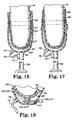
- Fig. 17 shows one solution to this problem.
- the liner 92 is improved by adding an annular seal 140 extending outwardly from the fabric cover 130.
- the annular seal which may be made from the same material as the inner layer 92 of the liner, is adapted to sealingly engage the suspension sleeve 86, producing a seal against the vacuum in cavity 62 at the point of contact with the suspension sleeve 86. Therefore, the vacuum in cavity 62 now draws against the annular seal 130 rather than against the skin of the residual limb 14.
- annular seal 140 does not make contact with the suspension sleeve 86, but rather makes contact with the inner wall 63 of the socket 60, and makes a seal at that point. No suspension sleeve is used in this variation, it being found that sufficient holding force is provided by the vacuum in cavity 62.
- the invention of Fig. 19 also preferably includes a locking mechanism seal 150 adapted to engage the inner wall 63 of the socket 60 about the locking mechanism 105.
- the seal 150 could alternatively be on the outer surface of the socket 60.
- FIG. 20 Another alternative is shown in Fig. 20.
- the fabric cover 130 stops below the annular seal 140.
- the annular seal 140 may also be made 5 of the same material as the liner 92.
- a very important advantage is the use of vacuum within the socket to prevent fluids from migrating out of the distal end of the residual limb due to weight-bearing pressures, or at least to reduce this migration.
- a vacuum to the socket cavity 62 can suck the liner 92 against the inner wall of the socket 60.
- the liner can be relatively snug against the residual limb 14 so that the residual limb can be butted up against the inner wall of the socket.
- the wearer's body weight can force the limb and liner more tightly against the inner wall of the socket.
- the weight of the artificial limb will have a tendency to cause the socket 60 to pull away from the liner 92. This is prevented or reduced by the vacuum in the socket cavity.
- the vacuum in the socket cavity 62 is preferably at least about 25 - 63 cm (10 to 25 inches) of mercury At this level of vacuum, it has been found with some wearers that the residual limb loses only about 1 % of its volume during the day.
- the apparatus 210 preferably comprises a sealed chamber 212 having an interior 214 with a pressure line 216 entering the interior 214.
- the pressure line 216 is connected to a control device 218.
- the control device 218 is, in turn, connected to a positive pressure source 220 and a negative pressure source 222.
- a positive pressure source 220 and a negative pressure source 222 Although shown as separate positive and negative pressure sources, 220, 222, it is to be understood that a single pressure source capable of providing both positive and negative pressures may also be used.
- This configuration reduces the overall volume of the chamber as compared to prior pressure chambers usually formed as large boxes into which a body part is placed.
- Reduced volume of the chamber 212 results in enhanced control over the fluid volume in the body part P, thereby reducing the occurrence or degree of edema, the accumulation of fluid in a body part.
- Better control over fluid volume provides more variability in the time and amount of pressure therapy that may be applied to the body part, without causing or at least reducing negative side effects. That is, a smaller volume chamber, such as chamber 212, can allow for longer pressure therapy sessions or overall duration without causing or at least reducing significant edema or other problems for the patient.
- the chamber 212 can be said to provide a means for applying pressure to the portion of the body or body part P.
- the liner 224 can extend over the body part P and beyond the boundaries of the chamber 212, such that the chamber 212 can seal to the liner 224 and not to the body part P directly, as shown in Fig. 21.
- the positive and negative pressure can be applied to the liner 224 and not the skin of the patient.
- Use of the liner 224 such as a urethane liner, allows for equalization of the pressure being applied (both positive and negative).
- Certain urethane liners are known to be semi-fluid and allow for the distribution or re-distribution of force over the surface area of the urethane liner. As a result, the body part P is subjected to less trauma and thus more beneficial pressure therapy may be provided.
- the liner 224 can be said to provide a means for sealing and/or a means for equalizing, distributing, or redistributing pressure.
- a pneumatic connection 300 can be coupled to the positive pressure source 220 and is controlled by a normally closed electronic solenoid 302.
- the pneumatic connection 300 can also be coupled to the negative pressure source 222 and is controlled by a normally closed electronic solenoid 304.
- the pneumatic connection 300 can be coupled to the chamber 212 via a second connection 310, in which an absolute pressure sensor 312 and a bleed to atmosphere 314 can be fluidly coupled.
- the absolute pressure sensor 312 can be configured to sense both positive and negative pressures.
- the bleed to atmosphere 314, as shown, can also be a normally closed electronic solenoid.
- Computer or other programmable control of the solenoids 302, 304, 314 and sensor 312 provide the desired pressure cycles within the chamber 212, as well as better optimization, increased control of the pressure chamber and pressure therapy, and feedback capability. All or portions of the components noted in this paragraph can be referred to as means for controlling pressure.
- a representative pressure control flow chart is shown in Fig. 23.
- the pressure of the chamber 212 can be checked in step 350.
- the pressure can then be compared to a desired targeted value and evaluated as to whether the sensed pressure is above the targeted value, in step 355. If above, the negative pressure solenoid 204 can be opened, in step 358. The pressure can then be checked again in step 350. If not above, the sensed pressure can be evaluated as to whether it is below the targeted value, in step 360. If below, the positive pressure solenoid 302 can be opened, in step 362. The pressure can then be checked again in step 350. If not below, the pressure can be checked again in step 350. This loop can be repeated as needed during the pressure therapy session.
- the positive and negative pressure is applied to the body part P in a wave cycle (preferably a sine wave).
- This wave could be altered or possibly synchronized to the rhythm of the heart to assist in blood flow.
- the control device 218 can be coupled to a heart rate monitor or other sensor allowing for feedback to the control device 218 in order to synchronize the pressure wave cycle to the rhythm of the heart of the patient or the blood flow in the particular body part being treated.
- a volume of blood can be evacuated from the body part P in the area inside the chamber.
- a volume of blood is pulled into the body part P in the area in the chamber. Since blood can flow only in one direction in a blood vessel of the human body, this is intended to provide a fresh supply of blood to the body part P in the area inside the chamber.
- the apparatus may comprise a bandage or patch that makes a sealed contact with an area of the skin, rather than a chamber into which a body part is inserted.
- a liner portion is provided as part of the bandage or patch over the skin with the pressure portion applied to the liner portion, instead of directly to the skin.
- the bandage or patch can be attachable by an adhesive or by another fastening mechanism.
- Figs. 24 and 25 show the relationship between measured blood flow 400 in the body part and the pressure cycle 410 applied to the body part.
- a positive pressure 412 can be applied, blood flow increases 402 until the positive pressure constricts the vessels or significantly reduces the fluid volume in the body, thus causing blood flow to drop 404.
- the subsequent application of a negative pressure 414 results in another increase in blood flow 406, but only to a limit at which time the blood flow again drops off 408. This cycle is repeated as the positive and negative pressures are repeated.
- blood flow is generally increased during the pressure therapy.
- the range of pressures that the apparatus may employ is from at or about 30 to at or about 760 mm.
- FIG. 26 a simplified schematic of a first embodiment of a therapeutic artificial limb for amputees is shown.
- a residual limb 502 of a wearer is received within a socket 504.
- the residual limb 502 is covered by a liner 506.
- a chamber 505 is formed between the residual limb 502 and the socket 504.
- An over sleeve 508 may be worn to cover the residual limb 502 and socket 504, along with other inner sleeves and stockings, as described above but not shown for clarity.
- the socket 504 is coupled to a pylon 510, or other structural member forming the artificial limb 500, as needed, and a foot 512.
- the artificial limb 500 may include a knee joint, an elbow joint, a hand, or connections thereto, or any other appropriate components based on the extremity that was amputated and the needs of the wearer.
- the components coupled to the socket 504 may also be known as a prosthesis, a prosthetic device or a prosthetic limb. Details of the various connections possible between the prosthesis and socket 504 are described above or in other appropriate literature.
- a control device 520 connects to the chamber 505 within the socket 504 via a supply line 522.
- the control device 520 also connects to either a positive pressure source 524, a negative pressure source 526, or both, depending on the desired output of the therapeutic artificial limb 500.
- the control device 520 may be connected to a single pressure source configured to provide both negative and positive pressures.
- the connection 522 to the socket 504 may include a fitting 523 configured to appropriately connect and seal the connection 522.
- the fitting 523 may include a quick release coupling, a mechanical fastener, an adhesive, a valve, or other necessary device usable for a pressure line connection.
- the control device 520 and pressure source or sources 524, 526 may be provided in conjunction with the pylon 510, such as mounted to the pylon 510 or formed as part of the pylon 510.
- these components may be provided on or with the socket 504.
- these components may be provided separately from both the socket 504 or the pylon 510, and may be worn in a belt or other harness by the wearer. Other mounting and/or harnessing options are also possible.
- a therapeutic artificial limb 500 can provide all of the same functional capabilities as the socket and artificial limb embodiments described above.
- the control device 520 controls the application of negative pressure or vacuum to the socket 504, so as to achieve similar benefits, including securement of the prosthesis and socket 504, proper fit, adaptation for residual limb volume changes due to fluid loss or swelling, and retention of the artificial limb on the residual limb through negative pressure, to name a few.
- this embodiment provides for the alternating positive and negative pressures required to achieve the desired therapeutic effect on the residual limb.
- control device 520 Although walking or running by the wearer can result in some therapeutic effect, these effects are appropriately controlled and are more controllable through the control device 520. Should more or less positive or negative pressure be required during walking, running or resting, the control device 520 provides the appropriate pressures from the positive and negative pressure sources 524, 526.
- the control device 520 When a wearer is at rest, that is, the wearer is not walking but still is wearing the therapeutic artificial limb 500, or when the therapeutic artificial limb 500 is provided on an upper extremity, the control device 520 provides the alternating positive and negative pressures required to achieve the desired pressure therapy for the residual limb 502.
- the control device 520 When, where and how the pressure therapy is applied to the residual limb 502 is a variable controlled by the control device 520. For example, therapy may be applied only during walking, it may be applied only during resting, or it may be applied during both walking and resting. A doctor or therapists may prescribe the required amount and manner of the pressure therapy for a wearer, programming the control device 520 accordingly.
- a wearer may have manual control over the therapy or may have access to switch between different settings and options on the therapeutic artificial limb 500, such as by switching between negative and positive pressure, adjusting the amplitude and/or frequency of the oscillations or otherwise controlling the therapy.
- the control device 520 may vary the amount and manner of therapy needed based on sensor input from the socket 504 or residual limb 502.
- the control device 520 may also be provided with sensory feedback from the socket 504 or residual limb 502, such as through a sensor connection 528.
- Sensors that may be used with the therapeutic artificial limb 500 include, but are not limited to, blood flow, temperature and/or fluid volume in the residual limb, heart rate of the wearer, and/or environmental variation in the socket 504 or other portion of the artificial limb 500. These sensors may be provided for general feedback within the socket 504 or residual limb 502, and may be mounted or otherwise provided on the socket 504, within the chamber 505, in the liner 506 or on the residual limb 502.
- a pressure patch such as those described above, including one or more dedicated pressure inputs from the control device 520, may be provided on the limb 502.
- These pressure patches may be placed on top of or underneath the liner 506, so as to provide targeted pressure therapy to a specific location on the residual limb 502 to address specific problems without the need to use a socket 504 having multiple sensors and/or multiple pressure inputs.
Landscapes
- Health & Medical Sciences (AREA)
- Life Sciences & Earth Sciences (AREA)
- Veterinary Medicine (AREA)
- Public Health (AREA)
- General Health & Medical Sciences (AREA)
- Animal Behavior & Ethology (AREA)
- Physical Education & Sports Medicine (AREA)
- Rehabilitation Therapy (AREA)
- Pain & Pain Management (AREA)
- Epidemiology (AREA)
- Engineering & Computer Science (AREA)
- Transplantation (AREA)
- Oral & Maxillofacial Surgery (AREA)
- Biomedical Technology (AREA)
- Heart & Thoracic Surgery (AREA)
- Cardiology (AREA)
- Vascular Medicine (AREA)
- Prostheses (AREA)
- Percussion Or Vibration Massage (AREA)
- Orthopedics, Nursing, And Contraception (AREA)
- Massaging Devices (AREA)
Claims (16)
- Appareil pour fixer une prothèse sur la partie résiduelle d'un membre (502) d'un amputé, l'appareil comprenant:une douille (504) formée pour recevoir une partie résiduelle d'un membre (502) d'un amputé et configurée pour être reliée à un membre artificiel, dans lequel la douille (504) forme une chambre (505) entre la douille et la partie résiduelle (502) lorsque la douille (504) reçoit la partie résiduelle (502), ladite chambre étant adaptée pour être reliée à une source de pression négative ou a une source de pression positive,caractérisé par un dispositif de commande de pression (520) qui est relié à la chambre (505) de façon à pouvoir être piloté et capable de créer une pression positive et une pression négative dans la chambre (505) et configuré pour ajuster la pression dans la chambre (505) lorsque l'appareil est utilisé, de façon à fournir une thérapie par pression à la partie résiduelle (502).
- Appareil selon la revendication 1, dans lequel le dispositif de commande de la pression (520) est configuré pour influer sur la fixation de la douille sur la partie résiduelle (502).
- Appareil selon la revendication 1, comprenant en outre une enveloppe (506) prévue pour envelopper au moins une portion de la partie résiduelle (502) et faire office d'étanchéité entre la douille (504) et la partie résiduelle.
- Appareil selon la revendication 3, dans lequel l'enveloppe (506) comprend de l'uréthane.
- Appareil selon la revendication 1, dans lequel le dispositif de commande de la pression (520) est programmé pour alterner entre une pression positive et une pression négative selon une amplitude et une fréquence prédéfinies.
- Appareil selon la revendication 1, dans lequel le dispositif de commande de la pression (520) est configuré pour modifier la pression dans la chambre (505) en fonction d'un changement entre une phase de support du poids lors de l'enjambée de l'amputé et une phase de balancement lors de l'enjambée de l'amputé.
- Appareil selon la revendication 1, dans lequel le dispositif de commande de la pression (520) est configuré pour permettre à l'amputé d'ajuster la pression dans la chambre (505).
- Appareil selon la revendication 1, dans lequel le dispositif de commande de la pression (520) est configuré pour ajuster la pression dans la chambre selon que l'amputé est debout, en train de marcher ou en train de courir, ou ne s'appuie pas sur la prothèse (500).
- Appareil selon la revendication 8, dans lequel la partie résiduelle (502) contient un volume fluide, et dans lequel le dispositif de commande de la pression (520) est configuré pour ajuster la pression dans la chambre (505) en fonction de changements dans le volume fluide.
- Appareil selon la revendication 1, dans lequel le dispositif de commande de la pression (520) est configuré pour ajuster la pression dans la chambre (505) en fonction d'une donnée fournie par des capteurs qui mesurent au moins l'un parmi la position de la partie résiduelle (502), la position d'une enveloppe (506) de la partie résiduelle (502), la température de la partie résiduelle, la température d'une enveloppe de la partie résiduelle, et les gaz du sang dans les tissus de la partie résiduelle.
- Appareil selon la revendication 1, dans lequel le dispositif de commande de la pression (520) peut être couplé à un capteur de fréquence cardiaque prévu pour mesurer la fréquence cardiaque de l'amputé, et dans lequel le dispositif de commande de la pression ajuste la pression dans la chambre en fonction d'une donnée fournie par le capteur de fréquence cardiaque.
- Appareil selon la revendication 1, comprenant un capteur disposé par rapport à la partie résiduelle (502) pour mesurer une particularité utile pour au moins l'une parmi la fixation de la douille (504) sur la partie résiduelle et la fourniture de la thérapie par pression à la partie résiduelle.
- Appareil selon la revendication 1, comprenant en outre plusieurs capteurs disposés par rapport à la partie résiduelle (502) pour mesurer des particularités locales utiles pour au moins l'une parmi la fixation de la douille (504) sur la partie résiduelle et la fourniture de la thérapie par pression à la partie résiduelle.
- Appareil selon la revendication 13, dans lequel la liaison pilotable du dispositif de commande de la pression (520) dans la chambre (505) comprend plusieurs arrivées de pression réparties par rapport à la partie résiduelle (502) et dans lequel le dispositif de commande de la pression fournit à la partie résiduelle une thérapie par pression spécifique à une zone, en fonction de données émises par les capteurs et fournie par les arrivées de pression.
- Appareil selon la revendication 1, dans lequel la liaison pilotable du dispositif de commande de la pression (520) dans la chambre (505) comprend plusieurs arrivées de pression réparties par rapport à la partie résiduelle (502).
- Appareil selon la revendication 15, dans lequel au moins une arrivée de pression fait la liaison avec une enveloppe (506) prévue pour envelopper une portion de la partie résiduelle (502) et fait office d'étanchéité entre la douille (504) et la partie résiduelle.
Applications Claiming Priority (3)
| Application Number | Priority Date | Filing Date | Title |
|---|---|---|---|
| US38315902P | 2002-05-23 | 2002-05-23 | |
| US383159P | 2002-05-23 | ||
| PCT/US2003/016460 WO2003099173A1 (fr) | 2002-05-23 | 2003-05-23 | Chambre a pression pulsatoire pour un membre prothetique |
Publications (2)
| Publication Number | Publication Date |
|---|---|
| EP1509176A1 EP1509176A1 (fr) | 2005-03-02 |
| EP1509176B1 true EP1509176B1 (fr) | 2006-08-23 |
Family
ID=29584515
Family Applications (2)
| Application Number | Title | Priority Date | Filing Date |
|---|---|---|---|
| EP03755478A Expired - Lifetime EP1509176B1 (fr) | 2002-05-23 | 2003-05-23 | Chambre a pression pulsatoire dans un membre prothetique |
| EP03729122A Withdrawn EP1509187A1 (fr) | 2002-05-23 | 2003-05-23 | Chambre de pression pulsatoire et procede pour ameliorer le flux sanguin |
Family Applications After (1)
| Application Number | Title | Priority Date | Filing Date |
|---|---|---|---|
| EP03729122A Withdrawn EP1509187A1 (fr) | 2002-05-23 | 2003-05-23 | Chambre de pression pulsatoire et procede pour ameliorer le flux sanguin |
Country Status (9)
| Country | Link |
|---|---|
| US (1) | US20040024322A1 (fr) |
| EP (2) | EP1509176B1 (fr) |
| JP (2) | JP2005527300A (fr) |
| AT (1) | ATE336972T1 (fr) |
| AU (2) | AU2003231845A1 (fr) |
| CA (2) | CA2486555A1 (fr) |
| DE (1) | DE60307833T2 (fr) |
| ES (1) | ES2270085T3 (fr) |
| WO (2) | WO2003099173A1 (fr) |
Families Citing this family (74)
| Publication number | Priority date | Publication date | Assignee | Title |
|---|---|---|---|---|
| US20010016781A1 (en) | 1999-06-03 | 2001-08-23 | Caspers Carl A. | Osmotic membrane and vacuum system for artificial limb |
| US20040098136A1 (en) | 1999-06-03 | 2004-05-20 | Caspers Carl A. | Socket liner for artificial limb with permanent attachment to socket |
| US7922775B2 (en) * | 1999-06-03 | 2011-04-12 | Otto Bock Healthcare Lp | Pulsating pressure chamber and method for fluid management |
| DE10142491B4 (de) | 2001-08-30 | 2004-10-07 | össur h.f. | Dichtanordnung mit Lippen für einen Prothesenschaft |
| DE10142492A1 (de) | 2001-08-30 | 2003-04-03 | Carstens Orthopaedie Und Mediz | Prothesenschaft mit Dichtung |
| US20030050648A1 (en) | 2001-09-11 | 2003-03-13 | Spiration, Inc. | Removable lung reduction devices, systems, and methods |
| US6592594B2 (en) | 2001-10-25 | 2003-07-15 | Spiration, Inc. | Bronchial obstruction device deployment system and method |
| DE10164892B4 (de) | 2001-11-05 | 2009-08-27 | össur h.f. | Strumpfförmiger Liner bzw. Liner zur Verwendung mit einem becherförmigen Prothesenschaft |
| US6929637B2 (en) | 2002-02-21 | 2005-08-16 | Spiration, Inc. | Device and method for intra-bronchial provision of a therapeutic agent |
| US20030181922A1 (en) | 2002-03-20 | 2003-09-25 | Spiration, Inc. | Removable anchored lung volume reduction devices and methods |
| AU2003251983A1 (en) * | 2002-07-08 | 2004-01-23 | Ossur Engineering, Inc. | Socket liner incorporating sensors to monitor amputee progress |
| US7025793B2 (en) | 2002-12-20 | 2006-04-11 | Ossur Hf | Suspension liner with seal |
| US11523917B2 (en) | 2002-12-20 | 2022-12-13 | Ossur Hf | Suspension liner system with seal |
| US8034120B2 (en) | 2002-12-20 | 2011-10-11 | Ossur Hf | Suspension liner system with seal |
| US10322016B2 (en) | 2002-12-20 | 2019-06-18 | Ossur Iceland Ehf | Adjustable seal system, seal component and method for using the same |
| US7909884B2 (en) | 2002-12-20 | 2011-03-22 | Ossur Hf | Suspension liner system with seal |
| US9877851B2 (en) | 2002-12-20 | 2018-01-30 | Ossur Hf | Adjustable seal system, seal component and method for using the same |
| US20040193084A1 (en) * | 2003-03-27 | 2004-09-30 | Arvik Enterprises, Llc | Vein compressor device |
| US7559908B2 (en) * | 2003-03-27 | 2009-07-14 | Sundaram Ravikumar | Compression apparatus for applying localized pressure to a wound or ulcer |
| US7276037B2 (en) * | 2003-03-27 | 2007-10-02 | Sun Scientific, Inc. | Compression apparatus for applying localized pressure to the venous system of the leg |
| US7100616B2 (en) | 2003-04-08 | 2006-09-05 | Spiration, Inc. | Bronchoscopic lung volume reduction method |
| WO2005000155A2 (fr) | 2003-06-20 | 2005-01-06 | Ossur Hf | Emboiture prothetique a reservoir sous vide autonome |
| CA2531248C (fr) | 2003-07-22 | 2013-09-17 | Kci Licensing, Inc. | Pansement de traitement de plaies par pression negative |
| US7533671B2 (en) | 2003-08-08 | 2009-05-19 | Spiration, Inc. | Bronchoscopic repair of air leaks in a lung |
| JP2007506517A (ja) | 2003-09-24 | 2007-03-22 | ダイナサーム メディカル,インコーポレイテッド | 身体核心温を調整する方法及び装置 |
| US8182521B2 (en) * | 2003-09-24 | 2012-05-22 | Dynatherm Medical Inc. | Methods and apparatus for increasing blood circulation |
| US7691151B2 (en) | 2006-03-31 | 2010-04-06 | Spiration, Inc. | Articulable Anchor |
| ITBO20060242A1 (it) * | 2006-04-04 | 2007-10-05 | Valter Gaudenzi | Dispositivo pneumatico per massaggi. |
| DE202006007460U1 (de) * | 2006-05-09 | 2007-09-13 | Otto Bock Healthcare Products Gmbh | Protheseninnenschaftsystem |
| US8603150B2 (en) | 2006-12-04 | 2013-12-10 | Carefusion 2200, Inc. | Methods and apparatus for adjusting blood circulation |
| US9308148B2 (en) * | 2006-12-04 | 2016-04-12 | Thermatx, Inc. | Methods and apparatus for adjusting blood circulation |
| AU2007332840A1 (en) | 2006-12-08 | 2008-06-19 | Hanger Orthopedic Group, Inc. | Prosthetic device and connecting system using vacuum |
| AU2008216870B2 (en) | 2007-02-09 | 2013-05-23 | Solventum Intellectual Properties Company | A breathable interface system for topical reduced pressure |
| EP2144578B1 (fr) | 2007-04-27 | 2016-10-12 | Otto Bock HealthCare GmbH | Raccord pneumatique pour emboîture prothétique |
| USD590841S1 (en) | 2007-07-19 | 2009-04-21 | Otto Bock Healthcare Ip Gmbh & Co. Kg | Pump |
| US10842653B2 (en) | 2007-09-19 | 2020-11-24 | Ability Dynamics, Llc | Vacuum system for a prosthetic foot |
| US8043301B2 (en) | 2007-10-12 | 2011-10-25 | Spiration, Inc. | Valve loader method, system, and apparatus |
| US8136230B2 (en) | 2007-10-12 | 2012-03-20 | Spiration, Inc. | Valve loader method, system, and apparatus |
| US20090124944A1 (en) * | 2007-11-13 | 2009-05-14 | Sundaram Ravikumar | Method and Assembly for Treating Venous Ulcers and Wounds |
| US8377017B2 (en) | 2008-01-03 | 2013-02-19 | Kci Licensing, Inc. | Low-profile reduced pressure treatment system |
| US20090177184A1 (en) * | 2008-01-09 | 2009-07-09 | Christensen Scott A | Method and apparatus for improving venous access |
| TW200946150A (en) | 2008-03-13 | 2009-11-16 | Kci Licensing Inc | Offloading and reduced-pressure treatment systems and methods |
| US8771371B2 (en) | 2008-06-06 | 2014-07-08 | Hanger Orthopedic Group, Inc. | Prosthetic device with removable battery and connecting system using vacuum |
| US8551185B2 (en) | 2008-09-26 | 2013-10-08 | Evolution Industries, Inc. | Mounting plate system, vacuum reservoir plate and electronic pump system for prosthetic socket and related methods |
| US8158844B2 (en) | 2008-10-08 | 2012-04-17 | Kci Licensing, Inc. | Limited-access, reduced-pressure systems and methods |
| FR2939642A1 (fr) * | 2008-12-16 | 2010-06-18 | Sayed Nour | Dispositif d'assistance circulatoire pulsatile non invasif |
| WO2010085336A1 (fr) | 2009-01-21 | 2010-07-29 | Craig Mackenzie | Gaine d'étanchéité pour revêtement intérieur prothétique et procédés apparentés |
| CN102917674A (zh) * | 2010-01-08 | 2013-02-06 | 康尔福盛2200公司 | 用于增强在附肢中的血管通路以加强治疗和介入治疗的方法和装置 |
| PL2361598T3 (pl) | 2010-02-22 | 2017-06-30 | Mc Health Tech, S.L. | Urządzenie nośne do zespołu do zabiegów na skórze |
| US8795241B2 (en) | 2011-05-13 | 2014-08-05 | Spiration, Inc. | Deployment catheter |
| US8956422B2 (en) | 2011-08-22 | 2015-02-17 | Ossur Hf | Suspension liner with seal component |
| US9198780B2 (en) | 2012-02-14 | 2015-12-01 | Ossur Hf | Vacuum assisted suspension system |
| AU2013256565B2 (en) | 2012-04-30 | 2015-12-03 | Ossur Hf | Prosthetic device, system and method for increasing vacuum attachment |
| GB201303341D0 (en) | 2013-02-26 | 2013-04-10 | Brown Geoffrey | Prosthetic attachment lock |
| EP2961356B1 (fr) | 2013-03-01 | 2018-05-09 | Össur HF | Système de suspension à vide |
| US10219973B2 (en) * | 2013-03-12 | 2019-03-05 | Kci Licensing, Inc. | System and method utilizing vacuum for promoting the healing of sprains |
| WO2016003711A1 (fr) | 2014-07-01 | 2016-01-07 | Ossur Hf | Mécanisme de pompe pour système de suspension sous vide |
| US10028845B2 (en) | 2015-01-08 | 2018-07-24 | Ossur Iceland Ehf | Pump mechanism |
| EP3297582B1 (fr) | 2015-05-21 | 2019-04-17 | Ossur Iceland EHF | Système de pompe |
| EP3302371B1 (fr) | 2015-05-29 | 2024-10-16 | Ossur Iceland EHF | Système de pompe destiné à être utilisé avec un dispositif prothétique |
| EP3340941B1 (fr) | 2015-08-27 | 2021-11-10 | Ossur Iceland EHF | Système de pompe |
| US12263134B2 (en) * | 2015-09-25 | 2025-04-01 | Delta Dynamics Llc | System and methods for pulmonary expansion therapy (PXT) |
| WO2017066038A1 (fr) | 2015-10-15 | 2017-04-20 | Ossur Iceland Ehf | Système d'étanchéité réglable |
| EP3238667B1 (fr) | 2016-04-25 | 2018-10-10 | Össur Iceland EHF | Enveloppe destinee a recouvrir un moignon |
| US10512554B2 (en) | 2016-08-26 | 2019-12-24 | Ossur Iceland Ehf | Pump system |
| EP3541341A4 (fr) * | 2016-11-17 | 2020-07-01 | Medici Technologies, LLC | Enceinte de membre sous pression auto-étanche |
| EP3630022B1 (fr) | 2017-05-22 | 2021-06-30 | Össur Iceland EHF | Système de fixation prothétique |
| US11116649B2 (en) | 2017-08-03 | 2021-09-14 | Nettwork Manufacturing, Inc. | Socket liner interface system |
| US10945865B2 (en) | 2017-11-01 | 2021-03-16 | Ossur Iceland Ehf | Prosthetic socket sealing system |
| EP3716919B1 (fr) | 2017-11-28 | 2021-11-03 | Ossur Iceland EHF | Système d'étanchéité réglable et composant d'étanchéité entre un moignon et une emboîture d'une prothèse |
| CN109464272A (zh) * | 2018-12-12 | 2019-03-15 | 江苏美德愈医疗科技有限公司 | 分段式的负高压糖尿病足创面治疗装置及操作方法 |
| WO2020146712A1 (fr) | 2019-01-10 | 2020-07-16 | Ossur Iceland Ehf | Système de fixation prothétique et ensemble de verrouillage correspondant |
| US20210346234A1 (en) * | 2020-05-08 | 2021-11-11 | Rudolf Weyergans | Process for improving appearance and regeneration and treatment device |
| WO2022051251A1 (fr) | 2020-09-04 | 2022-03-10 | Ossur Iceland Ehf | Extrémité distale interchangeable pour un système d'emboîture prothétique |
Family Cites Families (40)
| Publication number | Priority date | Publication date | Assignee | Title |
|---|---|---|---|---|
| US2249579A (en) * | 1939-08-05 | 1941-07-15 | John G Rea | Circulation promotion device |
| US2531074A (en) * | 1947-06-03 | 1950-11-21 | Gerald W Miller | Pneumatic massage |
| US2464443A (en) * | 1947-11-17 | 1949-03-15 | Charles V Ganoe | Prosthetic limb socket for amputees |
| US3403673A (en) * | 1965-07-14 | 1968-10-01 | Welton Whann R | Means and method for stimulating arterial and venous blood flow |
| US3878839A (en) * | 1973-02-15 | 1975-04-22 | Hemodyne Inc | Cardiac assist apparatus |
| US4029087A (en) * | 1975-10-28 | 1977-06-14 | The Kendall Company | Extremity compression device |
| US4077402A (en) * | 1976-06-25 | 1978-03-07 | Benjamin Jr J Malvern | Apparatus for promoting blood circulation |
| US4215679A (en) * | 1978-09-06 | 1980-08-05 | Rustin Jesse L | Circulation assist device for body extremities |
| US4738249A (en) * | 1985-03-01 | 1988-04-19 | The Procter & Gamble Company | Method and apparatus for augmenting blood circulation |
| US4922893A (en) * | 1987-06-22 | 1990-05-08 | Wright Linear Pump, Inc. | Method for promoting flow of a body fluid within a human limb |
| US5025781A (en) * | 1989-05-08 | 1991-06-25 | Advanced Instruments, Inc. | Compression device with a safety pressure release |
| US5000164A (en) * | 1989-06-26 | 1991-03-19 | The United States Of America As Represented By The Secretary Of The Navy | Circulation enhancing apparatus |
| US5571208A (en) * | 1990-07-13 | 1996-11-05 | Caspers; Carl A. | Reinforced prosthetic polyurethane hypobaric sleeve |
| US5258037A (en) * | 1990-07-13 | 1993-11-02 | Caspers Carl A | Prosthetic liner and method of making the liner with a prosthesis socket |
| US5534034A (en) * | 1990-07-13 | 1996-07-09 | Caspers; Carl A. | Prosthetic polyurethane liner and sleeve for amputees |
| US5186163A (en) * | 1991-11-25 | 1993-02-16 | The Kendall Company | Compression device |
| FR2684547B1 (fr) * | 1991-12-06 | 1999-03-26 | Daniel Maunier | Dispositif hydraulique pour le massage et le drainage lymphatique du corps humain. |
| US5218954A (en) * | 1992-07-09 | 1993-06-15 | Bemmelen Paul S Van | Arterial assist device and method |
| US5383894A (en) * | 1993-07-30 | 1995-01-24 | The Kendall Co. | Compression device having stepper motor controlled valves |
| US5549709A (en) * | 1995-07-26 | 1996-08-27 | Caspers; Carl A. | Hypobarically-Controlled artificial limb for amputees |
| US5735906A (en) * | 1995-07-26 | 1998-04-07 | Caspers; Carl A. | Hypobarically-controlled artificial limb with detents for amputees |
| US5658353A (en) * | 1995-10-31 | 1997-08-19 | Layton; Harry W. | Method for donning or doffing an artificial limb |
| US5674262A (en) * | 1996-01-26 | 1997-10-07 | Kinetic Concepts, Inc. | Pneumatic compression and functional electric stimulation device and method using the same |
| US5681339A (en) * | 1996-08-12 | 1997-10-28 | Mcewen; James A. | Apparatus and method for monitoring the patency of tubing in a pneumatic medical device |
| US6387065B1 (en) * | 1996-09-30 | 2002-05-14 | Kinetic Concepts, Inc. | Remote controllable medical pumping apparatus |
| US5888230A (en) * | 1997-04-01 | 1999-03-30 | Helmy; Nashat N. | Modular liner for limb stump prosthesis |
| US5968073A (en) * | 1997-11-17 | 1999-10-19 | Jacobs; Laura F. | Methods and apparatus for applying pressure |
| US6494852B1 (en) * | 1998-03-11 | 2002-12-17 | Medical Compression Systems (Dbn) Ltd. | Portable ambulant pneumatic compression system |
| WO2002058618A1 (fr) * | 1998-03-16 | 2002-08-01 | Brotz Gregory R | Appareil de massage therapeutiquement stimulant |
| US6007559A (en) * | 1998-06-12 | 1999-12-28 | Aci Medical | Vascular assist methods and apparatus |
| US6544202B2 (en) * | 1998-08-12 | 2003-04-08 | Mcewen James Allen | Apparatus and method for applying an adaptable pressure waveform to a limb |
| US6231532B1 (en) * | 1998-10-05 | 2001-05-15 | Tyco International (Us) Inc. | Method to augment blood circulation in a limb |
| US6368357B1 (en) * | 1998-10-16 | 2002-04-09 | Aircast, Inc. | Therapeutic device for amputees |
| US6539946B2 (en) * | 1998-11-13 | 2003-04-01 | Rudolf Weyergans | Alternating pressure method for cellulite reduction |
| US6290662B1 (en) * | 1999-05-28 | 2001-09-18 | John K. Morris | Portable, self-contained apparatus for deep vein thrombosis (DVT) prophylaxis |
| US6508842B1 (en) * | 1999-06-03 | 2003-01-21 | Barbara J. Caspers | Socket liner for artificial limb |
| US6726726B2 (en) * | 1999-06-03 | 2004-04-27 | Otto Bock Healthcare Lp | Vacuum apparatus and method for managing residual limb volume in an artificial limb |
| US6554868B1 (en) * | 1999-06-03 | 2003-04-29 | Carl A. Caspers | Vacuum pump and shock absorber for artificial limb |
| US6673099B2 (en) * | 2000-06-09 | 2004-01-06 | The Board Of Trustees Of The Leland Stanford Junior University | Methods and devices for prevention of hypothermia in a mammal during prolonged exposure to extreme cold |
| US20020183659A1 (en) * | 2001-06-04 | 2002-12-05 | Krause Horst Ed | Method and apparatus for promoting the healing of human tissue |
-
2003
- 2003-05-23 EP EP03755478A patent/EP1509176B1/fr not_active Expired - Lifetime
- 2003-05-23 AT AT03755478T patent/ATE336972T1/de not_active IP Right Cessation
- 2003-05-23 AU AU2003231845A patent/AU2003231845A1/en not_active Abandoned
- 2003-05-23 WO PCT/US2003/016460 patent/WO2003099173A1/fr not_active Ceased
- 2003-05-23 AU AU2003233682A patent/AU2003233682A1/en not_active Abandoned
- 2003-05-23 JP JP2004506715A patent/JP2005527300A/ja active Pending
- 2003-05-23 WO PCT/US2003/016465 patent/WO2003099188A1/fr not_active Ceased
- 2003-05-23 CA CA002486555A patent/CA2486555A1/fr not_active Abandoned
- 2003-05-23 CA CA002486602A patent/CA2486602A1/fr not_active Abandoned
- 2003-05-23 ES ES03755478T patent/ES2270085T3/es not_active Expired - Lifetime
- 2003-05-23 EP EP03729122A patent/EP1509187A1/fr not_active Withdrawn
- 2003-05-23 JP JP2004506701A patent/JP4245559B2/ja not_active Expired - Fee Related
- 2003-05-23 DE DE60307833T patent/DE60307833T2/de not_active Expired - Lifetime
- 2003-05-23 US US10/444,745 patent/US20040024322A1/en not_active Abandoned
Also Published As
| Publication number | Publication date |
|---|---|
| US20040024322A1 (en) | 2004-02-05 |
| ES2270085T3 (es) | 2007-04-01 |
| ATE336972T1 (de) | 2006-09-15 |
| JP4245559B2 (ja) | 2009-03-25 |
| EP1509187A1 (fr) | 2005-03-02 |
| DE60307833D1 (de) | 2006-10-05 |
| CA2486555A1 (fr) | 2003-12-04 |
| EP1509176A1 (fr) | 2005-03-02 |
| WO2003099173A1 (fr) | 2003-12-04 |
| DE60307833T2 (de) | 2007-02-01 |
| AU2003233682A1 (en) | 2003-12-12 |
| AU2003231845A1 (en) | 2003-12-12 |
| JP2005527300A (ja) | 2005-09-15 |
| CA2486602A1 (fr) | 2003-12-04 |
| WO2003099188A1 (fr) | 2003-12-04 |
| JP2005527297A (ja) | 2005-09-15 |
Similar Documents
| Publication | Publication Date | Title |
|---|---|---|
| EP1509176B1 (fr) | Chambre a pression pulsatoire dans un membre prothetique | |
| US7922775B2 (en) | Pulsating pressure chamber and method for fluid management | |
| CA2438499C (fr) | Appareil a vide et procede de gestion du volume du moignon dans membre artificiel | |
| US6508842B1 (en) | Socket liner for artificial limb | |
| EP0989833B1 (fr) | Membre artificiel a regulation hypobare, a double emboiture et verrouillage mecanique | |
| US6926742B2 (en) | Plate/socket attachment for artificial limb vacuum pump | |
| US6554868B1 (en) | Vacuum pump and shock absorber for artificial limb | |
| US8758449B2 (en) | Socket liner for artificial limb | |
| EP1361841B1 (fr) | Pompe a vide et amortisseur pour membre artificiel | |
| AU2002232424A1 (en) | Vacuum apparatus and method for managing residual limb volume in an artifical limb | |
| WO2000074611A2 (fr) | Emboiture commandee par voie hypobare pour membre artificiel | |
| AU2001252943A1 (en) | Vacuum pump and shock absorber for artificial limb | |
| AU2002230469A1 (en) | Vacuum pump and shock absorber for artificial limb | |
| WO2002026158A2 (fr) | Doublure d'emboiture de membre artificiel | |
| CA2290414C (fr) | Membre artificiel a regulation hypobare, a double emboiture et verrouillage mecanique |
Legal Events
| Date | Code | Title | Description |
|---|---|---|---|
| PUAI | Public reference made under article 153(3) epc to a published international application that has entered the european phase |
Free format text: ORIGINAL CODE: 0009012 |
|
| 17P | Request for examination filed |
Effective date: 20041126 |
|
| AK | Designated contracting states |
Kind code of ref document: A1 Designated state(s): AT BE BG CH CY CZ DE DK EE ES FI FR GB GR HU IE IT LI LU MC NL PT RO SE SI SK TR |
|
| AX | Request for extension of the european patent |
Extension state: AL LT LV MK |
|
| 17Q | First examination report despatched |
Effective date: 20050221 |
|
| DAX | Request for extension of the european patent (deleted) | ||
| GRAP | Despatch of communication of intention to grant a patent |
Free format text: ORIGINAL CODE: EPIDOSNIGR1 |
|
| GRAS | Grant fee paid |
Free format text: ORIGINAL CODE: EPIDOSNIGR3 |
|
| GRAA | (expected) grant |
Free format text: ORIGINAL CODE: 0009210 |
|
| AK | Designated contracting states |
Kind code of ref document: B1 Designated state(s): AT BE BG CH CY CZ DE DK EE ES FI FR GB GR HU IE IT LI LU MC NL PT RO SE SI SK TR |
|
| PG25 | Lapsed in a contracting state [announced via postgrant information from national office to epo] |
Ref country code: CZ Free format text: LAPSE BECAUSE OF FAILURE TO SUBMIT A TRANSLATION OF THE DESCRIPTION OR TO PAY THE FEE WITHIN THE PRESCRIBED TIME-LIMIT Effective date: 20060823 Ref country code: IT Free format text: LAPSE BECAUSE OF FAILURE TO SUBMIT A TRANSLATION OF THE DESCRIPTION OR TO PAY THE FEE WITHIN THE PRESCRIBED TIME-LIMIT;WARNING: LAPSES OF ITALIAN PATENTS WITH EFFECTIVE DATE BEFORE 2007 MAY HAVE OCCURRED AT ANY TIME BEFORE 2007. THE CORRECT EFFECTIVE DATE MAY BE DIFFERENT FROM THE ONE RECORDED. Effective date: 20060823 Ref country code: RO Free format text: LAPSE BECAUSE OF FAILURE TO SUBMIT A TRANSLATION OF THE DESCRIPTION OR TO PAY THE FEE WITHIN THE PRESCRIBED TIME-LIMIT Effective date: 20060823 Ref country code: FI Free format text: LAPSE BECAUSE OF FAILURE TO SUBMIT A TRANSLATION OF THE DESCRIPTION OR TO PAY THE FEE WITHIN THE PRESCRIBED TIME-LIMIT Effective date: 20060823 Ref country code: SI Free format text: LAPSE BECAUSE OF FAILURE TO SUBMIT A TRANSLATION OF THE DESCRIPTION OR TO PAY THE FEE WITHIN THE PRESCRIBED TIME-LIMIT Effective date: 20060823 Ref country code: CH Free format text: LAPSE BECAUSE OF FAILURE TO SUBMIT A TRANSLATION OF THE DESCRIPTION OR TO PAY THE FEE WITHIN THE PRESCRIBED TIME-LIMIT Effective date: 20060823 Ref country code: SK Free format text: LAPSE BECAUSE OF FAILURE TO SUBMIT A TRANSLATION OF THE DESCRIPTION OR TO PAY THE FEE WITHIN THE PRESCRIBED TIME-LIMIT Effective date: 20060823 Ref country code: LI Free format text: LAPSE BECAUSE OF FAILURE TO SUBMIT A TRANSLATION OF THE DESCRIPTION OR TO PAY THE FEE WITHIN THE PRESCRIBED TIME-LIMIT Effective date: 20060823 Ref country code: BE Free format text: LAPSE BECAUSE OF FAILURE TO SUBMIT A TRANSLATION OF THE DESCRIPTION OR TO PAY THE FEE WITHIN THE PRESCRIBED TIME-LIMIT Effective date: 20060823 |
|
| REG | Reference to a national code |
Ref country code: GB Ref legal event code: FG4D |
|
| REG | Reference to a national code |
Ref country code: CH Ref legal event code: EP |
|
| REG | Reference to a national code |
Ref country code: IE Ref legal event code: FG4D |
|
| REF | Corresponds to: |
Ref document number: 60307833 Country of ref document: DE Date of ref document: 20061005 Kind code of ref document: P |
|
| PG25 | Lapsed in a contracting state [announced via postgrant information from national office to epo] |
Ref country code: BG Free format text: LAPSE BECAUSE OF FAILURE TO SUBMIT A TRANSLATION OF THE DESCRIPTION OR TO PAY THE FEE WITHIN THE PRESCRIBED TIME-LIMIT Effective date: 20061123 Ref country code: DK Free format text: LAPSE BECAUSE OF FAILURE TO SUBMIT A TRANSLATION OF THE DESCRIPTION OR TO PAY THE FEE WITHIN THE PRESCRIBED TIME-LIMIT Effective date: 20061123 |
|
| REG | Reference to a national code |
Ref country code: SE Ref legal event code: TRGR |
|
| PG25 | Lapsed in a contracting state [announced via postgrant information from national office to epo] |
Ref country code: PT Free format text: LAPSE BECAUSE OF FAILURE TO SUBMIT A TRANSLATION OF THE DESCRIPTION OR TO PAY THE FEE WITHIN THE PRESCRIBED TIME-LIMIT Effective date: 20070125 |
|
| REG | Reference to a national code |
Ref country code: CH Ref legal event code: PL |
|
| ET | Fr: translation filed | ||
| REG | Reference to a national code |
Ref country code: ES Ref legal event code: FG2A Ref document number: 2270085 Country of ref document: ES Kind code of ref document: T3 |
|
| PLBE | No opposition filed within time limit |
Free format text: ORIGINAL CODE: 0009261 |
|
| STAA | Information on the status of an ep patent application or granted ep patent |
Free format text: STATUS: NO OPPOSITION FILED WITHIN TIME LIMIT |
|
| 26N | No opposition filed |
Effective date: 20070524 |
|
| PG25 | Lapsed in a contracting state [announced via postgrant information from national office to epo] |
Ref country code: MC Free format text: LAPSE BECAUSE OF NON-PAYMENT OF DUE FEES Effective date: 20070531 |
|
| PG25 | Lapsed in a contracting state [announced via postgrant information from national office to epo] |
Ref country code: GR Free format text: LAPSE BECAUSE OF FAILURE TO SUBMIT A TRANSLATION OF THE DESCRIPTION OR TO PAY THE FEE WITHIN THE PRESCRIBED TIME-LIMIT Effective date: 20061124 |
|
| PG25 | Lapsed in a contracting state [announced via postgrant information from national office to epo] |
Ref country code: IE Free format text: LAPSE BECAUSE OF NON-PAYMENT OF DUE FEES Effective date: 20070523 |
|
| PG25 | Lapsed in a contracting state [announced via postgrant information from national office to epo] |
Ref country code: EE Free format text: LAPSE BECAUSE OF FAILURE TO SUBMIT A TRANSLATION OF THE DESCRIPTION OR TO PAY THE FEE WITHIN THE PRESCRIBED TIME-LIMIT Effective date: 20060823 |
|
| PGFP | Annual fee paid to national office [announced via postgrant information from national office to epo] |
Ref country code: AT Payment date: 20080722 Year of fee payment: 6 |
|
| PGFP | Annual fee paid to national office [announced via postgrant information from national office to epo] |
Ref country code: ES Payment date: 20090522 Year of fee payment: 7 Ref country code: NL Payment date: 20090520 Year of fee payment: 7 |
|
| PG25 | Lapsed in a contracting state [announced via postgrant information from national office to epo] |
Ref country code: CY Free format text: LAPSE BECAUSE OF FAILURE TO SUBMIT A TRANSLATION OF THE DESCRIPTION OR TO PAY THE FEE WITHIN THE PRESCRIBED TIME-LIMIT Effective date: 20060823 Ref country code: LU Free format text: LAPSE BECAUSE OF NON-PAYMENT OF DUE FEES Effective date: 20070523 |
|
| PGFP | Annual fee paid to national office [announced via postgrant information from national office to epo] |
Ref country code: IT Payment date: 20090525 Year of fee payment: 7 Ref country code: SE Payment date: 20090525 Year of fee payment: 7 |
|
| PG25 | Lapsed in a contracting state [announced via postgrant information from national office to epo] |
Ref country code: HU Free format text: LAPSE BECAUSE OF FAILURE TO SUBMIT A TRANSLATION OF THE DESCRIPTION OR TO PAY THE FEE WITHIN THE PRESCRIBED TIME-LIMIT Effective date: 20070224 Ref country code: TR Free format text: LAPSE BECAUSE OF FAILURE TO SUBMIT A TRANSLATION OF THE DESCRIPTION OR TO PAY THE FEE WITHIN THE PRESCRIBED TIME-LIMIT Effective date: 20060823 |
|
| PG25 | Lapsed in a contracting state [announced via postgrant information from national office to epo] |
Ref country code: AT Free format text: LAPSE BECAUSE OF NON-PAYMENT OF DUE FEES Effective date: 20090523 |
|
| PGFP | Annual fee paid to national office [announced via postgrant information from national office to epo] |
Ref country code: GB Payment date: 20100324 Year of fee payment: 8 |
|
| REG | Reference to a national code |
Ref country code: NL Ref legal event code: V1 Effective date: 20101201 |
|
| EUG | Se: european patent has lapsed | ||
| PG25 | Lapsed in a contracting state [announced via postgrant information from national office to epo] |
Ref country code: NL Free format text: LAPSE BECAUSE OF NON-PAYMENT OF DUE FEES Effective date: 20101201 Ref country code: SE Free format text: LAPSE BECAUSE OF NON-PAYMENT OF DUE FEES Effective date: 20100524 Ref country code: IT Free format text: LAPSE BECAUSE OF NON-PAYMENT OF DUE FEES Effective date: 20100523 |
|
| REG | Reference to a national code |
Ref country code: ES Ref legal event code: FD2A Effective date: 20110711 |
|
| PG25 | Lapsed in a contracting state [announced via postgrant information from national office to epo] |
Ref country code: ES Free format text: LAPSE BECAUSE OF NON-PAYMENT OF DUE FEES Effective date: 20110629 |
|
| PG25 | Lapsed in a contracting state [announced via postgrant information from national office to epo] |
Ref country code: ES Free format text: LAPSE BECAUSE OF NON-PAYMENT OF DUE FEES Effective date: 20100524 |
|
| GBPC | Gb: european patent ceased through non-payment of renewal fee |
Effective date: 20110523 |
|
| PG25 | Lapsed in a contracting state [announced via postgrant information from national office to epo] |
Ref country code: GB Free format text: LAPSE BECAUSE OF NON-PAYMENT OF DUE FEES Effective date: 20110523 |
|
| REG | Reference to a national code |
Ref country code: DE Ref legal event code: R082 Ref document number: 60307833 Country of ref document: DE Representative=s name: GRAMM, LINS & PARTNER PATENT- UND RECHTSANWAEL, DE |
|
| REG | Reference to a national code |
Ref country code: FR Ref legal event code: PLFP Year of fee payment: 14 |
|
| REG | Reference to a national code |
Ref country code: FR Ref legal event code: PLFP Year of fee payment: 15 |
|
| PGFP | Annual fee paid to national office [announced via postgrant information from national office to epo] |
Ref country code: DE Payment date: 20170522 Year of fee payment: 15 Ref country code: FR Payment date: 20170522 Year of fee payment: 15 |
|
| REG | Reference to a national code |
Ref country code: DE Ref legal event code: R119 Ref document number: 60307833 Country of ref document: DE |
|
| PG25 | Lapsed in a contracting state [announced via postgrant information from national office to epo] |
Ref country code: DE Free format text: LAPSE BECAUSE OF NON-PAYMENT OF DUE FEES Effective date: 20181201 Ref country code: FR Free format text: LAPSE BECAUSE OF NON-PAYMENT OF DUE FEES Effective date: 20180531 |