EP3302371B1 - Système de pompe destiné à être utilisé avec un dispositif prothétique - Google Patents
Système de pompe destiné à être utilisé avec un dispositif prothétique Download PDFInfo
- Publication number
- EP3302371B1 EP3302371B1 EP16727097.4A EP16727097A EP3302371B1 EP 3302371 B1 EP3302371 B1 EP 3302371B1 EP 16727097 A EP16727097 A EP 16727097A EP 3302371 B1 EP3302371 B1 EP 3302371B1
- Authority
- EP
- European Patent Office
- Prior art keywords
- socket
- pump
- vacuum
- sensors
- prosthetic socket
- Prior art date
- Legal status (The legal status is an assumption and is not a legal conclusion. Google has not performed a legal analysis and makes no representation as to the accuracy of the status listed.)
- Active
Links
Images



Classifications
-
- A—HUMAN NECESSITIES
- A61—MEDICAL OR VETERINARY SCIENCE; HYGIENE
- A61F—FILTERS IMPLANTABLE INTO BLOOD VESSELS; PROSTHESES; DEVICES PROVIDING PATENCY TO, OR PREVENTING COLLAPSING OF, TUBULAR STRUCTURES OF THE BODY, e.g. STENTS; ORTHOPAEDIC, NURSING OR CONTRACEPTIVE DEVICES; FOMENTATION; TREATMENT OR PROTECTION OF EYES OR EARS; BANDAGES, DRESSINGS OR ABSORBENT PADS; FIRST-AID KITS
- A61F2/00—Filters implantable into blood vessels; Prostheses, i.e. artificial substitutes or replacements for parts of the body; Appliances for connecting them with the body; Devices providing patency to, or preventing collapsing of, tubular structures of the body, e.g. stents
- A61F2/50—Prostheses not implantable in the body
- A61F2/78—Means for protecting prostheses or for attaching them to the body, e.g. bandages, harnesses, straps, or stockings for the limb stump
- A61F2/80—Sockets, e.g. of suction type
-
- A—HUMAN NECESSITIES
- A61—MEDICAL OR VETERINARY SCIENCE; HYGIENE
- A61F—FILTERS IMPLANTABLE INTO BLOOD VESSELS; PROSTHESES; DEVICES PROVIDING PATENCY TO, OR PREVENTING COLLAPSING OF, TUBULAR STRUCTURES OF THE BODY, e.g. STENTS; ORTHOPAEDIC, NURSING OR CONTRACEPTIVE DEVICES; FOMENTATION; TREATMENT OR PROTECTION OF EYES OR EARS; BANDAGES, DRESSINGS OR ABSORBENT PADS; FIRST-AID KITS
- A61F2/00—Filters implantable into blood vessels; Prostheses, i.e. artificial substitutes or replacements for parts of the body; Appliances for connecting them with the body; Devices providing patency to, or preventing collapsing of, tubular structures of the body, e.g. stents
- A61F2/50—Prostheses not implantable in the body
- A61F2/60—Artificial legs or feet or parts thereof
- A61F2/66—Feet; Ankle joints
-
- F—MECHANICAL ENGINEERING; LIGHTING; HEATING; WEAPONS; BLASTING
- F04—POSITIVE - DISPLACEMENT MACHINES FOR LIQUIDS; PUMPS FOR LIQUIDS OR ELASTIC FLUIDS
- F04B—POSITIVE-DISPLACEMENT MACHINES FOR LIQUIDS; PUMPS
- F04B45/00—Pumps or pumping installations having flexible working members and specially adapted for elastic fluids
- F04B45/04—Pumps or pumping installations having flexible working members and specially adapted for elastic fluids having plate-like flexible members, e.g. diaphragms
-
- A—HUMAN NECESSITIES
- A61—MEDICAL OR VETERINARY SCIENCE; HYGIENE
- A61F—FILTERS IMPLANTABLE INTO BLOOD VESSELS; PROSTHESES; DEVICES PROVIDING PATENCY TO, OR PREVENTING COLLAPSING OF, TUBULAR STRUCTURES OF THE BODY, e.g. STENTS; ORTHOPAEDIC, NURSING OR CONTRACEPTIVE DEVICES; FOMENTATION; TREATMENT OR PROTECTION OF EYES OR EARS; BANDAGES, DRESSINGS OR ABSORBENT PADS; FIRST-AID KITS
- A61F2/00—Filters implantable into blood vessels; Prostheses, i.e. artificial substitutes or replacements for parts of the body; Appliances for connecting them with the body; Devices providing patency to, or preventing collapsing of, tubular structures of the body, e.g. stents
- A61F2/50—Prostheses not implantable in the body
- A61F2/68—Operating or control means
- A61F2/70—Operating or control means electrical
-
- A—HUMAN NECESSITIES
- A61—MEDICAL OR VETERINARY SCIENCE; HYGIENE
- A61F—FILTERS IMPLANTABLE INTO BLOOD VESSELS; PROSTHESES; DEVICES PROVIDING PATENCY TO, OR PREVENTING COLLAPSING OF, TUBULAR STRUCTURES OF THE BODY, e.g. STENTS; ORTHOPAEDIC, NURSING OR CONTRACEPTIVE DEVICES; FOMENTATION; TREATMENT OR PROTECTION OF EYES OR EARS; BANDAGES, DRESSINGS OR ABSORBENT PADS; FIRST-AID KITS
- A61F2/00—Filters implantable into blood vessels; Prostheses, i.e. artificial substitutes or replacements for parts of the body; Appliances for connecting them with the body; Devices providing patency to, or preventing collapsing of, tubular structures of the body, e.g. stents
- A61F2/50—Prostheses not implantable in the body
- A61F2/68—Operating or control means
- A61F2/74—Operating or control means fluid, i.e. hydraulic or pneumatic
- A61F2/742—Low pressure systems, e.g. vacuum pump
-
- A—HUMAN NECESSITIES
- A61—MEDICAL OR VETERINARY SCIENCE; HYGIENE
- A61F—FILTERS IMPLANTABLE INTO BLOOD VESSELS; PROSTHESES; DEVICES PROVIDING PATENCY TO, OR PREVENTING COLLAPSING OF, TUBULAR STRUCTURES OF THE BODY, e.g. STENTS; ORTHOPAEDIC, NURSING OR CONTRACEPTIVE DEVICES; FOMENTATION; TREATMENT OR PROTECTION OF EYES OR EARS; BANDAGES, DRESSINGS OR ABSORBENT PADS; FIRST-AID KITS
- A61F2/00—Filters implantable into blood vessels; Prostheses, i.e. artificial substitutes or replacements for parts of the body; Appliances for connecting them with the body; Devices providing patency to, or preventing collapsing of, tubular structures of the body, e.g. stents
- A61F2/50—Prostheses not implantable in the body
- A61F2/68—Operating or control means
- A61F2/70—Operating or control means electrical
- A61F2002/704—Operating or control means electrical computer-controlled, e.g. robotic control
-
- A—HUMAN NECESSITIES
- A61—MEDICAL OR VETERINARY SCIENCE; HYGIENE
- A61F—FILTERS IMPLANTABLE INTO BLOOD VESSELS; PROSTHESES; DEVICES PROVIDING PATENCY TO, OR PREVENTING COLLAPSING OF, TUBULAR STRUCTURES OF THE BODY, e.g. STENTS; ORTHOPAEDIC, NURSING OR CONTRACEPTIVE DEVICES; FOMENTATION; TREATMENT OR PROTECTION OF EYES OR EARS; BANDAGES, DRESSINGS OR ABSORBENT PADS; FIRST-AID KITS
- A61F2/00—Filters implantable into blood vessels; Prostheses, i.e. artificial substitutes or replacements for parts of the body; Appliances for connecting them with the body; Devices providing patency to, or preventing collapsing of, tubular structures of the body, e.g. stents
- A61F2/50—Prostheses not implantable in the body
- A61F2/76—Means for assembling, fitting or testing prostheses, e.g. for measuring or balancing, e.g. alignment means
- A61F2002/7615—Measuring means
- A61F2002/7625—Measuring means for measuring angular position
-
- A—HUMAN NECESSITIES
- A61—MEDICAL OR VETERINARY SCIENCE; HYGIENE
- A61F—FILTERS IMPLANTABLE INTO BLOOD VESSELS; PROSTHESES; DEVICES PROVIDING PATENCY TO, OR PREVENTING COLLAPSING OF, TUBULAR STRUCTURES OF THE BODY, e.g. STENTS; ORTHOPAEDIC, NURSING OR CONTRACEPTIVE DEVICES; FOMENTATION; TREATMENT OR PROTECTION OF EYES OR EARS; BANDAGES, DRESSINGS OR ABSORBENT PADS; FIRST-AID KITS
- A61F2/00—Filters implantable into blood vessels; Prostheses, i.e. artificial substitutes or replacements for parts of the body; Appliances for connecting them with the body; Devices providing patency to, or preventing collapsing of, tubular structures of the body, e.g. stents
- A61F2/50—Prostheses not implantable in the body
- A61F2/76—Means for assembling, fitting or testing prostheses, e.g. for measuring or balancing, e.g. alignment means
- A61F2002/7615—Measuring means
- A61F2002/763—Measuring means for measuring spatial position, e.g. global positioning system [GPS]
-
- A—HUMAN NECESSITIES
- A61—MEDICAL OR VETERINARY SCIENCE; HYGIENE
- A61F—FILTERS IMPLANTABLE INTO BLOOD VESSELS; PROSTHESES; DEVICES PROVIDING PATENCY TO, OR PREVENTING COLLAPSING OF, TUBULAR STRUCTURES OF THE BODY, e.g. STENTS; ORTHOPAEDIC, NURSING OR CONTRACEPTIVE DEVICES; FOMENTATION; TREATMENT OR PROTECTION OF EYES OR EARS; BANDAGES, DRESSINGS OR ABSORBENT PADS; FIRST-AID KITS
- A61F2/00—Filters implantable into blood vessels; Prostheses, i.e. artificial substitutes or replacements for parts of the body; Appliances for connecting them with the body; Devices providing patency to, or preventing collapsing of, tubular structures of the body, e.g. stents
- A61F2/50—Prostheses not implantable in the body
- A61F2/76—Means for assembling, fitting or testing prostheses, e.g. for measuring or balancing, e.g. alignment means
- A61F2002/7615—Measuring means
- A61F2002/7635—Measuring means for measuring force, pressure or mechanical tension
-
- A—HUMAN NECESSITIES
- A61—MEDICAL OR VETERINARY SCIENCE; HYGIENE
- A61F—FILTERS IMPLANTABLE INTO BLOOD VESSELS; PROSTHESES; DEVICES PROVIDING PATENCY TO, OR PREVENTING COLLAPSING OF, TUBULAR STRUCTURES OF THE BODY, e.g. STENTS; ORTHOPAEDIC, NURSING OR CONTRACEPTIVE DEVICES; FOMENTATION; TREATMENT OR PROTECTION OF EYES OR EARS; BANDAGES, DRESSINGS OR ABSORBENT PADS; FIRST-AID KITS
- A61F2/00—Filters implantable into blood vessels; Prostheses, i.e. artificial substitutes or replacements for parts of the body; Appliances for connecting them with the body; Devices providing patency to, or preventing collapsing of, tubular structures of the body, e.g. stents
- A61F2/50—Prostheses not implantable in the body
- A61F2/76—Means for assembling, fitting or testing prostheses, e.g. for measuring or balancing, e.g. alignment means
- A61F2002/7615—Measuring means
- A61F2002/7655—Measuring means for measuring fluid pressure
-
- A—HUMAN NECESSITIES
- A61—MEDICAL OR VETERINARY SCIENCE; HYGIENE
- A61F—FILTERS IMPLANTABLE INTO BLOOD VESSELS; PROSTHESES; DEVICES PROVIDING PATENCY TO, OR PREVENTING COLLAPSING OF, TUBULAR STRUCTURES OF THE BODY, e.g. STENTS; ORTHOPAEDIC, NURSING OR CONTRACEPTIVE DEVICES; FOMENTATION; TREATMENT OR PROTECTION OF EYES OR EARS; BANDAGES, DRESSINGS OR ABSORBENT PADS; FIRST-AID KITS
- A61F2/00—Filters implantable into blood vessels; Prostheses, i.e. artificial substitutes or replacements for parts of the body; Appliances for connecting them with the body; Devices providing patency to, or preventing collapsing of, tubular structures of the body, e.g. stents
- A61F2/50—Prostheses not implantable in the body
- A61F2/76—Means for assembling, fitting or testing prostheses, e.g. for measuring or balancing, e.g. alignment means
- A61F2002/7615—Measuring means
- A61F2002/7665—Measuring means for measuring temperatures
-
- A—HUMAN NECESSITIES
- A61—MEDICAL OR VETERINARY SCIENCE; HYGIENE
- A61F—FILTERS IMPLANTABLE INTO BLOOD VESSELS; PROSTHESES; DEVICES PROVIDING PATENCY TO, OR PREVENTING COLLAPSING OF, TUBULAR STRUCTURES OF THE BODY, e.g. STENTS; ORTHOPAEDIC, NURSING OR CONTRACEPTIVE DEVICES; FOMENTATION; TREATMENT OR PROTECTION OF EYES OR EARS; BANDAGES, DRESSINGS OR ABSORBENT PADS; FIRST-AID KITS
- A61F2/00—Filters implantable into blood vessels; Prostheses, i.e. artificial substitutes or replacements for parts of the body; Appliances for connecting them with the body; Devices providing patency to, or preventing collapsing of, tubular structures of the body, e.g. stents
- A61F2/50—Prostheses not implantable in the body
- A61F2/76—Means for assembling, fitting or testing prostheses, e.g. for measuring or balancing, e.g. alignment means
- A61F2002/7615—Measuring means
- A61F2002/767—Measuring means for measuring blood pressure
-
- A—HUMAN NECESSITIES
- A61—MEDICAL OR VETERINARY SCIENCE; HYGIENE
- A61F—FILTERS IMPLANTABLE INTO BLOOD VESSELS; PROSTHESES; DEVICES PROVIDING PATENCY TO, OR PREVENTING COLLAPSING OF, TUBULAR STRUCTURES OF THE BODY, e.g. STENTS; ORTHOPAEDIC, NURSING OR CONTRACEPTIVE DEVICES; FOMENTATION; TREATMENT OR PROTECTION OF EYES OR EARS; BANDAGES, DRESSINGS OR ABSORBENT PADS; FIRST-AID KITS
- A61F2/00—Filters implantable into blood vessels; Prostheses, i.e. artificial substitutes or replacements for parts of the body; Appliances for connecting them with the body; Devices providing patency to, or preventing collapsing of, tubular structures of the body, e.g. stents
- A61F2/50—Prostheses not implantable in the body
- A61F2/78—Means for protecting prostheses or for attaching them to the body, e.g. bandages, harnesses, straps, or stockings for the limb stump
- A61F2/80—Sockets, e.g. of suction type
- A61F2002/802—Suction sockets, i.e. utilizing differential air pressure to retain the prosthesis on the stump
-
- A—HUMAN NECESSITIES
- A61—MEDICAL OR VETERINARY SCIENCE; HYGIENE
- A61F—FILTERS IMPLANTABLE INTO BLOOD VESSELS; PROSTHESES; DEVICES PROVIDING PATENCY TO, OR PREVENTING COLLAPSING OF, TUBULAR STRUCTURES OF THE BODY, e.g. STENTS; ORTHOPAEDIC, NURSING OR CONTRACEPTIVE DEVICES; FOMENTATION; TREATMENT OR PROTECTION OF EYES OR EARS; BANDAGES, DRESSINGS OR ABSORBENT PADS; FIRST-AID KITS
- A61F2/00—Filters implantable into blood vessels; Prostheses, i.e. artificial substitutes or replacements for parts of the body; Appliances for connecting them with the body; Devices providing patency to, or preventing collapsing of, tubular structures of the body, e.g. stents
- A61F2/50—Prostheses not implantable in the body
- A61F2/78—Means for protecting prostheses or for attaching them to the body, e.g. bandages, harnesses, straps, or stockings for the limb stump
- A61F2/80—Sockets, e.g. of suction type
- A61F2002/802—Suction sockets, i.e. utilizing differential air pressure to retain the prosthesis on the stump
- A61F2002/805—Suction sockets, i.e. utilizing differential air pressure to retain the prosthesis on the stump having an air valve
-
- F—MECHANICAL ENGINEERING; LIGHTING; HEATING; WEAPONS; BLASTING
- F04—POSITIVE - DISPLACEMENT MACHINES FOR LIQUIDS; PUMPS FOR LIQUIDS OR ELASTIC FLUIDS
- F04B—POSITIVE-DISPLACEMENT MACHINES FOR LIQUIDS; PUMPS
- F04B45/00—Pumps or pumping installations having flexible working members and specially adapted for elastic fluids
- F04B45/08—Pumps or pumping installations having flexible working members and specially adapted for elastic fluids having peristaltic action
- F04B45/10—Pumps or pumping installations having flexible working members and specially adapted for elastic fluids having peristaltic action having plate-like flexible members
Definitions
- the disclosure relates to the field of prosthetic devices, and more particularly to a vacuum suspension system.
- prosthetic devices An ongoing challenge in the development of prosthetic devices is the attachment of the prosthetic device to the residual limb of a user.
- the lack of a secure attachment can adversely affect the user's ability to walk.
- an improper fit can cause sores, swelling and pain for the user.
- Mechanical pumps are often in-line systems that utilize the movement of the user to generate the negative pressure vacuum in the socket.
- the force generated by contacting the ground during a user's walking motion can be used to generate a vacuum in the socket space to hold the prosthesis to the user's limb.
- the vacuum and thus attachment between residual limb and the socket can be unpredictable and/or inadequate, causing the user discomfort, grief and even injury.
- Electronic pumps are bulky and significantly contribute to the weight of the prosthetic limb, imposing a significant weight burden on the user when walking.
- dial pressure gauge readings are prone to user error and can be inconsistent from one user or dial pressure gauge to another.
- dial pressure gauges are known to malfunction and typically have limited accuracy limits and measurement ranges. In addition, even with good readings, users must manually activate the pump to increase vacuum and introduce air into the socket from environment to decrease vacuum.
- US 2011/270413 A1 discloses a prosthetic system having a microprocessor-controlled socket evacuation device, and a method of retaining a prosthesis on the residual limb of an amputee using such an evacuation device.
- the evacuation device may include an electrically powered vacuum pump.
- a check valve is provided permitting a one-way air flow to the vacuum pump.
- US 2011/060421 A1 discloses a vacuum pump system for a prosthesis device, in which an air-tight seal between a residual limb and a socket of the prosthesis allows a vacuum fit to be generated by a pump system controllable by instructions from a software program. Valves may be provided to restrict the air flow.
- US 2004/030411 A1 discloses an apparatus and method for securing a prosthesis to the residuum of a limb of an amputee and for providing pressure therapy to the residuum.
- the apparatus includes a pressure control device operably connected to a chamber and capable of creating a positive pressure and a negative pressure within the chamber to provide pressure therapy to the residuum, as well as provide securement of the socket to the residuum.
- US 2013/289741 A1 discloses a prosthetic device, system and method arranged to generate negative pressure inside a prosthetic socket.
- a pump mechanism is connected to a prosthetic foot and has a fluid chamber in fluid communication with the prosthetic socket during gait for drawing air from the prosthetic socket in step phase, and expelling air into the atmosphere in swing phase, which may be supported by a one-way valve.
- WO2009/149412 A1 is considered to represent the closest prior art, it discloses a prosthetic device and connecting system using vacuum.
- the prosthetic device comprises a connecting portion for connecting to a person, wherein the control structure includes a vacuum pump which is in communication with the connecting portion for controlling an amount of vacuum used to connect the connecting portion to the person. Signals are provided by a vacuum and a movement sensing mechanisms.
- the activity information advantageously can be used to regulate the vacuum inside of the socket and/or monitor use of the system. For example, if the activity information indicates a user is running or in a period of activity, the control system can direct the pump mechanism to increase the negative pressure inside of the socket, creating a more secure fit between the socket and the residual limb. If the activity information indicates the user is sitting or in a period of inactivity, the control system can direct pump mechanism to decrease the negative pressure inside of the socket, providing a looser, more comfortable fit.
- the activity information may also be used to obtain vacuum performance information about the effectiveness of the pump mechanism. For instance, change in pressure inside the socket can be compared to tibia angle during stance and swing phases to determine the effectiveness of the pump mechanism during gait. In other embodiments, change in pressure inside the socket can be compared to relative movement between the residual limb and the socket to determine the effectiveness of the pump mechanism when the residual limb changes in volume and/or during use. In other embodiments, change in pressure inside the socket can be compared to movement between the prosthetic foot, pump mechanism, and/or other component and the socket. Thus, by comparing pressure changes in the socket with a specific activity or condition, the effectiveness of the pump system can advantageously be monitored and/or accessed.
- the activity information can be used to compile medical information about a user and/or prosthetic products, thus improving the possibilities for better treatment, better prosthetic products, and/or better reimbursement procedures.
- the activity information can be used to assess and record the fitness, health, and/or activity level of an amputee. If the activity information indicates the user is highly active, it can be used to fit the user to a higher performance or sport prosthetic foot and/or socket.
- the exemplary pump system can be used in various prosthetic systems, including, but not limited to, configurations of prosthetic sockets, prosthetic feet, vacuum suspension systems, prosthetic pylons, or any other suitable prosthetic system.
- the exemplary pump system can be implemented with a vacuum suspension system 1, as shown in Fig. 1 .
- the exemplary vacuum suspension system 1 includes a socket 5, a liner 7 preferably including a seal component, a valve assembly 9, a tube 11 connecting the pump system 3 to the socket 5, and a prosthetic foot 13.
- the socket 5 defines an interior space, and interior wall delimiting the interior space.
- the vacuum suspension system 1 may also employ an adaptor system 15.
- the adaptor system 15 can include a shock and/or rotation module.
- the vacuum suspension system 1 provides improved proprioception and volume control since there is better attachment between the socket 5 and the residual limb.
- the pump system 3 is secured to the adaptor system 15.
- the pump system 3 is arranged to provide vacuum assisted suspension by generating a negative pressure (vacuum) inside the socket 5, resulting in a secure and reliable elevated vacuum suspension that provides an intimate suspension as the negative pressure inside of the socket 5 or socket pressure holds the liner and the residual limb firmly to the socket wall.
- Data or feedback from the sensors 16 can be used by the system 1 to obtain information related to the condition or state of the system 1 and/or user.
- data or feedback from the sensors 16 can be used by the pump system 3 to obtain pressure information, which, in turn, can be used to regulate the negative pressure inside the socket 5 and/or the pump system 3.
- the pump system 3 can regulate the negative pressure inside the socket 5 by either increasing or decreasing the vacuum based on the pressure information. Decreasing vacuum can be done by introducing air from the environment into the socket 5. This can be done by the pump system 3 and/or the valve assembly 9. Increasing vacuum can be done by activating a pump mechanism of the pump system 3 to draw air out of the socket 5.
- Regulating the vacuum level inside the socket based on the pressure information is advantageous because the vacuum level inside of the socket 5 must be sufficient to secure the residual limb within the socket 5 and prevent pistoning but if it is too high it may strangle the residual limb, causing discomfort and/or cutting off circulation of the residual limb. Too much vacuum can be especially dangerous for users with vascular disease and/or reduced sensation in the residual limb.
- the pump system 3 By regulating the vacuum inside the socket 5, the pump system 3 thus provides a more secure, safe, and comfortable fit.
- Data or feedback from the sensors 16 can be used by the pump system 3 to obtain activity information associated with the user and/or system.
- the activity information associated with the user can include heartrate, blood pressure, breathing rate, and/or other types of information. Such information can be used to regulate the vacuum inside of the socket 5 and/or the system 1. For example, if the activity information indicates a user is running or descending stairs, the pump system 3 can direct the pump mechanism described below to increase the negative pressure inside of the socket 5, creating a more secure fit between the socket 5 and the user's residual limb. If the activity information indicates the user is sitting, the pump system 3 can direct pump mechanism to decrease the negative pressure inside of the socket 5, providing a looser, more comfortable fit.
- the activity information can also be used to obtain vacuum performance information about the effectiveness of the pump mechanism. For instance, change in pressure inside the socket 5 can be compared to tibia angle during stance and swing phases to determine the effectiveness of the pump mechanism during gait. In other implementations, change in pressure inside the socket 5 can be compared to relative movement between the residual limb and the socket 5 to determine the effectiveness of the pump mechanism when the residual limb changes in volume and/or during use.
- a vacuum suspension system 1A can include socket 5A, a prosthetic foot 13A, and an adaptor system 15A connecting the socket 5A to the prosthetic foot 13A.
- a pump system 3A can be secured directly to a sidewall of the socket 5A. Because the pump system 3A is located at the socket 5A, there is no need to move fluid drawn into the pump system 3A from the socket 5A down to another prosthetic component such as the foot 13A. This advantageously reduces the time to produce an elevated vacuum in the socket 5A. Further, it can eliminate the need for a long tube extending between the pump mechanism and another component, reducing the likelihood of leaks and increasing the accuracy of the pump system 3A.
- Fig. 3 shows yet another pump system implemented with a prosthetic foot.
- a vacuum suspension system 1B can include a prosthetic foot 13B and a pump system 3B can be secured directly to the foot 13B.
- a tube 11B can fluidly connect the pump system 3B to a prosthetic socket.
- the pump system 3B can be secured to the foot 13B such that there is a reduced likelihood of the pump system 3B undesirably affecting the functionality of the foot 13B, providing a more natural gait.
- the pump system 3B can be located on a proximal surface of the foot 13B, providing a sleek and low-profile design.
- At least one valve assembly 23 is in fluid communication with the pump mechanism 21 that can control the flow of fluid (e.g., air) into and/or out of the pump mechanism 21.
- the at least one valve assembly 23 can include an inlet valve that only allows fluid to enter the pump mechanism 21, which can be connected to a tube system 25 as shown.
- the pump mechanism 21 can draw fluid (e.g., air) out from the socket 5 via the tube system 25 and the inlet valve.
- the at least one valve assembly 23 can include an outlet valve that only allows fluid to be expelled out of the pump mechanism 21, preferably to atmosphere.
- the inlet and outlet valves can be integrated in the same valve assembly.
- the activity information advantageously can be used to regulate the vacuum inside of the socket 5 and/or monitor use of the system 1. For example, if the activity information indicates a user is running, the pump system 2 can direct the pump mechanism to increase the negative pressure inside of the socket 5, creating a more secure fit between the socket 5 and the residual limb. If the activity information indicates the user is sitting, the pump system 2 can direct pump mechanism 21 to decrease the negative pressure inside of the socket 5, providing a looser, more comfortable fit.
- the activity information can also be used to obtain vacuum performance information about the effectiveness of the pump mechanism. For instance, change in pressure inside the socket 5 can be compared to tibia angle during stance and swing phases to determine the effectiveness of the pump mechanism during gait. In other implementations, change in pressure inside the socket 5 can be compared to relative movement between the residual limb and the socket 5 to determine the effectiveness of the pump mechanism when the residual limb changes in volume and/or during use. In other implementations, change in pressure inside the socket 5 can be compared to movement between the prosthetic foot, pump mechanism, and/or other component and the socket. Thus, by comparing pressure changes in the socket 5 with a specific activity or condition, the effectiveness of the pump system can advantageously be monitored and/or accessed.
- the activity information can be used to compile medical information about a user and/or prosthetic products, thus improving the possibilities for better treatment, better prosthetic products, and/or better reimbursement procedures.
- the activity information can be used to assess and record the fitness, health, and/or activity level of an amputee. If the activity information indicates the user is highly active, it can be used to fit the user to a higher performance or sport prosthetic foot and/or socket.
- the location sensor 17 can include an inertial measurement unit (IMU) having at least one accelerometer, gyroscope, and/or magnetometer.
- the location sensor 17 can include a strain gauge, a force sensitive resistor, and/or a distance sensor.
- the location sensor 17 can be a light sensor, a force sensor, a motion sensor, a position sensor, a time detector (e.g., timer, clocks), temperature sensor, and/or any other suitable type of sensing device.
- IMU inertial measurement unit
- the location sensor 17 can include a strain gauge, a force sensitive resistor, and/or a distance sensor.
- the location sensor 17 can be a light sensor, a force sensor, a motion sensor, a position sensor, a time detector (e.g., timer, clocks), temperature sensor, and/or any other suitable type of sensing device.
- any of the sensing capabilities disclosed herein can be present in a single sensor or an array of sensors. Further, sensing capabilities are not limited to a particular number or type of sensors. Moreover, the sensors can be located in any suitable portion of the vacuum suspension system 1. For instance, at least one of the sensors can be located in the tubing system, the socket, or the liner.
- the pump system 2 can include a feedback system 31 for communicating at least a portion of the information obtained by the pump system 2 to an end user.
- the feedback system 31 can communicate to the end user when the pressure information indicates the pressure inside the socket 5 is above a value limit.
- the feedback system 31 can include a set of three light emitting diodes 33 and a vibrator 35. If the pressure information obtained by the pump system 2 indicates the pressure in the socket 5 is good, the feedback system 31 can illuminate a green LED 33A, communicating to the end user that the vacuum is good. If the pressure information indicates the pressure in the socket 5 is poor, the feedback system 31 can illuminate a yellow LED 33B and/or vibrate the vibrator 35, alerting the end user that the vacuum is poor.
- the feedback system 31 can illuminate a red LED 33C, alerting the end user that the vacuum is too much.
- the pump system 2 can thus communicate to the end user almost immediately if the socket 5 is or is not holding proper vacuum as opposed to requiring a user to manually and repeatedly check vacuum levels in the socket, improving user comfort and safe use. It also has the effect of reducing the likelihood of user error because the user is not required to a read a dial pressure gauge. It is also advantageously faster, more accurate, and more consistent than conventional systems and methods.
- the feedback system 31 can include an audible feedback alarm, a feedback alarm that shocks a user, and/or any suitable type of interface device. In yet other implementations, one or more portions of the feedback system 31 can be integrated with a mobile device described below.
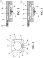
- Figs. 5 and 6 illustrate a pump mechanism 21A according to an implementation.
- the pump mechanism 21A can include a pump housing 63, a membrane 65, and an actuator 71.
- the pump mechanism 21A relies upon deformation of the membrane 65 to move between an original configuration in which the volume of a fluid chamber 67 defined between the membrane 65 and the pump housing 63 is zero or near-zero, and an expanded configuration in which the volume of the fluid chamber 67 is increased.
- the pump housing 63 is arranged to surround the outer radial edge of the membrane 65 and creates a seal with the membrane 65.
- the pump housing 63 can define at least one opening that extends into the pump housing 63 to form at least one internal passageway 69 to provide fluid communication between the fluid chamber 67 and a socket.
- the internal passageway 69 can be in fluid communication with the fluid chamber 67 and at least one valve 23 of the pump system 2.
- the at least one valve 23 can be attached directly to the pump housing 63 as seen in Figs. 5 and 6 . In other implementations, the at least one valve 23 can be separate from the pump housing 63.
- the actuator 71 can move the pump mechanism 21A between the original and expanded configurations. For instance, rotation of the actuator 71 in a first direction can move the pump mechanism 21A toward the expanded configuration and rotation of the actuator 71 in a second direction, opposite the first, can move the pump mechanism 21A toward the closed configuration.
- the actuator 71 can be driven by any suitable drive module.
- the pump mechanism 21 can be an electric vacuum generator, a membrane-type pump, a bladder-type pump, a peristaltic pump, a piston-type pump, or any other suitable pump mechanism.
- a control system 37 can be associated with the pump system 2.
- the control system 37 can be operable to control operation of one or more of the foregoing system components (e.g., pump mechanism 21, valve assembly 23, sensors 27, feedback system 31).
- the control system 37 can be internal to or external to the pump system 3.
- the control system 37 may be programmable for regulating pressure inside the socket 5 and/or monitoring activity of the user and/or vacuum suspension system 1.
- the control system 37 can include an input/output (I/O) module 39.
- the I/O module 39 can communicate with the pump system 2, the valve assembly 9, an end user, other modules of the control system 37, and/or other devices.
- a processing module 45 can execute computer executable instructions and/or process data.
- the processing module 45 may be operably coupled to a memory 47.
- the memory 47 can store an application including computer executable instructions, measurement data, and/or operational data constituting a program to perform certain acts (e.g., a part program, a software control program, etc.).
- the processing module 45 may be operably coupled to the memory 47 storing an application including computer executable instructions and data constituting a customized program to regulate vacuum in the socket 5.
- the memory 47 may be embodied as a computer readable medium, such as a random access memory ("RAM"), a hard disk drive, or a static storage medium such as a compact disk, DVD, or the like.
- the memory 47 may include the cloud or a network described below.
- the memory 47 may further store information and/or data obtained by the pump system 2.
- a sensing module 41 can direct one or more of the sensors 27 to detect pressure levels in the socket 5 and/or the vacuum suspension system 1. According to a variation, the sensing module 41 can direct one or more of the sensors 27 to detect movement/location of different components of the vacuum suspension system 1. In other implementations, the sensing module 41 can direct one or more of the sensors 27 to detect heartrate and/or blood pressure of the user.
- a regulating module 43 can direct the pump mechanism 21 to vary the vacuum in the socket 5 and/or vacuum suspension system 1.
- the regulating module 43 and/or the processing module 45 can obtain pressure information from the data collected by the sensors 27. Based on the pressure information, the regulating module 43 can direct the pump mechanism 21 to increase and/or decrease the vacuum in the socket 5. For instance, if the pressure information indicates that the vacuum in the socket 5 is too low, the regulating module 43 can direct the pump mechanism 21 to increase the vacuum. If the pressure information indicates the vacuum in the socket 5 is too high, the regulating module 43 can direct the valve assembly 9 to decrease the vacuum in the socket 5 by introducing air into the socket 5.
- obtaining the pressure information can include reading the data, analyzing the data, transforming the data, and/or processing the data.
- a feedback module 49 can direct the feedback system 31 to communicate information obtained by the pump system 2 to an end user (e.g., user or CPO) via the I/O module 39. For example, if the pressure information indicates that the vacuum in the socket 5 is too low, the feedback module 49 can direct the yellow LED 33B to illuminate and/or the vibrator 35 to vibrate, alerting the end user of a potential dangerous fit between the socket 5 and the residual limb.
- the control system 37 can include a monitoring module for obtaining the pressure information which can then be communicated to a user, CPO, and/or other intended party via the I/O module 39 for monitoring purposes.
- the regulating module 43 and/or the feedback module 49 may be omitted and the control system 37 may include the monitoring module.
- the monitoring module may be integrated with the regulating module.
- the control system 37 can be internal to or external to the pump system 3.
- the control system 37 can comprise or can be operably coupled to a system 61 having a computer device 51 as seen in Fig. 8 .
- the computer device 51 can display information to an end user and receive user input, respectively.
- the computer device 51 preferably is a mobile device.
- a mobile device is defined as a processing device routinely carried by a user. It typically has a display screen with touch input and/or a keyboard, and its own power source. As such, the computer device 51 can provide a user the freedom to use it almost anywhere.
- the computer device 51 can be a hand-held device.
- the computer device 51 can be a tablet computer, a smartphone, a laptop, a mobile telephone, a PDA, or other appropriate device. It will be appreciated that any of the methods and systems described herein may be adapted to couple the pump system 2 to a computer device 51 such as a desktop computer or the like in place of the mobile device.
- the computer device 51 is communicatively coupled to the pump system 3.
- the computer device 51 can be communicatively coupled to a server or computer system 53 over a network 55, such as for example, a Local Area Network ("LAN"), a Wide Area Network (“WAN”), and even the internet.
- the computer system 53 can be located remotely from the computer device 51.
- the computer system 53 can be used for controlling and/or monitoring the computer device 51 and/or the pump system 2.
- the computer system 53 can be used for exchanging information/files with the computer device 51 and/or pump system 2.
- the pump system 2 can send one or more files including pressure information and activity information to the computer device 51.
- the exact division of labor between the computer device 51, the pump system 2, and the computer system 53 may vary.
- the computer device 51 can perform nearly all operations and the pump system 2 merely carries out instructions that are received from the computer device 51.
- the computer device 51 receives and stores data/files from the pump system 2, and the pump system 2 performs all other operations. Any division of labor between the pump system 2, the computer device 51, and the computer system 53 is also within the scope of the present disclosure.
- a vacuum regulating routine or application of the pump system 2 will now be described.
- a vacuum regulating routine or application can be initiated in which the pump system 2 directs the sensors 27 to measure the vacuum in the socket 5 (shown in Fig. 1 ). This can include receiving user input specifying the initiation of the routine by the pump system 2 and/or other feedback or input.
- the sensing module 41 can output one or more sensing instructions via the I/O module 39 to the pressure sensor 29 without human intervention (e.g., without input from an operator). Automatically and without human intervention, the pressure sensor 29 can measure the pressure level within the socket 5 in accordance with the measurement instructions.
- the pressure data can be sent to one or more of the modules and/or stored in the memory 47 via the I/O module 39.
- the regulating module 43 can obtain pressure information from the pressure data. Obtaining the pressure information can include reading the data, analyzing the data, transforming the data, and/or processing the data. For example, the regulating module 43 and/or the processing module 45 can compare the pressure data to a value limit stored in the memory to obtain the pressure information.
- the regulating module 43 can output one or more pumping instructions via the I/O module 39 to the pump mechanism 21. If the pressure information indicates the pressure in the socket 5 is above the value limit, the pumping instructions can direct the pump mechanism 21 to increase the vacuum in the socket 5. If the pressure information indicates the pressure in the socket 5 is below the value limit, the pump instructions can direct the pump mechanism 21 and/or the valve assembly 9 (shown in Fig. 1 ) to decrease the vacuum in the socket 5. The pump mechanism and/or valve assembly 9 can then increase and/or decrease the pressure in the socket 5 based on the pumping instructions.
- the value limit can be a singular value, a set of values, or a range of values.
- the value limit can be a relative or absolute pressure level.
- the value limit can be a range of target pressure levels.
- the value limit can be selected based on user activity criteria and/or any other suitable criteria. In an implementation, the value limit can be set using an application on the computer device 51 or hand-held device.
- a feedback routine can include the feedback module 49 outputting one or more feedback instructions via the I/O module 39 to the feedback system 31 based upon the pressure information. For instance, if the pressure information indicates that the vacuum in the socket 5 is good, the feedback instructions can direct the green LED 33A to illuminate, confirming a secure and comfortable fit between the socket 5 and the residual limb. If the pressure information indicates that the vacuum is too high, the feedback instructions can direct the red LED 33C to illuminate, alerting the end user of a fit between the socket 5 and the residual that may be too tight. If the pressure information indicates that the vacuum is poor, the feedback instructions can direct the yellow LED 33B to illuminate, alerting the end user that the socket 5 may detach from the residual limb. The feedback instructions can also direct the vibrator 35 to vibrate if the pressure information indicates the vacuum is poor and/or too high, providing the user feedback regarding whether there is a proper fit between the residual limb and the socket 5.
- the feedback instructions can instruct the I/O module 39 to send the pressure information to the network 55 and/or computer system 53 through the computer device 51 for additional analysis and/or storage.
- an activity routine can be initiated in which the pump system 2 directs the sensors 27 to measure the activity of a user. This can include receiving user input specifying the initiation of the routine by the pump system 2 and/or feedback from one or more of the sensors 27.
- the sensing module 41 can output one or more sensing instructions via the I/O module 39 to the location sensor 17.
- the location sensor 17 can measure the activity of the user in accordance with the sensing instructions. For instance, the location sensor 17 can measure movement of the pump mechanism 21 based on the sensing instructions. The location sensor 17 can measure movement of the prosthetic foot 13 based on the sensing instructions. The location sensor 17 can measure the load and/or moment on the prosthetic foot 13 based on the sensing instructions. The location sensor 17 can measure movement of the residual limb relative to the socket 5 based on the sensing instructions. The location sensor 17 can measure stride, stride count, and/or stride count over time based on the sensing instructions. The location sensor 17 can measure speed and/or cadence of the user's gait based on the sensing instructions.
- the location sensor 17 can measure terrain based on the sensing instructions such as, for example, but not limited to, grade, ground hardness, and/or stairs climbing up and down.
- the location sensor 17 can measure stride time, stance time, swing time, active time on the prosthetic socket 5, and/or inactive time on the prosthetic socket 5 based on the sensing instructions.
- the location sensor 17 can measure tibia angle during stance and/or swing phase based on the sensing instructions.
- the location sensor 17 and/or another one of the sensors 27 can measure the user's heart rate, blood pressure, and/or breathing rate.
- the data collected by the location sensor 17 can be sent to one or more modules and/or stored in the memory 47 via the I/O module 39.
- the processing module 45 and/or the regulating module 43 can obtain activity information from the data collected by the location sensor 17, which, in turn, can be used to compile medical information about the user, information about the vacuum suspension system, the pump system, and/or the prosthetic foot.
- the activity information can be associated with one or more components of the system 1.
- the activity information can be used by the regulating module 43 and/or other modules to regulate the vacuum in the socket. For example, if the activity information indicates the user is in a period of activity or exercising (e.g., hiking, running, jogging, walking, jumping, climbing, or the like) the regulating module 43 can send pumping instructions to the pump mechanism 21 directing it to increase the vacuum in the socket 5. If the activity information indicates the user is in a period of inactivity, the regulating module 43 can send pumping instructions to the pump mechanism 21 directing it to decrease the vacuum in the socket 5.
- the activity information indicates the user is in a period of activity or exercising (e.g., hiking, running, jogging, walking, jumping, climbing, or the like) the regulating module 43 can send pumping instructions to the pump mechanism 21 directing it to increase the vacuum in the socket 5. If the activity information indicates the user is in a period of inactivity, the regulating module 43 can send pumping instructions to the pump mechanism 21 directing it to decrease the vacuum in the socket 5.
- the feedback module 49 can send feedback instructions to the feedback system 31 to warn the user of insufficient vacuum.
- the activity information to regulate the vacuum in the socket increases user comfort and safe use of the prosthesis.
- the activity information can provide information about the performance of the prosthetic foot during walking or stretching.
- the activity information can provide information about the user's health during specific activities or in general.
- the activity information can provide information to a third party medical professional that the user is having a heart attack or stroke.
- the activity information can also be used to evaluate performance of the pump mechanism 21.
- a vacuum performance routine or application implementation will now be described.
- the vacuum performance routine can be similar to the routines previously described except that it obtains vacuum performance information from the pressure and activity information.
- pressure information can be compared to activity information during a specific activity to evaluate the activity effectiveness of the pump system 2 and/or pump mechanism 21.
- change in pressure inside the socket 5 can be compared to tibia angle during stance and swing phases to determine the effectiveness of the pump mechanism during gait.
- change in pressure inside the socket 5 can be compared to relative movement between the residual limb and the socket 5 to determine the effectiveness of the pump mechanism when the residual limb changes volume and/or during use of the vacuum suspension system.
- change in pressure inside the socket 5 can be compared to movement between the prosthetic foot, pump mechanism, and/or other component and the socket.
- the effectiveness of the pump system 2 can advantageously be monitored and/or accessed. Further, the pump system 2 can be controlled based on different needs and/or activities of a user, providing versatility and useful information.
- Fig. 9 illustrates a method 100 in accordance with the present disclosure for regulating vacuum in a socket with a pump system includes a step 102 measuring pressure inside of a prosthetic socket using one or more sensors operatively coupled to a pump system to obtain pressure information associated with the inside of the socket.
- Step 102 can include the control system obtaining the pressure information from the data provided by the pressure sensor.
- Fig. 7 and the accompanying description depict and describe the regulating module 43 comparing data from the pressure sensor to a value limit to obtain pressure information and outputting pumping instructions to the pump mechanism based on the pressure information.
- Fig. 9 shows that the method 100 can include a step 104 of actuating the pump mechanism without human intervention to regulate vacuum inside the prosthetic socket based on the pressure information.
- Step 104 can include the control system outputting pumping instructions directing the pump mechanism to increase or decrease the vacuum in the socket based on the pressure information.
- Fig. 7 and the accompanying description depict and describe the regulating module transmitting pumping instructions to the pump mechanism and/or valve assembly to increase or decrease the vacuum in the socket based on the pressure information. The pump mechanism and/or the valve assembly can then vary the vacuum inside of the prosthetic socket based on the pumping instructions.
- Figs. 1-9 provide a number of components, schematics and mechanisms for regulating a vacuum in a prosthetic socket with a pump system based on feedback from one or more sensors. This has the effect of providing a more secure, safe, and comfortable fit between the socket and the residual limb. This also advantageously is faster, more accurate, and more consistent than conventional systems and methods.
- modules are defined here as an isolatable element that performs a defined function and has a defined interface to other elements.
- the modules described in this disclosure may be implemented in hardware, a combination of hardware and software, firmware, or a combination, all of which can be behaviorally equivalent. Modules may be implemented using computer hardware in combination with software routine(s) written in a computer language. It may be possible to implement modules using physical hardware that incorporates discrete or programmable analog and/or digital hardware. Examples of programmable hardware include computers, microcontrollers, microprocessors, application-specific integrated circuits, field programmable gate arrays, and complex programmable logic devices.
- the pressure regulating, activity monitoring, and/or vacuum performance routines or applications may be software embodied on a computer readable medium which when executed by a processor component of a computer device performs a sequence of steps.
- the application may be a mobile application or application software configured to run on smartphones, tablets computers, and/or other mobile devices.
- implementations of the present disclosure may comprise or utilize a special-purpose or general-purpose computer system that includes computer hardware, such as, for example, one or more processors and system memory, as discussed in greater detail below.
- Implementations of the present disclosure also include physical and other computer-readable media for carrying or storing computer-executable instructions and/or data structures.
- Such computer-readable media can be any available media that can be accessed by a general-purpose or special-purpose computer system.
- Computer-readable media that store computer-executable instructions and/or data structures are computer storage media.
- Computer-readable media that carry computer-executable instructions and/or data structures are transmission media.
- the present disclosure can comprise at least two distinctly different kinds of computer-readable media: computer storage media and transmission media.
- Computer storage media are physical storage media that store computer-executable instructions and/or data structures.
- Physical storage media include computer hardware, such as RAM, ROM, EEPROM, solid state drives (“SSDs”), flash memory, phase-change memory (“PCM”), optical disk storage, magnetic disk storage or other magnetic storage devices, or any other hardware storage device(s) which can be used to store program code in the form of computer-executable instructions or data structures, which can be accessed and executed by a general-purpose or special-purpose computer system to implement the disclosed functionality of the disclosure.
- Transmission media can include a network and/or data links which can be used to carry program code in the form of computer-executable instructions or data structures, and which can be accessed by a general-purpose or special-purpose computer system.
- a "network" is defined as one or more data links that enable the transport of electronic data between computer systems and/or modules and/or other electronic devices.
- program code in the form of computer-executable instructions or data structures can be transferred automatically from transmission media to computer storage media (or vice versa).
- program code in the form of computer-executable instructions or data structures received over a network or data link can be buffered in RAM within a network interface module (e.g., a "NIC"), and then eventually transferred to computer system RAM and/or to less volatile computer storage media at a computer system.
- a network interface module e.g., a "NIC”
- computer storage media can be included in computer system components that also (or even primarily) utilize transmission media.
- Computer-executable instructions comprise, for example, instructions and data which, when executed at one or more processors, cause a general-purpose computer system, special-purpose computer system, or special-purpose processing device to perform a certain function or group of functions.
- Computer-executable instructions may be, for example, binaries, intermediate format instructions such as assembly language, or even source code.
- a computer system may include a plurality of constituent computer systems.
- program modules may be located in both local and remote memory storage devices.
- Cloud computing environments may be distributed, although this is not required. When distributed, cloud computing environments may be distributed internationally within an organization and/or have components possessed across multiple organizations.
- “cloud computing” is defined as a model for enabling on-demand network access to a shared pool of configurable computing resources (e.g., networks, servers, storage, applications, and services). The definition of “cloud computing” is not limited to any of the other numerous advantages that can be obtained from such a model when properly deployed.
- a cloud computing model can be composed of various characteristics, such as on-demand self-service, broad network access, resource pooling, rapid elasticity, measured service, and so forth.
- a cloud computing model may also come in the form of various service models such as, for example, Software as a Service (“SaaS”), Platform as a Service (“PaaS”), and Infrastructure as a Service (“IaaS”).
- SaaS Software as a Service
- PaaS Platform as a Service
- IaaS Infrastructure as a Service
- the cloud computing model may also be deployed using different deployment models such as private cloud, community cloud, public cloud, hybrid cloud, and so forth.
- Some implementations may comprise a system that includes one or more hosts that are each capable of running one or more virtual machines.
- virtual machines emulate an operational computing system, supporting an operating system and perhaps one or more other applications as well.
- each host includes a hypervisor that emulates virtual resources for the virtual machines using physical resources that are abstracted from view of the virtual machines.
- the hypervisor also provides proper isolation between the virtual machines.
- the hypervisor provides the illusion that the virtual machine is interfacing with a physical resource, even though the virtual machine only interfaces with the appearance (e.g., a virtual resource) of a physical resource. Examples of physical resources including processing capacity, memory, disk space, network bandwidth, media drives, and so forth.
Landscapes
- Health & Medical Sciences (AREA)
- Engineering & Computer Science (AREA)
- Transplantation (AREA)
- Vascular Medicine (AREA)
- Animal Behavior & Ethology (AREA)
- Cardiology (AREA)
- Biomedical Technology (AREA)
- Heart & Thoracic Surgery (AREA)
- Veterinary Medicine (AREA)
- Life Sciences & Earth Sciences (AREA)
- Oral & Maxillofacial Surgery (AREA)
- General Health & Medical Sciences (AREA)
- Public Health (AREA)
- Orthopedic Medicine & Surgery (AREA)
- Mechanical Engineering (AREA)
- General Engineering & Computer Science (AREA)
- Prostheses (AREA)
Claims (14)
- Système de suspension à dépression (1), comprenant :une emboîture prothétique (5) apte à recevoir un membre résiduel ;un système à pompe (2) incluant un mécanisme à pompe (21) présentant une communication de fluide avec l'emboîture prothétique (5) ;une pluralité de capteurs (16, 27) associée à au moins un élément parmi l'emboîture prothétique (5) et le mécanisme à pompe (21) ;un système de commande (37) raccordé d'une manière permettant le fonctionnement au mécanisme à pompe (21) et à la pluralité de capteurs (16, 27), le système de commande (37) étant agencé pour recevoir et traiter des données provenant de la pluralité de capteurs (16, 27) et pour actionner le mécanisme à pompe (21) sur la base des données reçues de la pluralité de capteurs (16 ; 27) ; un module de régulation (43) agencé pour recevoir des informations de la pluralité de capteurs (16 ; 27), etau moins un ensemble de valve (23) présentant une communication de fluide avec le système à pompe (2), le au moins un ensemble de valve (23) pouvant être commandé par le système de commande (37) et réglé en fonction de la direction à partir du module de régulation (43) ;caractérisé en ce quela pluralité de capteurs (16, 27) est agencée pour mesurer au moins une fluctuation de volume du membre résiduel, des modifications de pression dans l'emboîture prothétique, et un déplacement relatif entre le membre résiduel et l'emboîture prothétique ;les données provenant de la pluralité de capteurs sont représentatives des modifications de pression dans l'emboîture prothétique, du déplacement relatif entre le membre résiduel et l'emboîture prothétique, et de la fluctuation de volume du membre résiduel sur une période temps, etle système de commande (37) est agencé pour générer des informations de performance de dépression représentatives d'une efficacité du mécanisme à pompe en comparant la modification de pression dans l'emboîture prothétique et le déplacement relatif entre le membre résiduel et l'emboîture prothétique lorsque le volume du membre résiduel fluctue.
- Système selon la revendication 1, dans lequel le système de commande (37) est agencé pour diriger le mécanisme à pompe (21) afin d'augmenter une dépression dans l'emboîture prothétique (5) si les données reçues indiquent qu'une pression dans l'emboîture prothétique (5) est supérieure à une valeur limite.
- Système selon l'une quelconque des revendications précédentes, dans lequel le système de commande (37) est agencé pour diriger le mécanisme à pompe (21) afin de diminuer une dépression dans l'emboîture prothétique (5) si les données reçues indiquent qu'une pression dans l'emboîture prothétique (5) est inférieure à une valeur limite.
- Système selon l'une quelconque des revendications précédentes, dans lequel les données incluent des informations d'activité associées à un niveau d'activité d'un utilisateur.
- Système selon la revendication 4, dans lequel le système de commande (37) est agencé pour diriger le mécanisme à pompe (21) afin d'augmenter une dépression dans l'emboîture prothétique (5) si les informations d'activité indiquent qu'un utilisateur est dans une période d'activité, et/ou dans lequel le système de commande (37) est agencé pour diriger le mécanisme à pompe (21) afin de diminuer une dépression dans l'emboîture prothétique (5) si les informations d'activité indiquent qu'un utilisateur est dans une période d'inactivité.
- Système selon la revendication 4 ou 5, dans lequel les informations d'activité incluent au moins un élément parmi des informations de fréquence cardiaque ou des informations de pression artérielle.
- Système selon la revendication 4 ou 5, dans lequel les informations d'activité incluent des informations de force.
- Système selon l'une quelconque des revendications précédentes, dans lequel la pluralité de capteurs est apte à détecter au moins un emplacement et un mouvement du membre résiduel par rapport à l'emboîture prothétique.
- Système selon l'une quelconque des revendications précédentes, dans lequel la pluralité de capteurs (16, 27) est apte à détecter au moins un élément parmi un emplacement ou un mouvement du mécanisme à pompe (21).
- Système selon l'une quelconque des revendications précédentes, dans lequel la pluralité de capteurs (16, 27) est apte à détecter au moins un élément parmi un emplacement ou un déplacement d'un pied prothétique (13) raccordé d'une manière permettant le fonctionnement à l'emboîture prothétique (5).
- Système selon la revendication 10, dans lequel le système à pompe (2) est fixé sur le pied prothétique (13).
- Système selon la revendication 10, dans lequel le système à pompe (2) est fixé sur un système d'adaptateur (15) s'étendant entre l'emboîture prothétique (5) et le pied prothétique (13).
- Système selon l'une quelconque des revendications précédentes, dans lequel le système à pompe (2) est fixé sur l'emboîture prothétique (5).
- Système selon l'une quelconque des revendications précédentes, dans lequel le système à pompe inclut un système à rétroaction (31), lequel est en communication avec le système de commande (37) et agencé pour communiquer des informations obtenues par le système à pompe (2) à un utilisateur final par un son audible ou un éclairage.
Applications Claiming Priority (2)
| Application Number | Priority Date | Filing Date | Title |
|---|---|---|---|
| US201562168088P | 2015-05-29 | 2015-05-29 | |
| PCT/US2016/033915 WO2016196081A1 (fr) | 2015-05-29 | 2016-05-24 | Système de pompe destiné à être utilisé avec un dispositif prothétique |
Publications (2)
| Publication Number | Publication Date |
|---|---|
| EP3302371A1 EP3302371A1 (fr) | 2018-04-11 |
| EP3302371B1 true EP3302371B1 (fr) | 2024-10-16 |
Family
ID=56098427
Family Applications (1)
| Application Number | Title | Priority Date | Filing Date |
|---|---|---|---|
| EP16727097.4A Active EP3302371B1 (fr) | 2015-05-29 | 2016-05-24 | Système de pompe destiné à être utilisé avec un dispositif prothétique |
Country Status (3)
| Country | Link |
|---|---|
| US (2) | US10179055B2 (fr) |
| EP (1) | EP3302371B1 (fr) |
| WO (1) | WO2016196081A1 (fr) |
Families Citing this family (17)
| Publication number | Priority date | Publication date | Assignee | Title |
|---|---|---|---|---|
| US10842653B2 (en) | 2007-09-19 | 2020-11-24 | Ability Dynamics, Llc | Vacuum system for a prosthetic foot |
| US9198780B2 (en) | 2012-02-14 | 2015-12-01 | Ossur Hf | Vacuum assisted suspension system |
| WO2013165909A1 (fr) | 2012-04-30 | 2013-11-07 | Ossur Hf | Dispositif prothétique, système et procédé pour accroître une attache de mise au vide |
| US9757256B2 (en) | 2014-07-01 | 2017-09-12 | Ossur Hf | Pump mechanism for vacuum suspension system |
| WO2016112030A1 (fr) | 2015-01-08 | 2016-07-14 | Ossur Iceland Ehf | Mécanisme de pompe |
| EP3297582B1 (fr) | 2015-05-21 | 2019-04-17 | Ossur Iceland EHF | Système de pompe |
| WO2017035294A1 (fr) | 2015-08-25 | 2017-03-02 | Ossur Iceland Ehf | Système prothétique |
| WO2017034841A1 (fr) | 2015-08-27 | 2017-03-02 | Ossur Iceland Ehf | Système de pompe |
| US10512554B2 (en) | 2016-08-26 | 2019-12-24 | Ossur Iceland Ehf | Pump system |
| EP3547984B1 (fr) | 2016-12-01 | 2022-05-18 | Össur Iceland EHF | Béquille avec stockage d'énergie et retour d'énergie |
| USD851388S1 (en) * | 2017-05-31 | 2019-06-18 | Össur Iceland Ehf | Crutch |
| WO2019079143A1 (fr) | 2017-10-20 | 2019-04-25 | Ossur Iceland Ehf | Système de gestion de chaleur et de transpiration |
| US11298249B2 (en) | 2018-06-07 | 2022-04-12 | Ossur Iceland Ehf | Prosthetic interface |
| US11253378B2 (en) | 2019-05-24 | 2022-02-22 | Tim Lee Stevenson | Hands-free apparatus to apply a liner to an amputated appendage |
| US11648016B2 (en) | 2019-12-28 | 2023-05-16 | Depuy Ireland Unlimited Company | Cannulated, modular femoral broach and surgical instrument handle |
| US12578261B2 (en) | 2023-06-05 | 2026-03-17 | The United States Of America As Represented By The Government Publishing Office | ID card peel sample preparation apparatus and method |
| EP4739256A2 (fr) * | 2023-07-05 | 2026-05-13 | L&W Latency, Inc. | Système médical gonflable |
Citations (5)
| Publication number | Priority date | Publication date | Assignee | Title |
|---|---|---|---|---|
| US20040030411A1 (en) * | 1999-06-03 | 2004-02-12 | Caspers Carl A. | Pulsating pressure chamber and method for fluid management |
| WO2009149412A1 (fr) * | 2008-06-06 | 2009-12-10 | Hanger Orthopedic Group, Inc. | Dispositif prothétique et système de raccordement employant du vide |
| US20110060421A1 (en) * | 2006-09-12 | 2011-03-10 | James Jay Martin | Control system for prosthesis |
| US20110270413A1 (en) * | 2005-06-10 | 2011-11-03 | The Ohio Willow Wood Company | Prosthetic system and method utilizing microprocessor-controlled electric vacuum pump |
| US20130289741A1 (en) * | 2012-04-30 | 2013-10-31 | Ossur Hf | Prosthetic device, system and method for increasing vacuum attachment |
Family Cites Families (245)
| Publication number | Priority date | Publication date | Assignee | Title |
|---|---|---|---|---|
| DE145981C (fr) | ||||
| US708685A (en) | 1902-01-28 | 1902-09-09 | Charles P White | Artificial limb. |
| US980457A (en) | 1910-01-13 | 1911-01-03 | Justin Kay Toles | Artificial limb. |
| US1288803A (en) | 1918-07-01 | 1918-12-24 | Friedrich Conrad Beck | Apparatus for fastening artificial legs on the body. |
| GB136504A (en) | 1919-08-11 | 1919-12-18 | Emmett Blevens | Combined Stocking and Pad for Amputated Legs. |
| GB267988A (en) | 1925-09-18 | 1927-03-18 | Charles Albert Blatchford | Improvements in or connected with artificial limbs |
| US1586015A (en) | 1926-01-14 | 1926-05-25 | Underwood Ernest Walter | Artificial limb |
| DE685861C (de) | 1938-04-29 | 1939-12-27 | Alois Geisen | Kuenstliches Bein |
| US2424278A (en) | 1945-10-08 | 1947-07-22 | Paul W Kunkel | Method of forming sockets for artificial limbs |
| US2464443A (en) | 1947-11-17 | 1949-03-15 | Charles V Ganoe | Prosthetic limb socket for amputees |
| US2530285A (en) | 1947-12-11 | 1950-11-14 | John G Catranis | Artificial leg |
| US2533404A (en) | 1948-08-13 | 1950-12-12 | Sharp Oscar | Artificial limb and valve therefor |
| US2606325A (en) | 1949-08-01 | 1952-08-12 | Carl A Nielson | Age and stain-resisting article of plasticized polyvinyl chloride |
| US2696011A (en) | 1951-06-01 | 1954-12-07 | John J Galdik | Artificial leg with suction socket |
| US2671225A (en) | 1951-11-05 | 1954-03-09 | Bardach Schoene Company Inc | Artificial limb stump socket |
| US2696010A (en) | 1952-06-30 | 1954-12-07 | George B Robinson | Pneumatically operated artificial hand |
| US2664572A (en) | 1952-10-27 | 1954-01-05 | Blevens Emmett | Artificial limb |
| BE551068A (fr) | 1955-09-16 | |||
| US2790180A (en) | 1955-11-07 | 1957-04-30 | Adolph F Hauser | Artificial limb and valve therefor |
| US2808593A (en) | 1956-02-07 | 1957-10-08 | Andersen Algot | Artificial limbs |
| US3253600A (en) | 1963-09-06 | 1966-05-31 | William M Scholl | Orthopedic inlay for footwear |
| US3322873A (en) | 1963-09-30 | 1967-05-30 | Dow Corning | Method of making a resilient custom-fit body protector |
| US3316900A (en) | 1964-08-18 | 1967-05-02 | Lillian M Young | Leg brace hinge guard |
| US3377416A (en) | 1965-01-22 | 1968-04-09 | Edward J. Kandel | Method of making liner for artificial limb |
| FR1429464A (fr) | 1965-02-01 | 1966-02-25 | Gaine de protection notamment pour le port d'appareil prothétique et appareil de prothèse | |
| FR1532625A (fr) | 1967-06-02 | 1968-07-12 | Perfectionnement aux prothèses des membres | |
| US3557387A (en) | 1968-11-12 | 1971-01-26 | Liberty Mutual Insurance Corp | Externally powered joint prosthesis |
| US3631542A (en) | 1969-08-11 | 1972-01-04 | Univ Iowa State Res Found | Myoelectric brace |
| US3858379A (en) | 1970-06-09 | 1975-01-07 | Us Army | Process for making a polyvinyl alcohol gel support pad |
| US3712298A (en) | 1970-08-25 | 1973-01-23 | Nat Res Dev | Medical treatment apparatus |
| US3732578A (en) | 1971-03-01 | 1973-05-15 | H Pollack | Diagnostic and interfacial pad for use with the socket of a prosthetic device |
| US4282325A (en) | 1971-05-14 | 1981-08-04 | Syva Company | Enzyme bound corticosteroids |
| US3751733A (en) | 1972-02-22 | 1973-08-14 | J Fletcher | Tactile sensing means for prosthetic limbs |
| US3947156A (en) * | 1972-03-08 | 1976-03-30 | Erich Becker | Diaphragm pump, particularly for the generation of vacuum |
| US3991424A (en) | 1972-03-20 | 1976-11-16 | Ipos Gesellschaft Fur Integrierte Prothesenentwicklung Und Orthopadietechnischen Service M.B.H. & Co. K.G. | Compression sheath for below knee amputated limbs |
| US3975350A (en) | 1972-08-02 | 1976-08-17 | Princeton Polymer Laboratories, Incorporated | Hydrophilic or hydrogel carrier systems such as coatings, body implants and other articles |
| US3806958A (en) | 1972-08-18 | 1974-04-30 | L Gusev | Thigh prosthesis |
| US4106745A (en) | 1973-05-07 | 1978-08-15 | Phillips Petroleum Company | Apparatus for attaching an insert in a mold |
| US3889301A (en) | 1974-05-06 | 1975-06-17 | Bonner Marion K | Therapeutic stump treating air sac prosthesis |
| US3922727A (en) | 1974-07-17 | 1975-12-02 | Frank Bianco | Apparatus to assist fastening of an artificial limb |
| US3895405A (en) | 1974-09-12 | 1975-07-22 | Clyde A Edwards | Adjustable insole and method |
| US4010052A (en) | 1974-09-24 | 1977-03-01 | Bandag Incorporated | Molding valve stems to rubber article |
| US4133776A (en) | 1976-03-15 | 1979-01-09 | Union Carbide Corporation | Manufacture of polyfunctional compounds |
| FR2345139A1 (fr) | 1976-03-22 | 1977-10-21 | Belzidsky David | Combine de protection pour membre ampute |
| DE2729800A1 (de) | 1977-07-01 | 1979-01-04 | Walter Dr Med Surerus | Doppelventil zum einbau in prothesensaugschaefte mit ringfoermiger stuetzeinlage |
| DE2811381A1 (de) | 1978-03-16 | 1979-09-27 | Daimler Benz Ag | Regler fuer eine einspritzpumpe einer luftverdichtenden brennkraftmaschine |
| SE423485B (sv) | 1978-07-27 | 1982-05-10 | Torsten Lars Evert Pettersson | Sett och anordning for tillverkning av underbensproteser |
| US4283800A (en) | 1979-03-19 | 1981-08-18 | Wilson Michael T | Adjustable prosthetic element |
| AT364073B (de) | 1979-05-17 | 1981-09-25 | Grossberger Gerhard | Unterschenkelprothese |
| SE420048B (sv) | 1980-01-28 | 1981-09-14 | Ossur Kristinsson | Anordning for anbringning av en ben- eller armprotes pa en amputationsstump |
| GB2069847B (en) | 1980-02-22 | 1985-01-23 | Blatchford & Sons Ltd | Artificial limb |
| US4466936A (en) | 1981-02-03 | 1984-08-21 | Bayer Aktiengesellschaft | Production of molds using gel compositions with depot action based on a polyurethane matrix and relatively high molecular weight polyols |
| DE3103564A1 (de) | 1981-02-03 | 1982-08-26 | Bayer Ag, 5090 Leverkusen | Gel-polster, verfahren zu deren herstellung und deren verwendung |
| AU558611B2 (en) | 1981-02-03 | 1987-02-05 | Bayer Aktiengesellschaft | Polyurethane gel |
| FR2501999A1 (fr) | 1981-03-20 | 1982-09-24 | Godo Jean Claude | Prothese de membre inferieur telescopique 3 axes |
| US4381768A (en) | 1981-05-18 | 1983-05-03 | Stainless Mfg., Inc. | Knee orthosis |
| FR2521001A1 (fr) | 1982-02-05 | 1983-08-12 | Belzidsky David | Dispositif fixe prothese |
| GB2149309B (en) | 1982-03-02 | 1985-11-20 | Blatchford & Sons Ltd | Making artificial limbs |
| DE3221920A1 (de) | 1982-06-11 | 1983-04-07 | Surerus, Walter, Dr., 7016 Gerlingen | Schaft einer prothese |
| SE445968B (sv) | 1982-09-10 | 1986-08-04 | Kjell Goran Engstrom | Ventil for sugprotes |
| US4704129A (en) | 1984-07-10 | 1987-11-03 | Massey Peyton L | Reshapable prosthesis |
| US4623354A (en) | 1984-10-22 | 1986-11-18 | Northwestern University | Myoelectrically controlled artificial hand |
| US4635626A (en) | 1984-11-16 | 1987-01-13 | Max Lerman | Prosthetic stockings |
| GB2181691B (en) | 1985-10-21 | 1990-05-23 | Porvair Ltd | Gloves |
| US4655779A (en) | 1985-10-31 | 1987-04-07 | Janowiak Christopher S | Air system prosthesis for amputees |
| US4828325A (en) | 1986-05-16 | 1989-05-09 | University Of Tennessee Research Corporation | Method of making a custom fitted composite foamed cushion, a preform kit and the resultant product of the process |
| GB8622454D0 (en) | 1986-09-18 | 1986-10-22 | Causton B E | Limb prosthesis production |
| US4822371A (en) | 1987-01-23 | 1989-04-18 | Jolly David F | Reinforced elastic sleeve for use with a limb prosthetic device |
| US5846063A (en) | 1987-05-26 | 1998-12-08 | Nikola Lakic | Miniature universal pump and valve for inflatable liners |
| SE8801686L (en) | 1987-09-22 | 1989-03-23 | Inge Sandmark | Device for fitting or removing artificial limbs - produces vacuum or excess pressure transmitted to cavity in extremity of user |
| GB2213380A (en) | 1987-12-11 | 1989-08-16 | Gore & Ass | Protective cover for amputated limb stump |
| US5007937A (en) | 1988-03-31 | 1991-04-16 | New York University Medical Center | Structure for enhanced retention of artificial limbs and method of fabrication |
| US6066107A (en) | 1988-08-05 | 2000-05-23 | Habermeyer; Peter | Apparatus for the surroundive fixation of extremities |
| US4908037A (en) | 1988-09-16 | 1990-03-13 | Ross Michael R | Suspension prosthetic sleeve for rigorous activity |
| FI79021C (fi) | 1988-09-28 | 1989-11-10 | Martti J O Filppula | PROTES. SIIRRETTY PAEIVAEMAEAERAE-FOERSKJUTET DATUM PL 14 ç 10.10.88 |
| US5108455A (en) | 1988-10-21 | 1992-04-28 | Telikicherla Madan M | Lower limb prosthesis having removable rigid amputation stump dressing |
| US4999932A (en) | 1989-02-14 | 1991-03-19 | Royce Medical Company | Variable support shoe |
| US4923475A (en) | 1989-02-21 | 1990-05-08 | Gosthnian Barry M | Inflatable limb prosthesis with preformed inner surface |
| SU1667855A1 (ru) | 1989-07-12 | 1991-08-07 | Ленинградский научно-исследовательский институт протезирования | Протез нижней конечности |
| US5258037A (en) | 1990-07-13 | 1993-11-02 | Caspers Carl A | Prosthetic liner and method of making the liner with a prosthesis socket |
| US5571208A (en) | 1990-07-13 | 1996-11-05 | Caspers; Carl A. | Reinforced prosthetic polyurethane hypobaric sleeve |
| US5534034A (en) | 1990-07-13 | 1996-07-09 | Caspers; Carl A. | Prosthetic polyurethane liner and sleeve for amputees |
| SU1821177A1 (en) | 1990-10-08 | 1993-06-15 | Le Nii Protezirovaniya | Femur prosthesis with active stroke function |
| SU1771722A1 (ru) | 1990-10-17 | 1992-10-30 | Le Nii Protezirovaniya | Пpиemhaя гильзa пpoteзa bepxheй koheчhoctи |
| SU1812982A3 (en) | 1990-11-20 | 1993-04-30 | Volgogradsky Politekh Inst | Fastening of prosthesis |
| US5376129A (en) | 1990-12-04 | 1994-12-27 | Board Of Regents, The University Of Texas System | Method and apparatus for making prosthetic socket preforms, prosthetic sockets, and socket attachment component |
| US5108456A (en) | 1991-01-28 | 1992-04-28 | Coonan Iii Thomas J | Prosthetic appliance |
| DE4114213A1 (de) | 1991-05-01 | 1992-11-05 | Bayer Ag | Gelmassen, sowie deren herstellung und verwendung |
| ES1017741Y (es) | 1991-05-31 | 1992-08-01 | Velez Segura Juan | Acoplamiento para protesis de extremidades. |
| US5139523A (en) | 1991-07-12 | 1992-08-18 | Paton Matthew T | Artificial limb socket apparatus |
| US5163965A (en) | 1991-07-29 | 1992-11-17 | Becker Orthopedic Appliance Company | Prosthetic attachment device and method |
| US5201774A (en) | 1991-08-23 | 1993-04-13 | United States Manufacturing Company | Prosthetic valve system and process for sealing a socket |
| WO1993005958A1 (fr) | 1991-09-25 | 1993-04-01 | W.L. Gore & Associates, Inc. | Materiau de protection corporelle en caoutchouc cellulaire impermeable a l'air et a structure stratifiee |
| US5133776A (en) | 1991-12-11 | 1992-07-28 | Crowder Dan M | Prosthetic volume compensation device |
| US5314497A (en) | 1991-12-23 | 1994-05-24 | Fay John N | Apparatus and method for sealing a liner to a prosthesis |
| JP2849882B2 (ja) | 1992-02-24 | 1999-01-27 | 株式会社ナブコ | 義足用シリンダ |
| US5211667A (en) | 1992-04-22 | 1993-05-18 | Danforth Michael B | Guard for residuum after amputation |
| US5221222A (en) | 1992-07-20 | 1993-06-22 | Chris A. Becker | Novelty sleeve depicting a muscular arm |
| CA2098945C (fr) | 1992-10-13 | 1997-07-15 | Carl A. Caspers | Manchon pour membre artificiel et methode de fabrication dudit manchon adapte a la cavite de la prothese |
| US5490537A (en) | 1993-04-01 | 1996-02-13 | Hill; David A. | Prosthesis air valve assembly and tool therefor |
| DE9309472U1 (de) | 1993-06-25 | 1993-08-26 | BRADO Trikotagen GmbH vormals Bräunsdorfer Strumpffabrik, 09112 Chemnitz | Gestrickter Stumpfstrumpf |
| US5376131A (en) | 1993-07-01 | 1994-12-27 | Manhasset Orthotics And Prosthetics, Ltd. | Suction socket for artificial limb |
| US5480455A (en) | 1993-08-25 | 1996-01-02 | W. L. Gore & Associates, Inc. | Lining material for use with prosthetics and similar devices and method for making and using same |
| JPH0822295B2 (ja) | 1993-12-03 | 1996-03-06 | 株式会社奈良義肢 | 義足または義手の装着構造 |
| FR2714201B1 (fr) | 1993-12-22 | 1996-03-01 | Sgs Thomson Microelectronics | Circuit décodeur de ligne pour mémoire fonctionnant sous de faibles tensions d'alimentation. |
| DE4402655C1 (de) | 1994-01-29 | 1995-04-20 | Sartorius Gmbh | Elektrische Waage mit Korrektur des Feuchteeinflusses |
| US5507834A (en) | 1994-05-17 | 1996-04-16 | Laghi; Aldo A. | Transparent silicone suction socket |
| US6206934B1 (en) | 1998-04-10 | 2001-03-27 | Flex-Foot, Inc. | Ankle block with spring inserts |
| DE9417913U1 (de) | 1994-11-09 | 1995-03-09 | Voß, Jürgen, 09212 Bräunsdorf | Gestrickter Wollstumpfstrumpf mit maschenfester Öffnung in der Stumpfstrumpf-Spitze |
| DE9419211U1 (de) | 1994-11-30 | 1995-02-02 | Carstens, Felix, 67433 Neustadt | Künstliches Glied |
| EP0797413B1 (fr) | 1994-12-09 | 2003-11-05 | F. Barry Bays | Ensemble de valve d'abaissement de la pression du liquide synovial |
| US5728167A (en) | 1995-01-11 | 1998-03-17 | Lohmann; Klaus H. | Prosthetic sock for reducing movement between residual limb and prosthesis |
| US5593454A (en) | 1995-01-12 | 1997-01-14 | Helmy; Nashat N. | Artificial limb mounting apparatus |
| US5732578A (en) | 1995-02-24 | 1998-03-31 | Hyundai Metal Co., Ltd. | Device for maintaining the horizontality of a door lock lever |
| US5830237A (en) | 1996-03-05 | 1998-11-03 | Ohio Willow Wood Company | Gel and cushioning devices |
| FR2735018B1 (fr) | 1995-06-09 | 1997-07-11 | Proteval | Piece prothetique pneumatique pour l'articulation du genou |
| US5662715A (en) | 1995-07-19 | 1997-09-02 | Materials Engineering And Development, Inc. | Modular interface connector for a prosthetic limb |
| US5735906A (en) | 1995-07-26 | 1998-04-07 | Caspers; Carl A. | Hypobarically-controlled artificial limb with detents for amputees |
| US5549709A (en) | 1995-07-26 | 1996-08-27 | Caspers; Carl A. | Hypobarically-Controlled artificial limb for amputees |
| US6287345B1 (en) | 1995-08-18 | 2001-09-11 | The Ohio Willow Wood Company | Valve assembly for a prosthetic limb |
| US5702489A (en) | 1995-08-18 | 1997-12-30 | Materials Engineering And Development, Inc. | Valve assembly for a prosthetic limb |
| ES2152353T3 (es) | 1995-09-08 | 2001-02-01 | Bock Orthopaed Ind | Protesis de pierna. |
| US5702488A (en) | 1995-09-12 | 1997-12-30 | Model & Instrument Development Corporation | Prosthetic pylon having an enclosed compressible volume of fluid to support a patient's weight |
| US5658353A (en) | 1995-10-31 | 1997-08-19 | Layton; Harry W. | Method for donning or doffing an artificial limb |
| US5888216A (en) | 1996-03-18 | 1999-03-30 | Haberman; Louis J. | Prosthesis liner for below-knee amputees |
| GB2311466B (en) | 1996-03-29 | 1999-11-10 | Steeper Hugh Ltd | A prosthetic foot |
| CA2260801A1 (fr) | 1996-07-31 | 1998-02-05 | Ohio Willow Wood Company | Gel et dispositifs d'amortissement |
| US6964688B1 (en) | 1996-07-31 | 2005-11-15 | Ohio Willow Wood Company | Tube sock-shaped covering |
| US5728168A (en) | 1996-10-29 | 1998-03-17 | Alps South Corporation | Elastomer reinforcement of an elastomer interface membr for residual limb of an amputee |
| US5961556A (en) | 1996-12-31 | 1999-10-05 | Lord Corporation | Prosthetic suspension unit having elastomeric energy storage units |
| US6063125A (en) | 1997-02-14 | 2000-05-16 | Ohio Willow Wood Company | Suspension/alignment for prosthetic limbs |
| US5888230A (en) | 1997-04-01 | 1999-03-30 | Helmy; Nashat N. | Modular liner for limb stump prosthesis |
| DE29823435U1 (de) | 1997-04-24 | 1999-07-29 | Otto Bock Orthopädische Industrie Besitz- und Verwaltungs-Kommanditgesellschaft, 37115 Duderstadt | Fußeinsatz für einen Kunstfuß |
| US5980577A (en) | 1997-05-01 | 1999-11-09 | Radis; Vasilis | Protective item supporting an appendage |
| WO1999005991A2 (fr) | 1997-08-01 | 1999-02-11 | Alt Artificial Limb Technology Ltd. | Accumulateur d'energie induite par la marche |
| US5944760A (en) | 1997-08-04 | 1999-08-31 | Roland J. Christensen Family Limited Partnership | Prosthetic foot with reinforcing member |
| US5984972A (en) | 1997-09-18 | 1999-11-16 | Amputee Solutions, Inc. | Pylon assembly for leg prosthesis |
| US5888231A (en) | 1997-10-08 | 1999-03-30 | Minnesota Mining And Manufacturing Company | Custom-molded liner for artificial limb socket |
| WO1999052475A1 (fr) | 1998-04-10 | 1999-10-21 | Phillips L Van | Prothese comportant un module amortisseur avec ressort a boudin |
| JP4212174B2 (ja) | 1998-04-11 | 2009-01-21 | オットー・ボック・ヘルスケア・ゲーエムベーハー | 人工足用の足部ブシュ |
| US6334876B1 (en) | 1998-05-05 | 2002-01-01 | Dale Perkins | Safety suction valve |
| US6362387B1 (en) | 1998-06-15 | 2002-03-26 | Tamarack Habilitation Technologies, Inc. | Self-adhering friction reducing liner and method of use |
| US6149691A (en) | 1998-06-26 | 2000-11-21 | Fay; John N. | Self-inflating socket having encased gel |
| WO2000003665A1 (fr) | 1998-07-15 | 2000-01-27 | Caspers Carl A | Coiffe prothetique distale, garniture et fourreau |
| US6117117A (en) | 1998-08-24 | 2000-09-12 | Advanced Cardiovascular Systems, Inc. | Bifurcated catheter assembly |
| US6110138A (en) | 1999-02-01 | 2000-08-29 | Tagg Industries, L.L.C. | Stance-correcting knee brace |
| US6361568B1 (en) | 1999-02-09 | 2002-03-26 | Alps South Corporation | Prosthetic sleeve with air outlet valve |
| DE29905020U1 (de) | 1999-03-19 | 1999-07-15 | medi Bayreuth Weihermüller und Voigtmann GmbH & Co. KG, 95448 Bayreuth | Kompensationssystem für Prothesen |
| US6602295B1 (en) | 1999-05-24 | 2003-08-05 | Ohio Willow Wood Company | Prosthetic foot having shock absorption |
| US6726726B2 (en) | 1999-06-03 | 2004-04-27 | Otto Bock Healthcare Lp | Vacuum apparatus and method for managing residual limb volume in an artificial limb |
| US6554868B1 (en) | 1999-06-03 | 2003-04-29 | Carl A. Caspers | Vacuum pump and shock absorber for artificial limb |
| US6508842B1 (en) | 1999-06-03 | 2003-01-21 | Barbara J. Caspers | Socket liner for artificial limb |
| US20010016781A1 (en) | 1999-06-03 | 2001-08-23 | Caspers Carl A. | Osmotic membrane and vacuum system for artificial limb |
| US20040098136A1 (en) | 1999-06-03 | 2004-05-20 | Caspers Carl A. | Socket liner for artificial limb with permanent attachment to socket |
| WO2000074611A2 (fr) | 1999-06-03 | 2000-12-14 | Caspers-Schneider Technologies,Inc. | Emboiture commandee par voie hypobare pour membre artificiel |
| US6926742B2 (en) | 1999-06-03 | 2005-08-09 | Otto Bock Healthcare Lp | Plate/socket attachment for artificial limb vacuum pump |
| US6645253B2 (en) | 1999-06-03 | 2003-11-11 | Carl A. Caspers | Vacuum pump and shock absorber for artificial limb |
| US6231617B1 (en) | 1999-07-14 | 2001-05-15 | John N. Fay | Prosthetic liner having longitudinal inelasticity |
| US6273918B1 (en) | 1999-08-26 | 2001-08-14 | Jason R. Yuhasz | Magnetic detachment system for prosthetics |
| USD429335S (en) | 1999-09-03 | 2000-08-08 | Caspers-Schneider Technologies, Inc. | Prosthetic liner reinforcement patch |
| KR20030011075A (ko) | 2000-03-14 | 2003-02-06 | 오서 에이치에프 | 보철 응용에 유용한 복합 탄성 재료 및 그것으로 제조된흡인 라이너 |
| US6485776B2 (en) | 2000-03-15 | 2002-11-26 | Ossur Hf | Apparatus and process for making prosthetic suction sleeve |
| CN1239136C (zh) * | 2000-03-29 | 2006-02-01 | 麻省理工学院 | 适应速度和适应病人的假膝 |
| US7686848B2 (en) | 2000-06-30 | 2010-03-30 | Freedom Innovations, Llc | Prosthetic foot with energy transfer |
| SE516947C2 (sv) | 2000-08-25 | 2002-03-26 | Gramtec Innovation Ab | Anordning vid benprotes |
| AU2001277992A1 (en) | 2000-09-27 | 2002-04-08 | Caspers-Schneider Technologies, Inc., D/B/A Tec Interface Systems | Socket liner for artificial limb |
| AU2002211218A1 (en) | 2000-10-04 | 2002-04-15 | Ossur Hf | Prosthetic socket and socket component assembly |
| US6673117B1 (en) | 2000-11-30 | 2004-01-06 | Adam Soss | Single axis knee joint assembly |
| DE10142492A1 (de) | 2001-08-30 | 2003-04-03 | Carstens Orthopaedie Und Mediz | Prothesenschaft mit Dichtung |
| US6797008B1 (en) | 2001-10-22 | 2004-09-28 | Ohio Willow Wood | System and method for securing a prosthetic limb |
| US6613096B1 (en) | 2002-04-05 | 2003-09-02 | Raymond A. Shirvis | Prosthetic pressure relief valve system |
| US6544292B1 (en) | 2002-04-08 | 2003-04-08 | Aldo A. Laghi | Prosthetic liner with integral air expulsion valve |
| US6702858B2 (en) | 2002-05-15 | 2004-03-09 | Roland J. Christensen | Liner for prosthetic socket with variable viscosity fluid |
| AU2003233682A1 (en) | 2002-05-23 | 2003-12-12 | Otto Bock Healthcare Lp | Pulsating pressure chamber and method for enhanced blood flow |
| US20040064195A1 (en) | 2002-07-15 | 2004-04-01 | Hugh Herr | Variable-mechanical-impedance artificial legs |
| EP1531766B1 (fr) * | 2002-08-22 | 2012-08-01 | Victhom Human Bionics Inc. | Prothese de la jambe a verin pour patients amputes au-dessus du genou |
| WO2004041013A1 (fr) | 2002-11-01 | 2004-05-21 | Otto Bock Healthcare Lp | Chaussure a suspension a vide |
| US7025793B2 (en) | 2002-12-20 | 2006-04-11 | Ossur Hf | Suspension liner with seal |
| US7909884B2 (en) | 2002-12-20 | 2011-03-22 | Ossur Hf | Suspension liner system with seal |
| US8034120B2 (en) | 2002-12-20 | 2011-10-11 | Ossur Hf | Suspension liner system with seal |
| US7198071B2 (en) * | 2003-05-02 | 2007-04-03 | Össur Engineering, Inc. | Systems and methods of loading fluid in a prosthetic knee |
| EP1653893A4 (fr) | 2003-06-20 | 2009-11-11 | Ossur Hf | Emboiture prothetique a reservoir sous vide autonome |
| US6969408B2 (en) | 2003-09-30 | 2005-11-29 | Ossur Engineering, Inc. | Low profile active shock module prosthesis |
| US7462201B2 (en) * | 2003-10-21 | 2008-12-09 | Freedom Innovations, Llc | Prosthetic foot with an adjustable ankle and method |
| WO2005039444A2 (fr) | 2003-10-24 | 2005-05-06 | Collier Milo S | Dispositif prothetique a depression |
| US20050131324A1 (en) | 2003-12-15 | 2005-06-16 | Bledsoe Gary R. | Boot for treatment of plantar fasciitis |
| US7637959B2 (en) | 2004-02-12 | 2009-12-29 | össur hf | Systems and methods for adjusting the angle of a prosthetic ankle based on a measured surface angle |
| AU2005237488B2 (en) | 2004-04-22 | 2010-02-25 | Otto Bock Healthcare Lp | Vacuum pump with shock absorption and controlled rotation for prosthetic devices |
| US7347877B2 (en) | 2004-05-28 | 2008-03-25 | össur hf | Foot prosthesis with resilient multi-axial ankle |
| DE102004036669A1 (de) | 2004-07-28 | 2006-03-23 | Otto Bock Healthcare Gmbh | Pumpe mit einem mit wenigstens einer flexiblen Wandung abgeschlossenen Fluidvolumen |
| US20060212131A1 (en) | 2005-03-15 | 2006-09-21 | Curtis Michael J | Energy returning prosthetic foot |
| US20070213839A1 (en) | 2005-03-16 | 2007-09-13 | Thure Nachbar | Artificial limb assembly having microprocessor-controlled vacuum pump |
| US8652217B2 (en) | 2005-06-10 | 2014-02-18 | The Ohio Willow Wood Company | Prosthetic device utilizing electric vacuum pump |
| US7448407B2 (en) | 2005-06-28 | 2008-11-11 | Otto Bock Healthcare Ip Gmbh & Co. Kg | Latched valve assembly |
| US7485152B2 (en) * | 2005-08-26 | 2009-02-03 | The Ohio Willow Wood Company | Prosthetic leg having electronically controlled prosthetic knee with regenerative braking feature |
| WO2007030609A2 (fr) | 2005-09-08 | 2007-03-15 | Charles King | Systeme d'evacuation de la sueur/chaleur a depression et gestion du volume d'un membre pour appareillage prothetique |
| US7993413B2 (en) | 2005-09-24 | 2011-08-09 | Matt Perkins | Valve system for prosthetics |
| US20070112440A1 (en) | 2005-09-24 | 2007-05-17 | Dale Perkins | Valve system for prosthesis |
| US8343233B2 (en) | 2005-09-24 | 2013-01-01 | Matt Perkins | Valve system for prosthetics |
| US9408724B2 (en) | 2005-09-24 | 2016-08-09 | Coyote Design And Manufacturing, Inc. | Air valve for external prosthesis |
| US8216165B2 (en) | 2005-10-27 | 2012-07-10 | Sundaram Ravikumar | Compression garments with heel elevation |
| DE102005062231A1 (de) | 2005-12-22 | 2007-07-05 | Otto Bock Healthcare Ip Gmbh & Co. Kg | Künstlicher Fuß |
| US7849610B2 (en) | 2006-03-03 | 2010-12-14 | Clough James G | Orthopedic shoe appliance and method |
| FR2903294B1 (fr) | 2006-07-06 | 2009-02-13 | Pierre Chabloz | Dispositif de jonction par emboitement etanche entre une prothese et un manchon installe sur le moignon d'un membre ampute, et prothese equipee d'un tel dispositif de jonction |
| US8303670B2 (en) | 2006-09-12 | 2012-11-06 | Orthocare Innovations, Llc | Pump system for prosthesis |
| WO2008033337A2 (fr) * | 2006-09-12 | 2008-03-20 | James Jay Martin | Système d'attache sous vide |
| US7632315B2 (en) | 2006-10-10 | 2009-12-15 | össur hf | Vacuum chamber socket system |
| DE102006054891A1 (de) | 2006-11-20 | 2008-06-05 | Felix Carstens | Prothesenschaft mit aktivem Luftausstoß |
| CA2672209C (fr) | 2006-12-08 | 2016-07-19 | Hanger Orthopedic Group, Inc. | Dispositif prothetique et systeme de raccordement utilisant le vide |
| US9814606B2 (en) | 2006-12-14 | 2017-11-14 | Morris J. Danzig | Prosthetic vacuum system |
| US9259332B2 (en) | 2006-12-14 | 2016-02-16 | Lincolnshire Manufacturing, Llc | Prosthetic vacuum system |
| US7670386B2 (en) | 2006-12-18 | 2010-03-02 | Wisys Technology Foundation | Prosthetic socket with real-time dynamic control of pressure points |
| US8080065B2 (en) | 2007-03-05 | 2011-12-20 | Scussel Sbj Systems, Llc | Vacuum assisted prosthetic sleeve and socket utilizing a double membrane liner |
| US20080269912A1 (en) | 2007-04-26 | 2008-10-30 | Rego Florida Corporation | Artificial leg |
| WO2008132606A2 (fr) | 2007-04-27 | 2008-11-06 | Otto Bock Healthcare Ip Gmbh & Co. Kg | Raccord pneumatique pour emboîture prothétique |
| EP2176551B1 (fr) | 2007-08-01 | 2011-10-19 | Otto Bock Healthcare GmbH | Pompe à vide et utilisation d'une pompe à vide |
| GB0801065D0 (en) | 2008-01-21 | 2008-02-27 | Blatchford & Sons Ltd | System for use with a prosthetic device |
| DE102008008281A1 (de) | 2008-02-07 | 2009-08-20 | Otto Bock Healthcare Gmbh | Passives orthopädisches Hilfsmittel in Form einer Fußprothese oder Fußorthese |
| DE102008008282B4 (de) | 2008-02-07 | 2014-04-03 | Otto Bock Healthcare Gmbh | Orthopädisches Fußteil und Verfahren zur Steuerung eines künstlichen Fußes |
| DE102008024747A1 (de) | 2008-05-20 | 2009-12-03 | Otto Bock Healthcare Products Gmbh | Orthopädische Einrichtung mit einem Gelenk sowie Verfahren zur Steuerung einer orthopädischen Einrichtung |
| US8113235B2 (en) | 2008-10-03 | 2012-02-14 | David Robert Bogue | Apparatus and methods for facilitating prosthesis donning, doffing, retention, and fit |
| US8197555B2 (en) | 2009-04-10 | 2012-06-12 | Alps South, LLC | Valve integrated prosthetic expulsion pump |
| US20100312360A1 (en) | 2009-06-03 | 2010-12-09 | Caspers Carl A | Dynamically-activated variable response socket with hydraulic pump |
| US8114167B2 (en) | 2009-06-03 | 2012-02-14 | Carl Caspers Consulting Llc | Dynamically activated variable response socket technology |
| US20100331749A1 (en) | 2009-06-30 | 2010-12-30 | Powaser Michael J | Orthotic heel support device |
| US8535389B2 (en) | 2009-09-18 | 2013-09-17 | McKinney Prosthetics | Prosthetic socket liner |
| US20120000092A1 (en) | 2010-07-01 | 2012-01-05 | Ingvarsson Thorvaldur | Achilles tendon stretching device |
| US9119735B2 (en) * | 2010-07-20 | 2015-09-01 | 5280 Prosthetics Llc | Intelligent prosthetic socket system with active user feedback interface and real time prosthesis diagnostics |
| DE102010031723B4 (de) | 2010-07-21 | 2012-08-02 | Otto Bock Healthcare Gmbh | Prothesenkniegelenk |
| US9180038B2 (en) | 2010-08-05 | 2015-11-10 | Ossur Hf | Walker having height adjustment and method for doing the same |
| US8920518B2 (en) | 2010-10-15 | 2014-12-30 | Evolution Industries, Inc. | Socket system including a vacuum liner for prosthetic or orthotic devices and associated methods |
| US9066822B2 (en) | 2011-06-23 | 2015-06-30 | Northwestern University | Vacuum pump systems for prosthetic limbs and methods of using the same |
| US8956422B2 (en) | 2011-08-22 | 2015-02-17 | Ossur Hf | Suspension liner with seal component |
| US8961618B2 (en) | 2011-12-29 | 2015-02-24 | össur hf | Prosthetic foot with resilient heel |
| US9198780B2 (en) | 2012-02-14 | 2015-12-01 | Ossur Hf | Vacuum assisted suspension system |
| EP2816978B1 (fr) | 2012-02-14 | 2017-01-04 | Össur HF | Système de suspension assistée par vide |
| AU2013377235B2 (en) | 2013-02-13 | 2018-01-18 | Ossur Hf | Vacuum assisted suspension system |
| EP2961355B1 (fr) | 2013-02-26 | 2018-08-22 | Össur hf | Pied prothétique à stabilité et retour d'énergie élastique améliorés |
| US9364348B2 (en) | 2013-03-01 | 2016-06-14 | Ossur Hf | Vacuum suspension system |
| DE102013009196A1 (de) | 2013-06-03 | 2014-12-04 | Otto Bock Healthcare Gmbh | Prothesenliner und Prothesenschaftsystem mit Prothesenliner und Prothesenschaft |
| US9757256B2 (en) | 2014-07-01 | 2017-09-12 | Ossur Hf | Pump mechanism for vacuum suspension system |
| WO2016112030A1 (fr) | 2015-01-08 | 2016-07-14 | Ossur Iceland Ehf | Mécanisme de pompe |
| EP3297582B1 (fr) | 2015-05-21 | 2019-04-17 | Ossur Iceland EHF | Système de pompe |
| WO2017034841A1 (fr) | 2015-08-27 | 2017-03-02 | Ossur Iceland Ehf | Système de pompe |
| US10512554B2 (en) | 2016-08-26 | 2019-12-24 | Ossur Iceland Ehf | Pump system |
-
2016
- 2016-05-24 EP EP16727097.4A patent/EP3302371B1/fr active Active
- 2016-05-24 WO PCT/US2016/033915 patent/WO2016196081A1/fr not_active Ceased
- 2016-05-24 US US15/163,117 patent/US10179055B2/en active Active
-
2018
- 2018-12-12 US US16/217,481 patent/US20190110909A1/en not_active Abandoned
Patent Citations (5)
| Publication number | Priority date | Publication date | Assignee | Title |
|---|---|---|---|---|
| US20040030411A1 (en) * | 1999-06-03 | 2004-02-12 | Caspers Carl A. | Pulsating pressure chamber and method for fluid management |
| US20110270413A1 (en) * | 2005-06-10 | 2011-11-03 | The Ohio Willow Wood Company | Prosthetic system and method utilizing microprocessor-controlled electric vacuum pump |
| US20110060421A1 (en) * | 2006-09-12 | 2011-03-10 | James Jay Martin | Control system for prosthesis |
| WO2009149412A1 (fr) * | 2008-06-06 | 2009-12-10 | Hanger Orthopedic Group, Inc. | Dispositif prothétique et système de raccordement employant du vide |
| US20130289741A1 (en) * | 2012-04-30 | 2013-10-31 | Ossur Hf | Prosthetic device, system and method for increasing vacuum attachment |
Also Published As
| Publication number | Publication date |
|---|---|
| EP3302371A1 (fr) | 2018-04-11 |
| WO2016196081A1 (fr) | 2016-12-08 |
| US10179055B2 (en) | 2019-01-15 |
| US20160346100A1 (en) | 2016-12-01 |
| US20190110909A1 (en) | 2019-04-18 |
Similar Documents
| Publication | Publication Date | Title |
|---|---|---|
| US10179055B2 (en) | Pump system for use with a prosthetic device | |
| US9826806B2 (en) | Assistive support systems and devices for automatic feedback | |
| EP2734155B1 (fr) | Système de douille prothétique intelligente ayant une interface de rétroaction d'utilisateur active et un diagnostic de prothèse en temps réel | |
| KR101447652B1 (ko) | 신발 인솔, 이를 구비하는 신발 및 걸음걸이 형태 교정 시스템 | |
| RU2729444C2 (ru) | Молокоотсос, способ определения количества сцеженного молока и информационный носитель с записанной на нем программой для осуществления способа | |
| JP5623412B2 (ja) | 下肢継手装具及びその制御方法 | |
| US12551375B2 (en) | Biofluid shunt valve with sheath and monitoring device | |
| JP2023528389A (ja) | ユーザのモビリティ及び治療の向上のための方法 | |
| WO2016154507A1 (fr) | Appareils, dispositifs et procédés pour mesurer la variation de pression de fluide dans une semelle intérieure | |
| KR102094852B1 (ko) | 토크 설정 방법 및 장치 | |
| KR20190032925A (ko) | 개인화된 보행 정책을 갱신하는 방법 및 장치 | |
| WO2016205465A1 (fr) | Appareils, dispositifs et procédés pour mesurer une déformation de semelle intérieure | |
| WO2014186076A1 (fr) | Système mobile d'analyse de mouvement et de force de démarche | |
| US20170042762A1 (en) | Hand mounted cpr chest compression monitor | |
| US20140073970A1 (en) | Physiological Condition Monitor | |
| KR20160062933A (ko) | 보조력 설정 방법 및 장치 | |
| US20180235830A1 (en) | Device and Method of Measuring Knee Abduction / Adduction Moment | |
| KR20200072867A (ko) | 보행 보조 장치를 제어하는 방법 및 그 방법을 수행하는 전자 장치 | |
| US20110301504A1 (en) | Pressure-detecting shoe | |
| EP2783630A1 (fr) | Procédé d'analyse de mouvement chez l'homme et dispositif | |
| EP3073980A1 (fr) | Compensation de la déviation dans un dispositif de compression cardio-pulmonaire automatisé | |
| Carberry et al. | Parametric design of an active ankle foot orthosis with passive compliance | |
| KR20110119999A (ko) | 휴대용 운동량 측정 센서를 이용한 유무선 u-헬스케어기기 | |
| KR20250015074A (ko) | 웨어러블 장치 및 이의 동작 방법 | |
| US20260047950A1 (en) | Apparatus and method for variable stiffness ankle-foot orthosis |
Legal Events
| Date | Code | Title | Description |
|---|---|---|---|
| STAA | Information on the status of an ep patent application or granted ep patent |
Free format text: STATUS: THE INTERNATIONAL PUBLICATION HAS BEEN MADE |
|
| PUAI | Public reference made under article 153(3) epc to a published international application that has entered the european phase |
Free format text: ORIGINAL CODE: 0009012 |
|
| STAA | Information on the status of an ep patent application or granted ep patent |
Free format text: STATUS: REQUEST FOR EXAMINATION WAS MADE |
|
| 17P | Request for examination filed |
Effective date: 20171121 |
|
| AK | Designated contracting states |
Kind code of ref document: A1 Designated state(s): AL AT BE BG CH CY CZ DE DK EE ES FI FR GB GR HR HU IE IS IT LI LT LU LV MC MK MT NL NO PL PT RO RS SE SI SK SM TR |
|
| AX | Request for extension of the european patent |
Extension state: BA ME |
|
| DAV | Request for validation of the european patent (deleted) | ||
| DAX | Request for extension of the european patent (deleted) | ||
| STAA | Information on the status of an ep patent application or granted ep patent |
Free format text: STATUS: EXAMINATION IS IN PROGRESS |
|
| 17Q | First examination report despatched |
Effective date: 20200907 |
|
| GRAP | Despatch of communication of intention to grant a patent |
Free format text: ORIGINAL CODE: EPIDOSNIGR1 |
|
| STAA | Information on the status of an ep patent application or granted ep patent |
Free format text: STATUS: GRANT OF PATENT IS INTENDED |
|
| RIC1 | Information provided on ipc code assigned before grant |
Ipc: F04B 45/04 20060101ALN20240625BHEP Ipc: A61F 2/70 20060101ALN20240625BHEP Ipc: A61F 2/66 20060101ALN20240625BHEP Ipc: A61F 2/76 20060101ALI20240625BHEP Ipc: A61F 2/80 20060101AFI20240625BHEP |
|
| INTG | Intention to grant announced |
Effective date: 20240709 |
|
| GRAS | Grant fee paid |
Free format text: ORIGINAL CODE: EPIDOSNIGR3 |
|
| GRAA | (expected) grant |
Free format text: ORIGINAL CODE: 0009210 |
|
| STAA | Information on the status of an ep patent application or granted ep patent |
Free format text: STATUS: THE PATENT HAS BEEN GRANTED |
|
| AK | Designated contracting states |
Kind code of ref document: B1 Designated state(s): AL AT BE BG CH CY CZ DE DK EE ES FI FR GB GR HR HU IE IS IT LI LT LU LV MC MK MT NL NO PL PT RO RS SE SI SK SM TR |
|
| REG | Reference to a national code |
Ref country code: GB Ref legal event code: FG4D |
|
| REG | Reference to a national code |
Ref country code: CH Ref legal event code: EP |
|
| REG | Reference to a national code |
Ref country code: IE Ref legal event code: FG4D |
|
| REG | Reference to a national code |
Ref country code: DE Ref legal event code: R096 Ref document number: 602016089851 Country of ref document: DE |
|
| P01 | Opt-out of the competence of the unified patent court (upc) registered |
Free format text: CASE NUMBER: APP_53064/2024 Effective date: 20240923 |
|
| REG | Reference to a national code |
Ref country code: LT Ref legal event code: MG9D |
|
| REG | Reference to a national code |
Ref country code: NL Ref legal event code: MP Effective date: 20241016 |
|
| REG | Reference to a national code |
Ref country code: AT Ref legal event code: MK05 Ref document number: 1732334 Country of ref document: AT Kind code of ref document: T Effective date: 20241016 |
|
| PG25 | Lapsed in a contracting state [announced via postgrant information from national office to epo] |
Ref country code: NL Free format text: LAPSE BECAUSE OF FAILURE TO SUBMIT A TRANSLATION OF THE DESCRIPTION OR TO PAY THE FEE WITHIN THE PRESCRIBED TIME-LIMIT Effective date: 20241016 |
|
| PG25 | Lapsed in a contracting state [announced via postgrant information from national office to epo] |
Ref country code: NL Free format text: LAPSE BECAUSE OF FAILURE TO SUBMIT A TRANSLATION OF THE DESCRIPTION OR TO PAY THE FEE WITHIN THE PRESCRIBED TIME-LIMIT Effective date: 20241016 |
|
| PG25 | Lapsed in a contracting state [announced via postgrant information from national office to epo] |
Ref country code: HR Free format text: LAPSE BECAUSE OF FAILURE TO SUBMIT A TRANSLATION OF THE DESCRIPTION OR TO PAY THE FEE WITHIN THE PRESCRIBED TIME-LIMIT Effective date: 20241016 Ref country code: PT Free format text: LAPSE BECAUSE OF FAILURE TO SUBMIT A TRANSLATION OF THE DESCRIPTION OR TO PAY THE FEE WITHIN THE PRESCRIBED TIME-LIMIT Effective date: 20250217 Ref country code: IS Free format text: LAPSE BECAUSE OF FAILURE TO SUBMIT A TRANSLATION OF THE DESCRIPTION OR TO PAY THE FEE WITHIN THE PRESCRIBED TIME-LIMIT Effective date: 20250216 |
|
| PG25 | Lapsed in a contracting state [announced via postgrant information from national office to epo] |
Ref country code: FI Free format text: LAPSE BECAUSE OF FAILURE TO SUBMIT A TRANSLATION OF THE DESCRIPTION OR TO PAY THE FEE WITHIN THE PRESCRIBED TIME-LIMIT Effective date: 20241016 |
|
| PG25 | Lapsed in a contracting state [announced via postgrant information from national office to epo] |
Ref country code: BG Free format text: LAPSE BECAUSE OF FAILURE TO SUBMIT A TRANSLATION OF THE DESCRIPTION OR TO PAY THE FEE WITHIN THE PRESCRIBED TIME-LIMIT Effective date: 20241016 |
|
| PG25 | Lapsed in a contracting state [announced via postgrant information from national office to epo] |
Ref country code: ES Free format text: LAPSE BECAUSE OF FAILURE TO SUBMIT A TRANSLATION OF THE DESCRIPTION OR TO PAY THE FEE WITHIN THE PRESCRIBED TIME-LIMIT Effective date: 20241016 |
|
| PG25 | Lapsed in a contracting state [announced via postgrant information from national office to epo] |
Ref country code: NO Free format text: LAPSE BECAUSE OF FAILURE TO SUBMIT A TRANSLATION OF THE DESCRIPTION OR TO PAY THE FEE WITHIN THE PRESCRIBED TIME-LIMIT Effective date: 20250116 |
|
| PG25 | Lapsed in a contracting state [announced via postgrant information from national office to epo] |
Ref country code: LV Free format text: LAPSE BECAUSE OF FAILURE TO SUBMIT A TRANSLATION OF THE DESCRIPTION OR TO PAY THE FEE WITHIN THE PRESCRIBED TIME-LIMIT Effective date: 20241016 Ref country code: AT Free format text: LAPSE BECAUSE OF FAILURE TO SUBMIT A TRANSLATION OF THE DESCRIPTION OR TO PAY THE FEE WITHIN THE PRESCRIBED TIME-LIMIT Effective date: 20241016 Ref country code: GR Free format text: LAPSE BECAUSE OF FAILURE TO SUBMIT A TRANSLATION OF THE DESCRIPTION OR TO PAY THE FEE WITHIN THE PRESCRIBED TIME-LIMIT Effective date: 20250117 |
|
| PG25 | Lapsed in a contracting state [announced via postgrant information from national office to epo] |
Ref country code: PL Free format text: LAPSE BECAUSE OF FAILURE TO SUBMIT A TRANSLATION OF THE DESCRIPTION OR TO PAY THE FEE WITHIN THE PRESCRIBED TIME-LIMIT Effective date: 20241016 |
|
| PG25 | Lapsed in a contracting state [announced via postgrant information from national office to epo] |
Ref country code: RS Free format text: LAPSE BECAUSE OF FAILURE TO SUBMIT A TRANSLATION OF THE DESCRIPTION OR TO PAY THE FEE WITHIN THE PRESCRIBED TIME-LIMIT Effective date: 20250116 |
|
| PG25 | Lapsed in a contracting state [announced via postgrant information from national office to epo] |
Ref country code: SM Free format text: LAPSE BECAUSE OF FAILURE TO SUBMIT A TRANSLATION OF THE DESCRIPTION OR TO PAY THE FEE WITHIN THE PRESCRIBED TIME-LIMIT Effective date: 20241016 |
|
| PGFP | Annual fee paid to national office [announced via postgrant information from national office to epo] |
Ref country code: DE Payment date: 20250520 Year of fee payment: 10 |
|
| PG25 | Lapsed in a contracting state [announced via postgrant information from national office to epo] |
Ref country code: DK Free format text: LAPSE BECAUSE OF FAILURE TO SUBMIT A TRANSLATION OF THE DESCRIPTION OR TO PAY THE FEE WITHIN THE PRESCRIBED TIME-LIMIT Effective date: 20241016 |
|
| REG | Reference to a national code |
Ref country code: DE Ref legal event code: R097 Ref document number: 602016089851 Country of ref document: DE |
|
| PG25 | Lapsed in a contracting state [announced via postgrant information from national office to epo] |
Ref country code: EE Free format text: LAPSE BECAUSE OF FAILURE TO SUBMIT A TRANSLATION OF THE DESCRIPTION OR TO PAY THE FEE WITHIN THE PRESCRIBED TIME-LIMIT Effective date: 20241016 |
|
| PGFP | Annual fee paid to national office [announced via postgrant information from national office to epo] |
Ref country code: FR Payment date: 20250516 Year of fee payment: 10 |
|
| PG25 | Lapsed in a contracting state [announced via postgrant information from national office to epo] |
Ref country code: RO Free format text: LAPSE BECAUSE OF FAILURE TO SUBMIT A TRANSLATION OF THE DESCRIPTION OR TO PAY THE FEE WITHIN THE PRESCRIBED TIME-LIMIT Effective date: 20241016 |
|
| PG25 | Lapsed in a contracting state [announced via postgrant information from national office to epo] |
Ref country code: SK Free format text: LAPSE BECAUSE OF FAILURE TO SUBMIT A TRANSLATION OF THE DESCRIPTION OR TO PAY THE FEE WITHIN THE PRESCRIBED TIME-LIMIT Effective date: 20241016 |
|
| PG25 | Lapsed in a contracting state [announced via postgrant information from national office to epo] |
Ref country code: CZ Free format text: LAPSE BECAUSE OF FAILURE TO SUBMIT A TRANSLATION OF THE DESCRIPTION OR TO PAY THE FEE WITHIN THE PRESCRIBED TIME-LIMIT Effective date: 20241016 |
|
| PG25 | Lapsed in a contracting state [announced via postgrant information from national office to epo] |
Ref country code: IT Free format text: LAPSE BECAUSE OF FAILURE TO SUBMIT A TRANSLATION OF THE DESCRIPTION OR TO PAY THE FEE WITHIN THE PRESCRIBED TIME-LIMIT Effective date: 20241016 |
|
| PLBE | No opposition filed within time limit |
Free format text: ORIGINAL CODE: 0009261 |
|
| STAA | Information on the status of an ep patent application or granted ep patent |
Free format text: STATUS: NO OPPOSITION FILED WITHIN TIME LIMIT |
|
| PG25 | Lapsed in a contracting state [announced via postgrant information from national office to epo] |
Ref country code: SE Free format text: LAPSE BECAUSE OF FAILURE TO SUBMIT A TRANSLATION OF THE DESCRIPTION OR TO PAY THE FEE WITHIN THE PRESCRIBED TIME-LIMIT Effective date: 20241016 |
|
| 26N | No opposition filed |
Effective date: 20250717 |
|
| REG | Reference to a national code |
Ref country code: CH Ref legal event code: H13 Free format text: ST27 STATUS EVENT CODE: U-0-0-H10-H13 (AS PROVIDED BY THE NATIONAL OFFICE) Effective date: 20251223 |
|
| PG25 | Lapsed in a contracting state [announced via postgrant information from national office to epo] |
Ref country code: LU Free format text: LAPSE BECAUSE OF NON-PAYMENT OF DUE FEES Effective date: 20250524 |
|
| PG25 | Lapsed in a contracting state [announced via postgrant information from national office to epo] |
Ref country code: CH Free format text: LAPSE BECAUSE OF NON-PAYMENT OF DUE FEES Effective date: 20250531 |
|
| REG | Reference to a national code |
Ref country code: BE Ref legal event code: MM Effective date: 20250531 |
|
| PG25 | Lapsed in a contracting state [announced via postgrant information from national office to epo] |
Ref country code: MC Free format text: LAPSE BECAUSE OF FAILURE TO SUBMIT A TRANSLATION OF THE DESCRIPTION OR TO PAY THE FEE WITHIN THE PRESCRIBED TIME-LIMIT Effective date: 20241016 |
|
| PGFP | Annual fee paid to national office [announced via postgrant information from national office to epo] |
Ref country code: GB Payment date: 20260317 Year of fee payment: 11 |
|
| PG25 | Lapsed in a contracting state [announced via postgrant information from national office to epo] |
Ref country code: IE Free format text: LAPSE BECAUSE OF NON-PAYMENT OF DUE FEES Effective date: 20250524 |
|
| PG25 | Lapsed in a contracting state [announced via postgrant information from national office to epo] |
Ref country code: BE Free format text: LAPSE BECAUSE OF NON-PAYMENT OF DUE FEES Effective date: 20250531 |