EP1510132B1 - Anlage zum kochen von lebensmitteln - Google Patents
Anlage zum kochen von lebensmitteln Download PDFInfo
- Publication number
- EP1510132B1 EP1510132B1 EP03727510A EP03727510A EP1510132B1 EP 1510132 B1 EP1510132 B1 EP 1510132B1 EP 03727510 A EP03727510 A EP 03727510A EP 03727510 A EP03727510 A EP 03727510A EP 1510132 B1 EP1510132 B1 EP 1510132B1
- Authority
- EP
- European Patent Office
- Prior art keywords
- cooking
- tank
- tanks
- installation
- accordance
- Prior art date
- Legal status (The legal status is an assumption and is not a legal conclusion. Google has not performed a legal analysis and makes no representation as to the accuracy of the status listed.)
- Expired - Lifetime
Links
- 238000010411 cooking Methods 0.000 title claims abstract description 159
- 235000013305 food Nutrition 0.000 title claims abstract description 58
- 238000009434 installation Methods 0.000 title claims abstract description 53
- 239000007788 liquid Substances 0.000 claims abstract description 104
- XLYOFNOQVPJJNP-UHFFFAOYSA-N water Substances O XLYOFNOQVPJJNP-UHFFFAOYSA-N 0.000 claims abstract description 25
- 238000007789 sealing Methods 0.000 claims abstract description 13
- 238000001816 cooling Methods 0.000 claims abstract description 8
- 238000010438 heat treatment Methods 0.000 claims description 14
- 238000000926 separation method Methods 0.000 claims description 11
- 230000007613 environmental effect Effects 0.000 claims description 5
- 239000000203 mixture Substances 0.000 claims description 4
- 230000008878 coupling Effects 0.000 claims description 3
- 238000010168 coupling process Methods 0.000 claims description 3
- 238000005859 coupling reaction Methods 0.000 claims description 3
- 125000006850 spacer group Chemical group 0.000 claims description 2
- 230000000903 blocking effect Effects 0.000 claims 3
- 238000001514 detection method Methods 0.000 claims 1
- 230000003134 recirculating effect Effects 0.000 claims 1
- 238000009826 distribution Methods 0.000 description 16
- 230000008901 benefit Effects 0.000 description 8
- 238000007654 immersion Methods 0.000 description 6
- 230000005587 bubbling Effects 0.000 description 4
- 238000010276 construction Methods 0.000 description 4
- 239000000110 cooling liquid Substances 0.000 description 4
- 230000005540 biological transmission Effects 0.000 description 3
- 238000010586 diagram Methods 0.000 description 3
- 238000000034 method Methods 0.000 description 3
- 238000012545 processing Methods 0.000 description 3
- 239000008400 supply water Substances 0.000 description 3
- LYCAIKOWRPUZTN-UHFFFAOYSA-N Ethylene glycol Chemical compound OCCO LYCAIKOWRPUZTN-UHFFFAOYSA-N 0.000 description 2
- 239000012530 fluid Substances 0.000 description 2
- 230000002441 reversible effect Effects 0.000 description 2
- 230000002528 anti-freeze Effects 0.000 description 1
- 230000000712 assembly Effects 0.000 description 1
- 238000000429 assembly Methods 0.000 description 1
- 238000013461 design Methods 0.000 description 1
- 238000007710 freezing Methods 0.000 description 1
- 230000008014 freezing Effects 0.000 description 1
- WGCNASOHLSPBMP-UHFFFAOYSA-N hydroxyacetaldehyde Natural products OCC=O WGCNASOHLSPBMP-UHFFFAOYSA-N 0.000 description 1
- 230000001788 irregular Effects 0.000 description 1
- 238000012423 maintenance Methods 0.000 description 1
- 239000000463 material Substances 0.000 description 1
- 235000013622 meat product Nutrition 0.000 description 1
- 238000002360 preparation method Methods 0.000 description 1
- 235000013324 preserved food Nutrition 0.000 description 1
- 230000001681 protective effect Effects 0.000 description 1
- 238000005057 refrigeration Methods 0.000 description 1
- 235000013580 sausages Nutrition 0.000 description 1
- 239000000779 smoke Substances 0.000 description 1
- 238000012546 transfer Methods 0.000 description 1
- 238000013519 translation Methods 0.000 description 1
Images


Classifications
-
- A—HUMAN NECESSITIES
- A23—FOODS OR FOODSTUFFS; TREATMENT THEREOF, NOT COVERED BY OTHER CLASSES
- A23B—PRESERVATION OF FOODS, FOODSTUFFS OR NON-ALCOHOLIC BEVERAGES; CHEMICAL RIPENING OF FRUIT OR VEGETABLES
- A23B2/00—Preservation of foods or foodstuffs, in general
- A23B2/20—Preservation of foods or foodstuffs, in general by heating materials in packages which are progressively transported, continuously or stepwise, through the apparatus
-
- A—HUMAN NECESSITIES
- A23—FOODS OR FOODSTUFFS; TREATMENT THEREOF, NOT COVERED BY OTHER CLASSES
- A23B—PRESERVATION OF FOODS, FOODSTUFFS OR NON-ALCOHOLIC BEVERAGES; CHEMICAL RIPENING OF FRUIT OR VEGETABLES
- A23B2/00—Preservation of foods or foodstuffs, in general
- A23B2/001—Details of apparatus, e.g. pressure feed valves or for transport, or loading or unloading manipulation
-
- A—HUMAN NECESSITIES
- A23—FOODS OR FOODSTUFFS; TREATMENT THEREOF, NOT COVERED BY OTHER CLASSES
- A23B—PRESERVATION OF FOODS, FOODSTUFFS OR NON-ALCOHOLIC BEVERAGES; CHEMICAL RIPENING OF FRUIT OR VEGETABLES
- A23B2/00—Preservation of foods or foodstuffs, in general
- A23B2/30—Preservation of foods or foodstuffs, in general by heating materials in packages which are not progressively transported through the apparatus
Definitions
- This invention concerns an installation for cooking food, more specifically, an installation for batch-cooking meat products in stacked moulds or cages.
- the installation of the invention is useful to the cooked food preparation industry, such as jam and sausages etc, and in other industries where cooking operations are carried out in large boilers, such as in the preserved food industry.
- Cooking by immersion in hot water has the advantage of presenting excellent thermal interchange and heat transmission, which is translated into shorter cooking times. It also provides a good uniformity of temperature inside the boiler, which facilitates regulation. Its main disadvantage is inconvenient loading, since this type of boiler opens at the top. This thus requires, for example, bridge cranes to raise the batch of food and lower it into the boilers forming layers. This will require a building with a considerable ceiling height and, the larger the batches handled in order to reduce loading and unloading times, the higher the required ceiling height.
- ARMOR-INOX, S.A. patent EP-A-0334782 described a cooking installation for cooking foodstuffs by immersion in a hot liquid, followed by at least one immersion in a cold liquid in order to remove the cooled products.
- the installation consist of a series of boilers, each with an opening at the top for loading and unloading, together with an inlet and outlet for the liquids, the means of heating in order to obtain a hot liquid stored in another tank and a connection to the mains water supply.
- the hot and cold liquids, together with the running water are distributed by means of piping to the respective boiler inlets in order to fill them and to collect the liquids from the corresponding outlets so that the boilers can be emptied and the liquids returned to their respective tanks.
- Patent US-A-6085639 also belonging to ARMOR-INOX, S.A. describes an installation that is very similar to the previous one, in which the independent filling and emptying operations for each boiler are carried out via the same inlet/outlet pipe by means of a reversible pump. Neither of these two cited patents describes access to the boilers from a side opening that can be hermetically sealed.
- US 5005471 discloses a machine for heating foodstuff comprising a plurality of cooking tanks, a heating tank, a cooling tank and an assemblage of liquid distribution pipes and liquid conveyors pipes.
- the upper face of each cooking tank has a hinged lid, the rotation axes of the hinges being on the rear edge of the upper faces of the tanks.
- the heating and cooling tanks are situated several meters above the cooking tanks in a manner that allows sufficient space for a lifting device, such as a pulley block from which is hung a group of basket to be lowered in a tank of which the lid is raised.
- the whole assemblage of pipes being located at the rear of the tanks, thus making all the space in front of the tanks available for operations.
- EP 0995386 discloses an installation of food cooking equipment comprising several cooking vats each fitted with a liquid inflow, a central heating, a refrigeration system, said installation provided with reversible pumps.
- US 5005471 discloses a processing chamber apparatus and in particular discloses a continuously or intermittent moving conveyor system for conveying batches products through a processing chamber.
- the processing conditions being air circulation, smoke circulation, water deluge and the chamber being devided in zones by means of not hermetic doors.
- US 4505192 discloses a process and an installation comprising a number of thermally isolated enclosures containing stack of filled ham moulds, heat carrying fluid heating station, a network of conducts, pumps and valves to selectively fill with heat fluid or empty it.
- the cooking via steam inside a cabin has the advantage of being able to employ a side access for loading and unloading the cabins, which will eliminate the requirement for high ceiling heights because the batches of food are placed on trolleys, which then enter the cooking cabins.
- the use of steam involves low energy costs and simple maintenance.
- this type of cooking has the disadvantage of inferior interchange and transmission of heat with respect to immersion in hot liquid, which will therefore require longer cooking times.
- obtaining a uniform temperature inside the cabin is more difficult and requires very precise steam distribution to prevent irregular cooking of the pieces in the same batch.
- the objective of this invention is to provide an installation for cooking food that benefits from the advantages of both the systems described above but, at the same time, avoids the associated main disadvantages of each.
- the previous objective is obtained by providing a food cooking installation, of the type consisting of numerous cooking tanks to receive the food items to be cooked; the means of loading/unloading the food items into/from the said cooking tanks; the means of heating the liquid associated with a heated liquid tank; the means of cooling the liquid associated with a cooled liquid tank and a connection to the mains water supply; with the means of conveying, driving and storing the liquids, which are connected to a heated liquid container, a cooled liquid container and a piped mains water delivery point with the previously described cooking tanks so that the said cooking tanks can be independently filled and emptied, with the said liquids being optionally returned to their respective tanks, and the contained food items can be subjected to successive baths for different periods of time and at different temperatures, with at least one of the said baths being a cooking bath and another for cooling, with the installation characterised because each of the said cooking tanks consists of at least one side opening with the means for being hermetically sealed, through which the food items can be loaded/un
- the cited side opening for each cooking tank consists of the substantially vertical closing panel with sideways movement in the fashion of a sliding door to allow/prevent entry inside the cooking tanks, together with frontal movement towards a frame that surrounds this side opening in the tank in order to apply pressure to the means of hermetically sealing the tank between the closing panel and the frame.
- the said means of hermetically sealing the opening consist of at least one device to secure the panel in the said closed position and preventing it from being opened while the environmental conditions inside the tank are not suitable (in general, it is necessary for the tank to be empty of liquid), where the safety system is preferably a double safety system, consisting of, for example, a mechanical device, such as a float and an auxiliary device, for example, electronic, such as a level sensor, which detects the presence of liquid inside the cooking tank and prevents the closing panel from being opened if the said liquid is present inside the tank.
- a double safety system consisting of, for example, a mechanical device, such as a float and an auxiliary device, for example, electronic, such as a level sensor, which detects the presence of liquid inside the cooking tank and prevents the closing panel from being opened if the said liquid is present inside the tank.
- the said means of loading consist of at least one transport/lifting trolley fitted with the handling means capable of holding, lifting and lowering a food item batch and of transferring the said food item batch inside one of the cooking tanks or to remove it through the said opening.
- This transport/lifting trolley of which there is at least one, will move along a path and, according to a basic construction example, the said cooking tanks are arranged to form a row along one side of the said path, with their openings aligned in a plane parallel to the same, although other layouts are also possible.
- the cooking tanks are installed in groups of two, one next to the other at the sides, leaving a separation space between two groups of two cooking tanks that is sufficient to permit at least one complete opening movement of one of the cooking tanks adjacent to one of the said separation spaces.
- Some of the said means of conveying, driving and storing liquids are arranged on one free side wall of each cooking tank which, in the intermediate tanks is adjacent to the said separation space, and associated with inlet/outlet pipes for liquids to and from the cooking tank through the said free side wall.
- the trolley is self-propelled and moves over rails along the said path and able to make selective stops in front of any of the cooking tanks that is selected for introducing or removing a batch of food items under the control of programmable electronic means.
- the said means of handling associated with the trolley consist of a horizontal support element connected to a vertical lift device, together with transversal guides mounted on the said horizontal support element, with the said lift device being able to place the said horizontal support element at various suitable heights so that the said transversal guides can be aligned with some corresponding guides installed on one or more levels inside the cooking tank.
- the said transversal guides for the means of handling the trolley are associated with the means of drive that cooperate with the means of drive associated with the said cooking tank guides for introducing or removing a batch of food items into/from the same.
- the cited means of drive for the lower cooking tank guides are driven by motors located outside on the said free side wall of each cooking tank. These motors are coupled to the means of drive through the said free side walls by means of adequately sealed transmissions.
- the installation in accordance with this invention consists of numerous loading platforms adapted for use by the means of handling the trolley, including a specific configuration suitable for coupling by the said means of drive.
- a batch of food items can be deposited on each of the platforms, either arranged in stacked moulds or using a cage in which the food items are arranged in moulds, packages or individual wrappers, which are normally separated into layers by means of spacer plates.
- the installation can optionally include a demoulding station for demoulding the food items cooked in the cooking tanks.
- the rails along which the trolley moves extends to the said demoulding station, so that the trolley can remove and transport the said batches of cooked food items from any of the cooking tanks to the demoulding station.
- the installation will also include at least one loading platform storage station that is accessible to the trolley moving along the rails.
- each cooking tank includes at least one steam inlet connected to a steam supply via a valve.
- the steam is distributed inside the cooking tank by means of perforated piping to mix the said steam, whether it is a heated liquid from the said heated liquid tank or mains supply water from the mains supply water connection, or a mixture of the two, inside the cooking tank. In this way, the liquid's temperature is raised to the required level under the control of programmable electronic means.
- a pre-cooking bath may be carried out by filling the cooking tank with mains supply water at environmental temperature and raising its temperature inside the cooking tank by bubbling steam through it until an adequate level is achieved of, for example, 50-60°C, or a cooking bath by filling the cooking tank with liquid, generally water, that has been previously heated by the means of heating to approximately 40-50°C and then raising its temperature inside the cooking tank be bubbling steam through it until an adequate level is achieved for the desired heat treatment, for example, approximately 70-80°C.
- a liquid recirculation system has been planned, driven by a pump, between a tank's inlet and outlet in order to achieve temperature uniformity inside the tank and thus prevent any possible temperature differences through the various areas inside the tank.
- the food item cooking installation of this invention benefits from the advantages of the immersion cooking system, such as ease of obtaining uniform temperature inside the tank, with the advantages of the steam action system, such as loading through side openings and significant economic savings.
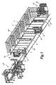
- the installation for the cooking of food items is the type consisting of numerous cooking tanks 1 for receiving the food items to be cooked, together with the means for loading/unloading 2 the food items to/from the said cooking tanks 1. They are fitted with the means for conveying, driving and storing the liquids, which are described in detail below with reference to Figure 11 , for the selective and independent filling of each of the said cooking tanks 1 with liquids for the purpose of subjecting the food items they contain to successive baths for different periods of times and at different temperatures, with at least one of the said baths for cooking and for optionally returning the said liquids to their respective tanks.
- Each of the said cooking tanks 1 consists of at least one side opening 3 with the means for being hermetically sealed, through the side opening 3 the food items can be loaded/unloaded by the said means of loading/unloading 2, which consist of at least one transport/lift trolley 6 equipped with the means of handling capable of holding, raising and lowering a batch of food items and transferring said batch into one of the cooking tanks 1, or to remove it from the same tank through the opening 3.
- Figure 1 shows two of the said trolleys 6, which move under their own power over rails 10 along the length of a path.
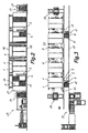
- the cooking tanks 1 are arranged forming a row along one side of the said path, with their side openings 3 aligned in a plane parallel to the same.
- the trolleys 6 can make selective stops in front of any of the cooking tanks 1 in order to introduce or remove a batch of food items from the tank under the control of programmable electronic means.
- the shown installation includes a demoulding station 13 at one end, for the demoulding and distribution of cooked food items in the cooking tanks I by batches in stacked moulds 11, as will described later, although it could just a easily be an unloading station for receiving and distributing the food items cooked in batches according to other forms of loading.
- the rails 10 extend to the said demoulding station 13, so that the trolley 6 is able to remove and transport the said batches of cooked food items from any of the cooking tanks 1 to the demoulding station 13.
- the installation also includes at least one storage station 14 of loading platforms 24, which can be accessed by the trolleys 6 moving along the rails 10. These loading platforms are used for handling the batches and their description is also provided later.
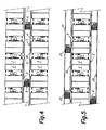
- Figure 4 shows a distribution variant in which the cooking tanks 1 are arranged to form a second row facing the first one along the length of the side opposite the said path, with the openings 3 of the said second row also aligned in a plane parallel to the path.
- the cooking tanks 1 in both rows can be loaded/unloaded by the said transport/lifting trolleys 6, moving along a single path over the rails 10.
- Figure 5 shows the cooking tanks 1 include a second opening 18 on the side opposite the first opening 3, with the said second openings 18 aligned in a plane parallel to a second path along which a second set of transport/lifting trolleys 19 move.
- the cooking tanks 1 can be loaded/unloaded, without distinction, by each of the first and second openings 3 and 18, or preferably, loaded by means of one opening and unloaded by the other, for example, trolleys 6 moving along the first path always carry out loading operations via the first openings 3 and the trolleys 19, which move along the second path always perform unloading operations via the second set of openings 18.
- each of the side openings 3 consist of a closing panel 17 that extends in a substantially vertical plane and is able to cover the opening, with is delimited by a frame 16, which is joined to the cooking tank 1.
- the cited closing panel 17 has a lateral movement in the manner of a sliding door, in order to allow/prevent entry inside the cooking tanks 1 together with frontal movement towards the said frame 16 that surrounds this side opening in the tank in order to apply pressure to the means of hermetically sealing the tank between the closing panel 17 and the frame 16.
- the opening 3 is fitted with the means of being hermetically sealed that consists of a device (not shown) to fix the closing panel 17 in place in a closed position, applying sufficient pressure against the said means of sealing, together with the means of locking the closing panel 17 in the said closed position, controlled by a safety system, to prevent it from being opened while the internal conditions are not suitable, in other words, while there is still liquid inside the cooking tank 1.
- the cited safety system is a double safety system consisting of, for example, a mechanical device and an auxiliary device.
- a suitable mechanical safety device would be a float (not shown) located close to the bottom of the cooking tank 1, where the float would prevent the closing panel 17 from being opened when there is a minimum amount of liquid remaining in the cooking tank 1.
- a level sensor may be employed which detects the presence of liquid inside the cooking tank 1 and generates a signal to block the opening of the closing panel 17 if the said presence of liquid is detected in the tank.
- the cooking tanks are installed side-by-side so that between each group of two cooking tanks 1 there is a separation space 4 with sufficient width to allow at least one complete opening movement of the closing panel 17 of opening 3 for one of the cooking tanks 1 adjacent to one of the said separation spaces 4.
- These separation spaces 4 also serve to house same of the said means of conveying, driving and storing the liquids and associated with inlet/outlet pipes for liquids to and from the cooking tank 1 through the said free side wall 5 of each cooking tank 1 adjacent to the separation space 4.
- the rows may include an indefinite number of tanks 1, and at the ends of the rows there may be a single tank, which, in this case, will preferable have the free side wall 5 adjacent to a separation space 4, or group of two tanks 1, in which case, the free side wall 5 of the last tank will be exposed and eventually fitted with a protective screen or casing (not shown) for its associated components.
- the trolley 6 includes the means of handling, which permit it to hold, raise and lower a batch of food items, and to transfer or remove the said batch to/from a cooking tank 1, in addition to the self-propelled translation movement of trolley 6 along the length of the rails 10.
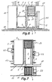
- the said means of handling consist of a horizontal support element 21 connected to a vertical lift device 22, together with transversal guides 20 mounted on the said horizontal support element 21.
- the cited lift device 22 is able to place the said horizontal support element 21 at various suitable heights so that the said transversal guides 20 can be aligned with some corresponding guides 7 installed on one or more levels inside the cooking tank 1.
- the said transversal guides 20 for the means of handling the trolley 6 are associated with the means of drive 23 that cooperate with the means of drive 8 associated with the said cooking tank 1 guides 7 for introducing or removing a batch of food items into/from the same.
- the means of drive 8 for the guides 7 are driven by geared-motors 15 located outside on the said free side wall 5 of each cooking tank 1, for example, supported on the said free side wall 5 on each one, where the free side wall 5 is, in general, adjacent to one of the separation spaces 4.
- These geared-motors 15 are coupled to the means of drive 8 through the said free side walls 5 by of adequate means of dynamic sealing.
- the installation consists of numerous loading platforms 24 adapted for use by the means of handling the trolley 6 described above.
- the cited loading platforms have a specific configuration suitable for coupling by the said means of drive 8 and 23.
- the loading platforms 24 act in the way of pallets, so that a batch of food items can be loaded on each one, whether in stacked moulds 11 or in a cage 12 ( Figure 9 ), in which the food items are arranged in moulds, packages or individual wrappers, separated into layers by separator plates as is normal in the sector's techniques.
- the batches are loaded into stacked moulds 11 and a demoulding station 13 is included at one end of the rails 10, together with one or two loading platform 24 storage stations 14 at the end of the row or rows of cooking tanks 1.
- a demoulding station 13 is included at one end of the rails 10, together with one or two loading platform 24 storage stations 14 at the end of the row or rows of cooking tanks 1.
- an installation prepared to handle the batches of food items loaded into cages would have, for example, a reception, unloading and distribution station, instead of the demoulding station, but would similarly have one or more loading platform 24 storage stations 14.
- Figure 10 shows a circulation diagram for the liquids in the installation of this invention.
- the installation consists of the means of heating the liquid (not shown) associated with a heated liquid tank 51, the means of cooling the liquid (not shown) associated with a cooling liquid tank 52 and the mains water supply connection 53.
- the common water is a liquid that is suitable for use as a heating liquid and a cooling liquid in the installation of this invention, with it being preferable to optionally add antifreeze, such as glycol, to the water that is employed as a cooling liquid in order to lower its freezing point.
- antifreeze such as glycol
- the cited heated liquid tanks 51 and that of the cooling liquid 52 have their respective outlets connected via their respective pumps 65 and 73a to the corresponding heated liquid manifold 59 and cooled liquid manifold 60, and the said mains water supply connection 53 is connected to a mains water supply manifold 61.
- a heated liquid collection pipe 62 leads to an inlet to the heated liquid tank 51
- a cooled liquid collecting pipe 63 leads to an inlet to the cooled liquid tank 52.
- the distribution pipes 59, 60, 61 and collector pipes 62 and 63 run along the length of the installation and supply liquids to each of the cooking tanks 1 and collect the liquids emptied from the same tanks in order to recycle them back to their respective tanks.
- Figure 10 only shows the diagram for a single tank, which is repeated for the other cooking tanks 1.
- connection 64 is taken from the cooled liquid manifold 60 directly to inlet 70 on cooking tank 1, and on which connection 64 is mounted a cooled liquid inlet valve 66.
- a connection 67 is taken from the heated liquid manifold 59 and leads to manifold valve 69, with a connection 68 which is taken from mains water supply manifold 61, from which a single pipe is taken to another inlet 71 on the cooking tank 1 via an inlet valve 72.
- the cooking tank 1 includes a steam inlet branch 57, which is derived from a steam manifold 80 connected to a steam source and with a duly controlled valve 58 in order to mix the steam, with heated liquid from the said heated water tank 51, mains water from the said mains water supply connection 53 or a mixture of them, inside the cooking tank 1 in order to raise its temperature to a required level under the control of some programmable electronic means.
- the steam is taken through a series of strategically positioned perforated pipes 74, through which the steam bubbles into the liquid that is present in the cooking tank.
- a pre-cook bath may be produced by filling the cooking tank 1 with mains water at environmental temperature and then raising the temperature inside the tank be bubbling steam through until an adequate level of approximately 50-60°C, or a cooking bath by filling the cooking tank with liquid previously heated by the means of heating to approximately 40-50°C and then raising the temperature inside the cooking tank 1 by bubbling steam through until a suitable value of approximately 70-80°C is attained.
- the use of steam to complete the heating of the liquid in the cooking tank involves a considerable savings in energy costs with respect to a system that completely heats the liquid by conventional means and maintains it at the required temperature in the heated liquid tank 51.
- the cooking tank has an outlet 75 connected to a first distribution valve 56 via drive pump 55.
- a branch connection 76 leaves the said distribution valve 56 and is connected to the said cooled liquid manifold 63 and another branch connection 77 that leads to a second distribution valve 78 from which branch connection 79 leaves and is connected to the said heated liquid manifold 62 and another branch connection 54 that leads back to the cooking tank 1 liquid inlet 71.
- the liquid that leaves the cooking tank 1 can be returned to the cooled liquid tank 52 by the cooled liquid manifold 63, can be returned to the heated liquid tank 51 by the heated liquid manifold 62 or can be recycled back to the cooking tank 1 inlet 71.
- the latter is especially useful when using heated liquid that is subjected to steam action in order to obtain a uniform temperature throughout the liquid inside the tank, thus avoiding possible differences of temperature in the various tank zones.
- a drain outlet 81 fitted with a valve 82 is included for the situation in which it is necessary to empty the tank without returning the liquid to any of the tanks.
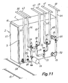
- Figure 11 shows a free wall 5 of a cooking tank 1, on which the cited geared motor assemblies 15 are installed for the drive means 8 associated with the guides 7 (see Figure 8 ), together with some of the cited means of conveying, driving and storing the liquids and steam.
- a steam manifold pipe 80 can be seen above the cooking tank, from which the steam inlet branch connection 57 leaves and is connected to a steam inlet via valve 58 and the said cooled liquid manifold pipe 60 that leaves the cited branch connection 64 that is connected to the said inlet 70 via valve 66.
- the heated liquid manifold pipe 59 and mains water 61 can also be seen and from which the respective branch connections 67 and 68 leave and that are connected to the cited inlet 72 via manifold valve 69.
- Tanks 51 and 52 and pumps 65 and 73 are not shown in Figure 11 .
- the liquid outlet 75 is connected by means of the pump 55 to the first distribution valve 56 from which branch connection 76 leaves to be connected to the cited cooled liquid manifold 63 and the other branch connection 77 that leads to the cited second distribution valve 78 from which branch connection 79 leaves and is connected to the cited heated liquid manifold 62 and branch connection 54 , which leads back to liquid inlet 71 on the cooking tank 1 in order to establish a liquid recirculation system.
- Another outlet 81 is connected to a sump via a valve 82.
- the distributor pipes 59, 60, 61 and 80 and the collector pipes 62 and 63 run along the length of the installation above the cooking tanks 1, and each cooking tank 1 has an equivalent layout of components connected to them.
Landscapes
- Life Sciences & Earth Sciences (AREA)
- Engineering & Computer Science (AREA)
- Wood Science & Technology (AREA)
- Zoology (AREA)
- Chemical & Material Sciences (AREA)
- Food Science & Technology (AREA)
- Polymers & Plastics (AREA)
- Commercial Cooking Devices (AREA)
Claims (19)
- Anlage zum Kochen von Lebensmitteln, umfassend:mehrere Kochbehälter (1) zum Aufnehmen von Lebensmitteln, die gekocht werden sollen;Mittel (2) zum Laden/Entladen der Lebensmittel in/von den genannten Kochbehältern (1);Mittel zum Erhitzen einer mit einem Behälter (51) für erhitzte Flüssigkeit verbundenen Flüssigkeit;Mittel zum Abkühlen einer mit einem Behälter (52) für abgekühlte Flüssigkeit und einem Anschluss mit einer Wasserversorgung (53) verbundenen Flüssigkeit;Mittel zum Fördern, Treiben und Zurückhalten von Flüssigkeiten, welche den genannten Behälter (51) für erhitzte Flüssigkeit, den genannten Behälter (52) für abgekühlte Flüssigkeit und die genannte Wasserversorgung (53) mit jedem der genannten Kochbehältern (1) verbindet;so dass jeder der genannten Kochbehältern (1) unabhängig mit den genannten Flüssigkeiten gefüllt werden kann und diese daraus herausgenommen werden können, wobei die Flüssigkeiten zu ihren jeweiligen Behältern (51, 52) zurückgebracht werden können, und wobei die enthaltenen Lebensmitteln in den Kochbehältern (1) aufeinander folgenden Bädern während verschiedenen Zeiträumen und bei verschiedenen Temperaturen ausgesetzt werden können, wobei mindestens einer der genannten Bäder ein Kochbad und ein Anderer zum Abkühlen ist, dadurch gekennzeichnet, dass jeder der genannten Kochbehälter (1) mindestens eine Seitenöffnung (3) mit Mitteln für ihren hermetischen Verschluss umfasst, so dass die Lebensmittel durch die genannte mindestens eine Seitenöffnung (3) von den genannten Mitteln (2) zum Laden/Entladen geladen/entladen werden, dass sich die genannten Mittel zum Laden/Entladen entlang mindestens einer Bahn bewegen, wobei die genannten Kochbehälter dafür angeordnet sind, mindestens eine Reihe entlang der Strecke von mindestens einer Seite der genannten Bahn zu bilden, wobei die Seitenöffnungen (3) derselben in einer Ebene parallel zu dieser Bahn ausgerichtet sind, und dass die genannten Mittel für den hermetischen Verschluss der genannten mindestens einen Seitenöffnung (3) eine Vorrichtung aufweisen, um eine wesentlich vertikale Abschlussplatte (17) in einer geschlossenen Stellung festzulegen, wobei ein geeigneter Druck gegen den genannten Mitteln für den hermetischen Verschluss und gegen Verriegelungsmitteln für die Verriegelung der genannten Platte (17) in der genannten geschlossenen Stellung angewendet wird, wodurch verhindert wird, dass sie sich öffnet, wenn die Umgebungsbedingungen innerhalb des Behälters ungeeignet sind.
- Anlage zum Kochen von Lebensmitteln nach Anspruch 1, dadurch gekennzeichnet, dass sich die genannte mindestens eine Seitenöffnung (3) über den größten Teil der mindestens einen Behälterseitenwand in der genannten Ebene parallel zur genannten Bahn erstreckt.
- Anlage nach Anspruch 1, dadurch gekennzeichnet, dass die genannten Mittel für den hermetischen Verschluss aus der gleitenden Abschlussplatte (17) bestehen, welche sich in einer wesentlich vertikalen Ebene erstreckt, wobei die genannte Abschlussplatte (17) eine Seitwärtsbewegung aufweist, um den Eintritt in die Kochbehälter zu ermöglichen/verhindern, zusammen mit einer frontalen Bewegung zu einem Gerüst (16), welches die genannte Seitenöffnung (3) in dem Behälter (1) umgibt, um einen Druck auf die Mittel für den hermetischen Verschluss des Behälters zwischen der Abschlussplatte (17) und dem Gerüst (16) anzuwenden.
- Anlage nach Anspruch 3, dadurch gekennzeichnet, dass die genannten Mittel für den hermetischen Verschluss der Öffnung (3) auch aus einer Vorrichtung bestehen, welche die Abschlussplatte (17) in einer geschlossenen Stellung festlegt, wobei ein geeigneter Druck gegen den genannten Mitteln für den hermetischen Verschluss und den Mitteln für die Verriegelung derselben angewendet wird, unter Kontrolle von mindestens einem Sicherheitssystem, um die Abschlussplatte (17) in der genannten geschlossenen Stellung zu verriegeln und um zu verhindern, dass sie sich öffnet, wenn die Umgebungsbedingungen innerhalb des Behälters ungeeignet sind.
- Anlage nach Anspruch 4, dadurch gekennzeichnet, dass das genannte Sicherheitssystem aus einem Schwimmer besteht, welcher sich in der Nähe des Bodens des Kochbehälters (1) befindet, wobei der Schwimmer die Öffnung der Abschlussplatte (17) verhindert, wenn noch eine minimale Menge an Flüssigkeit in dem Kochbehälter (1) übrig bleibt.
- Anlage nach Anspruch 5, dadurch gekennzeichnet, dass sie aus einer Hilfssicherheitsvorrichtung besteht, welche Mittel für die Erkennung der Anwesenheit von Flüssigkeit innerhalb des Kochbehälters (1) aufweist, wobei die Mittel für die Erkennung die Öffnung der Abschlussplatte (17) blockieren, wenn in dem Behälter eine solche Anwesenheit von Flüssigkeit erkannt wird.
- Anlage nach Anspruch 3, dadurch gekennzeichnet, dass die genannten Mittel (2) zum Laden/Entladen, zum Laden/Entladen der Lebensmitteln in/von den genannten Kochbehältern (1) aus mindestens einem Förder-/Hubwagen (6) bestehen, welcher mit Bedienungsmitteln versehen ist, die eine Lebensmittelpartie greifen, heben und herunterlassen können und die genannte Lebensmittelpartie innerhalb eines der Kochbehälter (1) bei einem bestimmten Niveau übergeben oder diese durch die genannte Öffnung (3) entnehmen können, wobei sich der Förder-/Hubwagen (6) entlang mindestens einer Bahn entlang der Strecke von mindestens einer Seite entlang welcher die genannten Kochbehälter (1) angeordnet sind, bewegt, unter Bildung von mindestens einer Reihe, wobei die Öffnungen (3) in einer Ebene parallel zur genannten Bahn ausgerichtet sind.
- Anlage nach Anspruch 7, dadurch gekennzeichnet, dass die genannten Kochbehälter (1) auch dazu angeordnet sind, eine zweite Reihe zu bilden, welche der Ersten zugewandt ist, entlang der Strecke der der genannten Bahn entgegengesetzten Seite, wobei die Öffnungen (3) der genannten zweiten Reihe auch in einer Ebene parallel zur genannten Bahn ausgerichtet sind, so dass die Kochbehälter (1) in beiden Reihen von dem genannten Förder-/Hubwagen (6) geladen/entladen werden können, von dem es mindestens einen gibt.
- Anlage nach Anspruch 7, dadurch gekennzeichnet, dass jeder der genannten Kochbehälter (1) eine zweite Öffnung (18) auf der zur ersten Öffnung (3) entgegengesetzten Seite aufweist, wobei die genannten zweiten Öffnungen (18) in einer Ebene parallel zu einer zweiten Bahn ausgerichtet sind, entlang welcher sich mindestens ein zweiter Förder-/Hubwagen (19) bewegt, so dass die Kochbehälter (1) durch jede der ersten und zweiten Öffnungen (3, 18) gleich geladen/entladen oder durch Eine geladen und durch die Andere entladen werden können.
- Anlage nach Anspruch 7, dadurch gekennzeichnet, dass die genannten Kochbehälter, mindestens in einem Zwischenbereich der genannten Reihe, zu zweit gruppiert sind, wobei jeder Kochbehälter (1) eine freie Seitenwand (5) mit Trennungsräumen (4) aufweist, welche zwischen jeder Zweiten der genannten freien Seitenwänden (5) gebildet sind, breit genug, um mindestens eine volle Öffnungsbewegung der Abschlussplatte (17) für die Öffnung (3) eines der Kochbehälter (1) zu ermöglichen, welcher an einen der genannten Trennungsräumen (4) angrenzt, wobei einige der genannten Mittel für die Förderung, Bewegung und Lagerung von Flüssigkeiten auf der freien Seitenwand (5) jedes Kochbehälters (1) angeordnet und in Verbindung mit Eintritts- und Austrittsröhren für Flüssigkeit zum Kochbehälter (1) durch die genannte freie Seitenwand (5) sind.
- Anlage nach Anspruch 7, dadurch gekennzeichnet, dass der genannte Wagen (6), von dem es mindestens einen gibt, selbstfahrend ist und sich auf Schienen (10) entlang der genannten Bahn bewegt und bestimmte Halte vor einem der Kochbehälter (1) machen kann, Wagen (6) welcher für die Einführung oder Entnahme einer Lebensmittelpartie unter Kontrolle von programmierbaren elektronischen Mitteln gewählt wird.
- Anlage nach Anspruch 7, dadurch gekennzeichnet, dass die genannten Bedienungsmittel in Verbindung mit dem Wagen (6) zum Greifen, Heben und Herunterlassen einer Lebensmittelpartie und zum Einführen oder Entnehmen der genannten Partie von einem Kochbehälter (1) aus einem horizontalen Stützelement (21) bestehen, welches an einer vertikalen Hubvorrichtung (22) angeschlossen ist, zusammen mit transversalen Führungen (20), welche auf dem genannten horizontalen Stützelement (21) montiert sind, wobei die genannte Hubvorrichtung (22) das genannte horizontale Stützelement (21) auf verschiedenen geeigneten Höhen anbringen kann, so dass die genannten transversalen Führungen (20) mit einigen entsprechenden Führungen (7) ausgerichtet sind, welche auf einem oder mehreren Niveaus innerhalb des Kochbehälters (1) installiert sind.
- Anlage nach Anspruch 12, dadurch gekennzeichnet, dass die genannten transversalen Führungen (20) für die Bedienungsmittel für den Wagen (6) mit den Bewegungsmitteln (23) verbunden sind, welche mit den Bewegungsmitteln (8) zusammenarbeiten, die mit den genannten Führungen (7) des Kochbehälters (1) verbunden sind, für die Einführung oder Entnahme einer Lebensmittelpartie in denselben/von demselben.
- Anlage nach Anspruch 13, dadurch gekennzeichnet, dass die genannten Bewegungsmittel (8) für die Führungen (7) von Motoren (15) bewegt werden, welche sich außerhalb jedes Kochbehälters (1) befinden, wobei die genannten Motoren (15) an den Bewegungsmitteln (8) durch eine der genannten freien Seitenwänden (5) mittels auf geeignete Weise abgedichteten dynamischen Mitteln angekoppelt sind.
- Anlage nach Anspruch 13, dadurch gekennzeichnet, dass sie aus zahlreichen Ladeflächen (24) besteht, welche dazu angepasst sind, von den Bedienungsmittel für den Wagen (6) verwendet zu werden, wobei sie eine Ausbildung aufweist, welche für die Ankopplung von den genannten Bewegungsmitteln (8, 23) über jede der Ladeflächen (24), auf denen eine Lebensmittelpartie deponiert werden kann, geeignet ist, entweder in gestapelten Formen (11) angeordnet oder unter Verwendung eines Käfigs (12), in welchen die Lebensmittel in Formen, Packungen oder individuellen Verpackungen angeordnet werden, welche in der Regel in Lagen mit Abstandsplatten getrennt sind.
- Anlage nach Anspruch 15, dadurch gekennzeichnet, dass sie eine Entformungsstation (13) zur Entformung der in den Kochbehältern (1) gekochten Lebensmitteln als Partien von gestapelten Formen (11) aufweist, wobei sich die genannten Schienen (10) zur genannten Entformungsstation (13) hin erstrecken, so dass der Wagen (6) die genannten Partien von gekochten und abgekühlten Lebensmitteln von jedem der Kochbehältern (1) zur Entformungsstation (13) entnehmen und fördern kann.
- Anlage nach Anspruch 15, dadurch gekennzeichnet, dass sie mindestens eine Lagerungsstation (14) für Ladeflächen (24) aufweist, welche für den sich entlang den Schienen (10) bewegenden Wagen (6) zugänglich ist.
- Anlage nach Anspruch 1, dadurch gekennzeichnet, dass jeder Kochbehälter (1) mindestens einen Dampfeintritt (57) aufweist, welcher mit einer Dampfversorgung durch ein Ventil (58) angeschlossen ist, Ventil, welches gesteuert ist, um Dampf entweder mit einer erhitzen Flüssigkeit von dem genannten Behälter (51) für erhitzte Flüssigkeit oder mit Leitungswasser von dem genannten Wasserversorgungsanschluss (53) oder einer Mischung derselben innerhalb des Kochbehälters (1) zu mischen, um die Temperatur auf das erforderliche Niveau unter Kontrolle von programmierbaren elektronischen Mitteln zu erhöhen.
- Anlage nach Anspruch 1, dadurch gekennzeichnet, dass sie Mittel zur Umwälzung der Flüssigkeit aufweist, unter Betätigung einer Pumpe (55) zwischen einem Austritt (75) und einem Eintritt (71) an dem Kochbehälter (1), um eine homogene Temperaturerhöhung innerhalb des Behälters zu bewirken und auf diese Weise jenen möglichen Unterschied in den verschiedenen Bereichen desselben zu verhindern.
Applications Claiming Priority (3)
| Application Number | Priority Date | Filing Date | Title |
|---|---|---|---|
| ES200201147A ES2197816B1 (es) | 2002-05-20 | 2002-05-20 | Instalacion para la coccion de alimentos. |
| ES200201147 | 2002-05-20 | ||
| PCT/ES2003/000229 WO2003096815A1 (es) | 2002-05-20 | 2003-05-20 | Instalación para la cocción de alimentos |
Publications (2)
| Publication Number | Publication Date |
|---|---|
| EP1510132A1 EP1510132A1 (de) | 2005-03-02 |
| EP1510132B1 true EP1510132B1 (de) | 2012-07-11 |
Family
ID=29433282
Family Applications (1)
| Application Number | Title | Priority Date | Filing Date |
|---|---|---|---|
| EP03727510A Expired - Lifetime EP1510132B1 (de) | 2002-05-20 | 2003-05-20 | Anlage zum kochen von lebensmitteln |
Country Status (6)
| Country | Link |
|---|---|
| US (1) | US7654194B2 (de) |
| EP (1) | EP1510132B1 (de) |
| AR (1) | AR039834A1 (de) |
| AU (1) | AU2003233800A1 (de) |
| ES (2) | ES2197816B1 (de) |
| WO (1) | WO2003096815A1 (de) |
Cited By (1)
| Publication number | Priority date | Publication date | Assignee | Title |
|---|---|---|---|---|
| ITUB20155734A1 (it) * | 2015-11-20 | 2016-02-20 | Food Service S N C Di Breda Matteo & C | Sistema di cottura con successivo abbattimento della temperatura di alimenti e relativo metodo di cottura di alimenti |
Families Citing this family (10)
| Publication number | Priority date | Publication date | Assignee | Title |
|---|---|---|---|---|
| ITMI20032014A1 (it) * | 2003-10-16 | 2005-04-17 | Sinteco Impianti S R L | Apparecchiatura per la cottura ed il raffreddamento in continuo in acqua di prodotti alimentari in genere e di prodotti carnei in particolare |
| EP1747729B1 (de) | 2004-05-13 | 2013-11-27 | Metalquimia, S.A. | System und verfahren zur immersionsgarung/kühlung von nahrungsmitteln in diffuser zwangskonfektion |
| FR2934121B1 (fr) * | 2008-07-23 | 2010-09-10 | Armor Inox Sa | Procede de cuisson et de refroidissement de produits alimentaires, et installation pour la mise en oeuvre dudit procede |
| JP5909195B2 (ja) * | 2010-01-29 | 2016-04-26 | トルガ・エルデン | ポッピングキャンディのための製造方法および装置 |
| WO2013130798A1 (en) | 2012-02-29 | 2013-09-06 | Nomiku Inc. | Apparatus and system for low-temperature cooking |
| CN104585303A (zh) * | 2015-01-20 | 2015-05-06 | 江苏裕灌现代农业科技有限公司 | 适用于蘑菇工艺的新型冷却槽 |
| US10440979B2 (en) * | 2015-11-11 | 2019-10-15 | Home Tech Innovation, Inc. | Apparatus and methods for at least semi-autonomous meal storage and cooking via fluid immersion |
| CN111372470A (zh) | 2017-09-15 | 2020-07-03 | 家庭技术创新股份有限公司 | 用于至少半自动化地贮存和烹饪膳食的设备和方法 |
| CN110861661B (zh) * | 2019-11-29 | 2020-11-06 | 中车青岛四方机车车辆股份有限公司 | 轨道车辆及其集装箱运输控制系统 |
| KR102187274B1 (ko) * | 2020-09-08 | 2020-12-04 | 박세근 | 생선 조리기 |
Family Cites Families (8)
| Publication number | Priority date | Publication date | Assignee | Title |
|---|---|---|---|---|
| FR2501491B1 (fr) * | 1981-03-13 | 1985-11-08 | Mariotti Rene | Friteuse industrielle |
| FR2509140A1 (fr) * | 1981-07-08 | 1983-01-14 | Armor Inox Sa | Procede et installation de cuisson, decongelation ou refroidissement de produits alimentaires et notamment de jambons |
| FR2615484B3 (fr) | 1987-05-19 | 1989-08-25 | Armor Inox Sa | Dispositif de support et recipients associes pour le chargement de produits alimentaires, notamment des jambons |
| FR2628962B1 (fr) * | 1988-03-23 | 1990-11-23 | Armor Inox Sa | Installation de cuisson |
| FR2662998A1 (fr) * | 1990-06-08 | 1991-12-13 | Beizermann Michel | Dispositif de conditionnement en continu de barquettes. |
| US5398600A (en) * | 1993-02-09 | 1995-03-21 | Madsen; Torben | Batch conveyor for processing chamber |
| IT1270062B (it) * | 1994-07-04 | 1997-04-28 | Rossi & Catelli Spa | Impianto per la produzione su scala industriale di alimenti cotti, a lunga conservazione pronti da consumare |
| FR2784547B1 (fr) * | 1998-10-19 | 2000-12-15 | Armor Inox Sa | Installation de cuisson |
-
2002
- 2002-05-20 ES ES200201147A patent/ES2197816B1/es not_active Expired - Fee Related
-
2003
- 2003-05-20 ES ES03727510T patent/ES2390164T3/es not_active Expired - Lifetime
- 2003-05-20 EP EP03727510A patent/EP1510132B1/de not_active Expired - Lifetime
- 2003-05-20 US US10/515,040 patent/US7654194B2/en not_active Expired - Fee Related
- 2003-05-20 WO PCT/ES2003/000229 patent/WO2003096815A1/es not_active Ceased
- 2003-05-20 AR ARP030101744A patent/AR039834A1/es active IP Right Grant
- 2003-05-20 AU AU2003233800A patent/AU2003233800A1/en not_active Abandoned
Cited By (1)
| Publication number | Priority date | Publication date | Assignee | Title |
|---|---|---|---|---|
| ITUB20155734A1 (it) * | 2015-11-20 | 2016-02-20 | Food Service S N C Di Breda Matteo & C | Sistema di cottura con successivo abbattimento della temperatura di alimenti e relativo metodo di cottura di alimenti |
Also Published As
| Publication number | Publication date |
|---|---|
| ES2197816A1 (es) | 2004-01-01 |
| ES2197816B1 (es) | 2005-03-16 |
| WO2003096815A1 (es) | 2003-11-27 |
| AU2003233800A1 (en) | 2003-12-02 |
| EP1510132A1 (de) | 2005-03-02 |
| AR039834A1 (es) | 2005-03-02 |
| ES2390164T3 (es) | 2012-11-07 |
| US7654194B2 (en) | 2010-02-02 |
| US20060083836A1 (en) | 2006-04-20 |
Similar Documents
| Publication | Publication Date | Title |
|---|---|---|
| EP1510132B1 (de) | Anlage zum kochen von lebensmitteln | |
| US5281426A (en) | Method for heating and cooling sealed food product pouches | |
| US20100101430A1 (en) | Stackable mold unit for obtaining a molded cooked food product | |
| NL8500343A (nl) | Steriliseerwerkwijze en -inrichting. | |
| EP1747729B1 (de) | System und verfahren zur immersionsgarung/kühlung von nahrungsmitteln in diffuser zwangskonfektion | |
| EP1056360B1 (de) | Vorrichtung sowie verfahren zur pasteurisierung ungeschaelter eier | |
| US5992304A (en) | Apparatus for treatment of food products | |
| CA1327140C (en) | Cooking machine | |
| JPS6245594Y2 (de) | ||
| AU2001246613B2 (en) | Installation for continuous sterilisation of products contained in flexible packages | |
| CA2812911A1 (en) | Recirculating continuous storage apparatus | |
| US4861000A (en) | Installation having several elements for heat treatments | |
| EP3558829B1 (de) | Vorrichtung zur wärmeschrumpfung einer verpackung und verfahren zur wärmeschrumpfung einer verpackung | |
| US7846486B2 (en) | Pasteurization or sterilization method and device for carrying out same | |
| KR102695290B1 (ko) | 원료 자동 토출기 | |
| SU1431090A1 (ru) | Стеллажное хранилище | |
| CN220044782U (zh) | 用于魔芋灭菌的装置 | |
| NL2012876B1 (en) | Apparatus for thermally processing food packages comprising product carriers with positive package handling. | |
| KR102627234B1 (ko) | 선입선출식 자동원료공급장치 | |
| EP2748545B1 (de) | Vorrichtung zum einfrieren und zum lagern von organischem material und ein türmodul für eine solche vorrichtung | |
| US20150157033A1 (en) | Seafood Processing Apparatus and Methods of Processing Seafood | |
| US20260047721A1 (en) | Automated pressure fryer system | |
| CN201370057Y (zh) | 一种多级混合式快煮米设备 | |
| GB2442297A (en) | Food processing apparatus with liquid coolant supply and method | |
| JP3322636B2 (ja) | 固形食品素材加工方法及び固形食品素材加工装置 |
Legal Events
| Date | Code | Title | Description |
|---|---|---|---|
| PUAI | Public reference made under article 153(3) epc to a published international application that has entered the european phase |
Free format text: ORIGINAL CODE: 0009012 |
|
| 17P | Request for examination filed |
Effective date: 20041215 |
|
| AK | Designated contracting states |
Kind code of ref document: A1 Designated state(s): AT BE BG CH CY CZ DE DK EE ES FI FR GB GR HU IE IT LI LU MC NL PT RO SE SI SK TR |
|
| AX | Request for extension of the european patent |
Extension state: AL LT LV MK |
|
| DAX | Request for extension of the european patent (deleted) | ||
| 17Q | First examination report despatched |
Effective date: 20070907 |
|
| GRAP | Despatch of communication of intention to grant a patent |
Free format text: ORIGINAL CODE: EPIDOSNIGR1 |
|
| GRAS | Grant fee paid |
Free format text: ORIGINAL CODE: EPIDOSNIGR3 |
|
| GRAA | (expected) grant |
Free format text: ORIGINAL CODE: 0009210 |
|
| AK | Designated contracting states |
Kind code of ref document: B1 Designated state(s): AT BE BG CH CY CZ DE DK EE ES FI FR GB GR HU IE IT LI LU MC NL PT RO SE SI SK TR |
|
| REG | Reference to a national code |
Ref country code: GB Ref legal event code: FG4D |
|
| REG | Reference to a national code |
Ref country code: CH Ref legal event code: EP |
|
| REG | Reference to a national code |
Ref country code: AT Ref legal event code: REF Ref document number: 565589 Country of ref document: AT Kind code of ref document: T Effective date: 20120715 |
|
| REG | Reference to a national code |
Ref country code: IE Ref legal event code: FG4D |
|
| REG | Reference to a national code |
Ref country code: DE Ref legal event code: R096 Ref document number: 60341512 Country of ref document: DE Effective date: 20120830 |
|
| REG | Reference to a national code |
Ref country code: NL Ref legal event code: T3 |
|
| REG | Reference to a national code |
Ref country code: ES Ref legal event code: FG2A Ref document number: 2390164 Country of ref document: ES Kind code of ref document: T3 Effective date: 20121107 |
|
| REG | Reference to a national code |
Ref country code: AT Ref legal event code: MK05 Ref document number: 565589 Country of ref document: AT Kind code of ref document: T Effective date: 20120711 |
|
| PG25 | Lapsed in a contracting state [announced via postgrant information from national office to epo] |
Ref country code: FI Free format text: LAPSE BECAUSE OF FAILURE TO SUBMIT A TRANSLATION OF THE DESCRIPTION OR TO PAY THE FEE WITHIN THE PRESCRIBED TIME-LIMIT Effective date: 20120711 Ref country code: BE Free format text: LAPSE BECAUSE OF FAILURE TO SUBMIT A TRANSLATION OF THE DESCRIPTION OR TO PAY THE FEE WITHIN THE PRESCRIBED TIME-LIMIT Effective date: 20120711 Ref country code: AT Free format text: LAPSE BECAUSE OF FAILURE TO SUBMIT A TRANSLATION OF THE DESCRIPTION OR TO PAY THE FEE WITHIN THE PRESCRIBED TIME-LIMIT Effective date: 20120711 Ref country code: CY Free format text: LAPSE BECAUSE OF FAILURE TO SUBMIT A TRANSLATION OF THE DESCRIPTION OR TO PAY THE FEE WITHIN THE PRESCRIBED TIME-LIMIT Effective date: 20120711 |
|
| PG25 | Lapsed in a contracting state [announced via postgrant information from national office to epo] |
Ref country code: SI Free format text: LAPSE BECAUSE OF FAILURE TO SUBMIT A TRANSLATION OF THE DESCRIPTION OR TO PAY THE FEE WITHIN THE PRESCRIBED TIME-LIMIT Effective date: 20120711 Ref country code: GR Free format text: LAPSE BECAUSE OF FAILURE TO SUBMIT A TRANSLATION OF THE DESCRIPTION OR TO PAY THE FEE WITHIN THE PRESCRIBED TIME-LIMIT Effective date: 20121012 Ref country code: PT Free format text: LAPSE BECAUSE OF FAILURE TO SUBMIT A TRANSLATION OF THE DESCRIPTION OR TO PAY THE FEE WITHIN THE PRESCRIBED TIME-LIMIT Effective date: 20121112 Ref country code: SE Free format text: LAPSE BECAUSE OF FAILURE TO SUBMIT A TRANSLATION OF THE DESCRIPTION OR TO PAY THE FEE WITHIN THE PRESCRIBED TIME-LIMIT Effective date: 20120711 |
|
| PG25 | Lapsed in a contracting state [announced via postgrant information from national office to epo] |
Ref country code: DK Free format text: LAPSE BECAUSE OF FAILURE TO SUBMIT A TRANSLATION OF THE DESCRIPTION OR TO PAY THE FEE WITHIN THE PRESCRIBED TIME-LIMIT Effective date: 20120711 Ref country code: EE Free format text: LAPSE BECAUSE OF FAILURE TO SUBMIT A TRANSLATION OF THE DESCRIPTION OR TO PAY THE FEE WITHIN THE PRESCRIBED TIME-LIMIT Effective date: 20120711 Ref country code: RO Free format text: LAPSE BECAUSE OF FAILURE TO SUBMIT A TRANSLATION OF THE DESCRIPTION OR TO PAY THE FEE WITHIN THE PRESCRIBED TIME-LIMIT Effective date: 20120711 Ref country code: CZ Free format text: LAPSE BECAUSE OF FAILURE TO SUBMIT A TRANSLATION OF THE DESCRIPTION OR TO PAY THE FEE WITHIN THE PRESCRIBED TIME-LIMIT Effective date: 20120711 |
|
| PLBE | No opposition filed within time limit |
Free format text: ORIGINAL CODE: 0009261 |
|
| STAA | Information on the status of an ep patent application or granted ep patent |
Free format text: STATUS: NO OPPOSITION FILED WITHIN TIME LIMIT |
|
| PG25 | Lapsed in a contracting state [announced via postgrant information from national office to epo] |
Ref country code: SK Free format text: LAPSE BECAUSE OF FAILURE TO SUBMIT A TRANSLATION OF THE DESCRIPTION OR TO PAY THE FEE WITHIN THE PRESCRIBED TIME-LIMIT Effective date: 20120711 |
|
| 26N | No opposition filed |
Effective date: 20130412 |
|
| PG25 | Lapsed in a contracting state [announced via postgrant information from national office to epo] |
Ref country code: BG Free format text: LAPSE BECAUSE OF FAILURE TO SUBMIT A TRANSLATION OF THE DESCRIPTION OR TO PAY THE FEE WITHIN THE PRESCRIBED TIME-LIMIT Effective date: 20121011 |
|
| REG | Reference to a national code |
Ref country code: DE Ref legal event code: R097 Ref document number: 60341512 Country of ref document: DE Effective date: 20130412 |
|
| PG25 | Lapsed in a contracting state [announced via postgrant information from national office to epo] |
Ref country code: MC Free format text: LAPSE BECAUSE OF FAILURE TO SUBMIT A TRANSLATION OF THE DESCRIPTION OR TO PAY THE FEE WITHIN THE PRESCRIBED TIME-LIMIT Effective date: 20120711 |
|
| REG | Reference to a national code |
Ref country code: CH Ref legal event code: PL |
|
| GBPC | Gb: european patent ceased through non-payment of renewal fee |
Effective date: 20130520 |
|
| PG25 | Lapsed in a contracting state [announced via postgrant information from national office to epo] |
Ref country code: LI Free format text: LAPSE BECAUSE OF NON-PAYMENT OF DUE FEES Effective date: 20130531 Ref country code: CH Free format text: LAPSE BECAUSE OF NON-PAYMENT OF DUE FEES Effective date: 20130531 |
|
| REG | Reference to a national code |
Ref country code: IE Ref legal event code: MM4A |
|
| PG25 | Lapsed in a contracting state [announced via postgrant information from national office to epo] |
Ref country code: IE Free format text: LAPSE BECAUSE OF NON-PAYMENT OF DUE FEES Effective date: 20130520 Ref country code: GB Free format text: LAPSE BECAUSE OF NON-PAYMENT OF DUE FEES Effective date: 20130520 |
|
| PG25 | Lapsed in a contracting state [announced via postgrant information from national office to epo] |
Ref country code: TR Free format text: LAPSE BECAUSE OF FAILURE TO SUBMIT A TRANSLATION OF THE DESCRIPTION OR TO PAY THE FEE WITHIN THE PRESCRIBED TIME-LIMIT Effective date: 20120711 |
|
| PG25 | Lapsed in a contracting state [announced via postgrant information from national office to epo] |
Ref country code: HU Free format text: LAPSE BECAUSE OF FAILURE TO SUBMIT A TRANSLATION OF THE DESCRIPTION OR TO PAY THE FEE WITHIN THE PRESCRIBED TIME-LIMIT; INVALID AB INITIO Effective date: 20030520 Ref country code: LU Free format text: LAPSE BECAUSE OF NON-PAYMENT OF DUE FEES Effective date: 20130520 |
|
| REG | Reference to a national code |
Ref country code: FR Ref legal event code: PLFP Year of fee payment: 13 |
|
| REG | Reference to a national code |
Ref country code: FR Ref legal event code: PLFP Year of fee payment: 14 |
|
| PGFP | Annual fee paid to national office [announced via postgrant information from national office to epo] |
Ref country code: NL Payment date: 20160526 Year of fee payment: 14 |
|
| PGFP | Annual fee paid to national office [announced via postgrant information from national office to epo] |
Ref country code: ES Payment date: 20160527 Year of fee payment: 14 Ref country code: DE Payment date: 20160527 Year of fee payment: 14 |
|
| PGFP | Annual fee paid to national office [announced via postgrant information from national office to epo] |
Ref country code: FR Payment date: 20160530 Year of fee payment: 14 |
|
| PGFP | Annual fee paid to national office [announced via postgrant information from national office to epo] |
Ref country code: IT Payment date: 20160627 Year of fee payment: 14 |
|
| REG | Reference to a national code |
Ref country code: DE Ref legal event code: R119 Ref document number: 60341512 Country of ref document: DE |
|
| REG | Reference to a national code |
Ref country code: NL Ref legal event code: MM Effective date: 20170601 |
|
| REG | Reference to a national code |
Ref country code: FR Ref legal event code: ST Effective date: 20180131 |
|
| PG25 | Lapsed in a contracting state [announced via postgrant information from national office to epo] |
Ref country code: NL Free format text: LAPSE BECAUSE OF NON-PAYMENT OF DUE FEES Effective date: 20170601 |
|
| PG25 | Lapsed in a contracting state [announced via postgrant information from national office to epo] |
Ref country code: DE Free format text: LAPSE BECAUSE OF NON-PAYMENT OF DUE FEES Effective date: 20171201 |
|
| PG25 | Lapsed in a contracting state [announced via postgrant information from national office to epo] |
Ref country code: IT Free format text: LAPSE BECAUSE OF NON-PAYMENT OF DUE FEES Effective date: 20170520 Ref country code: FR Free format text: LAPSE BECAUSE OF NON-PAYMENT OF DUE FEES Effective date: 20170531 |
|
| REG | Reference to a national code |
Ref country code: ES Ref legal event code: FD2A Effective date: 20180710 |
|
| PG25 | Lapsed in a contracting state [announced via postgrant information from national office to epo] |
Ref country code: ES Free format text: LAPSE BECAUSE OF NON-PAYMENT OF DUE FEES Effective date: 20170521 |