EP1510257A2 - Hachoir - Google Patents
Hachoir Download PDFInfo
- Publication number
- EP1510257A2 EP1510257A2 EP04010642A EP04010642A EP1510257A2 EP 1510257 A2 EP1510257 A2 EP 1510257A2 EP 04010642 A EP04010642 A EP 04010642A EP 04010642 A EP04010642 A EP 04010642A EP 1510257 A2 EP1510257 A2 EP 1510257A2
- Authority
- EP
- European Patent Office
- Prior art keywords
- compressed air
- cutter
- seal
- working space
- knife shaft
- Prior art date
- Legal status (The legal status is an assumption and is not a legal conclusion. Google has not performed a legal analysis and makes no representation as to the accuracy of the status listed.)
- Granted
Links
Images



Classifications
-
- B—PERFORMING OPERATIONS; TRANSPORTING
- B02—CRUSHING, PULVERISING, OR DISINTEGRATING; PREPARATORY TREATMENT OF GRAIN FOR MILLING
- B02C—CRUSHING, PULVERISING, OR DISINTEGRATING IN GENERAL; MILLING GRAIN
- B02C18/00—Disintegrating by knives or other cutting or tearing members which chop material into fragments
- B02C18/06—Disintegrating by knives or other cutting or tearing members which chop material into fragments with rotating knives
- B02C18/065—Disintegrating by knives or other cutting or tearing members which chop material into fragments with rotating knives within rotatable bowls, e.g. meat cutters
-
- B—PERFORMING OPERATIONS; TRANSPORTING
- B02—CRUSHING, PULVERISING, OR DISINTEGRATING; PREPARATORY TREATMENT OF GRAIN FOR MILLING
- B02C—CRUSHING, PULVERISING, OR DISINTEGRATING IN GENERAL; MILLING GRAIN
- B02C18/00—Disintegrating by knives or other cutting or tearing members which chop material into fragments
- B02C18/06—Disintegrating by knives or other cutting or tearing members which chop material into fragments with rotating knives
- B02C18/16—Details
Definitions
- the invention relates to a cutter according to Preamble of claim 1.
- Cutters are well-known machines for cutting and mixing food, especially in the case of Sausage production used to produce sausage meat become.
- a drivable knife shaft protrudes into the Working space of the cutter, in which a bowl rotatably arranged is its content by the on the knife shaft arranged knife is acted upon in the rotation thereof.
- labyrinth seals used the knife shaft bearing and before this arranged lip seals, which with regular Harden contact with meat and lose its sealing effect can protect against the fry.
- a labyrinth seal is described by Part of the centrifugal force should be self-cleaning.
- Cutters can work with atmospheric pressure in the working space or can be configured as a so-called vacuum cutter be, in which the working space is airtight and closed can be partially evacuated. Such cutters can be operated without vacuum generation.
- vacuum cleaner of the company. Tipper Tie Alpina, Gossau, Switzerland, is at the front of the knife shaft bearing arranged lip seal to their relief provided by the negative pressure line, the Space between the lip seal and the labyrinth seal connects with the environment, so in this Room normal ambient pressure prevails. In vacuum operation of the cutter therefore passes through the negative pressure of max. 1 bar in the working space air through the labyrinth seal through into the workroom.
- the invention is based on the object improved protection of the knife shaft bearing create.
- the cutter has a source (pump) for compressed air or an external connection to one Compressed air source and the pipe in the room at the seal
- This room faces you on one opposite Atmospheric pressure higher pressure, so that through the generation of this overpressure an air flow through the Sealing passes through into the working space.
- This Air flow largely prevents penetration of the working space processed good in the seal and prevents thus a penetration of the goods to the bearing seal, which is thus protected from the estate. The most extensive Keeping the seal from the material easier also cleaning the cutter.
- an inventive Kutter is in every mode of operation - both at a cutter without evacuation possibility of the working space as well as in a vacuum cutter both in vacuum operation as well as in operation without vacuum generation - always an air flow through the seal into the working space enforceable by means of the overpressure in the room, whereby the advantages mentioned are achievable.
- the seal is a labyrinth seal.
- the relatively small columns of such Sealing result in a low air flow with good Pollution prevention.
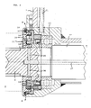
- FIG. 1 is a part of a cutter 1 shown, wherein a part of the Machine frame 2 with the boom 7 'and the blade shaft 3 (shown interrupted) and in particular the Storage 10, 20 of the cutter shaft 3 of the cutter can be seen are.
- the front end 6 protrudes the knife shaft 3 in the working space, not shown 4 of the cutter.
- the knife package 5 is fixed, which in the Drawing is indicated only with broken lines.
- This knife package processed in the arranged in the working space 4 Kutterschdorfl the material to be processed.
- the other End of the knife shaft is driven on also known manner, e.g.
- a seal which in Figure 1 only generally denoted by 13, and which is shown enlarged in Figure 2, is on entry the blade shaft provided in the working space 4, wherein the knife shaft through the working space limiting Wall 7 passes, which only indicated in the figures is.
- the seal 13 is intended to prevent that Good worked in the working space, which usually Wurstbetz is up to the camp 10 or until this upstream bearing seal 12 can reach here is designed as a lip seal.
- the Seal 13 as a labyrinth-like seal with the Divide 14 (fixed) and 15 (rotate with the knife shaft) executed, which meanders between them forming narrow gap 18 form.
- the illustrated Examples are also seals 16 from a Plastic or rubber material along the sealing gap intended.
- a Lubricant line 21 leads to the bearing 10.
- a room 11 in this example disposed between the bearing seal 12 and the seal 13 is, generates an overpressure, being under pressure a pressure greater than atmospheric pressure is understood.
- a line compressed air in the Room 11 is supplied.
- another gas mixture or a Pure gas is considered to be included, but usually becomes probably compressed air can be used.
- FIGS. 3 and 4 show a further embodiment, wherein in these figures again in FIG. 3 shows part of the cutter and FIG. 4 the entrance of the knife shaft in the working space increased is shown.
- Same reference numerals as before used refer to the same parts.
- the front Knife shaft bearing also takes place by means of the bearing 10, which in this case but by two working space side Bearing seals 12 in the form of lip seals is protected.
- the supply of compressed air into the room 11 takes place here via a line 30, which is not through the knife shaft leads, which is why the knife shaft 33 no has central bore.
- the compressed air is over a supplied to a separate line 30, which is e.g.
- the mode of action of the compressed air in the room 11 is the same in both embodiments shown.
- the seal 13 is permeable to air flows through the Compressed air through the annular gap 18 through the seal in the direction of the working space and enters around the working area out of the seal, what through the Arrow A in Figure 2 and Figure 4 is indicated.
- These by the pressure in room 11 forced air flow Effectively prevents the onset of meat in the seal during the operation of the cutter.
- the compressed air generating pump or the compressed air connection 26 is therefore preferably automatically every time the cutter is started up activated, so that always the air flow through the seal 13 is ensured.
- This airflow can be produced both in a vacuum cutter and can be used both in vacuum operation as well as in operation can be effective without vacuum in the work space and can also be produced at a cutter that is not for vacuum operation is designed.
- a labyrinth seal the type shown is a pressure of about 1.5 bar in the Room 11 suitable.
- the compressed air must be oil-free, which by appropriate design of the pump 25 and the compressed air source connected to port 26 is ensured can be.
- the embodiment is preferred the seal 13 as a labyrinth seal, possibly with additional sealing elements 16, as in the figures shown. Such a labyrinth seal results in a relatively low air flow.
- the room 11 can as shown between the bearing seal 12 and the seal 13 may be arranged.
Landscapes
- Engineering & Computer Science (AREA)
- Food Science & Technology (AREA)
- Sealing Using Fluids, Sealing Without Contact, And Removal Of Oil (AREA)
- Sealing With Elastic Sealing Lips (AREA)
Applications Claiming Priority (2)
| Application Number | Priority Date | Filing Date | Title |
|---|---|---|---|
| AT5942003U | 2003-08-29 | ||
| AT0059403U AT7173U1 (de) | 2003-08-29 | 2003-08-29 | Kutter |
Publications (3)
| Publication Number | Publication Date |
|---|---|
| EP1510257A2 true EP1510257A2 (fr) | 2005-03-02 |
| EP1510257A3 EP1510257A3 (fr) | 2006-03-01 |
| EP1510257B1 EP1510257B1 (fr) | 2016-04-27 |
Family
ID=32931959
Family Applications (1)
| Application Number | Title | Priority Date | Filing Date |
|---|---|---|---|
| EP04010642.9A Revoked EP1510257B1 (fr) | 2003-08-29 | 2004-05-05 | Hachoir |
Country Status (2)
| Country | Link |
|---|---|
| EP (1) | EP1510257B1 (fr) |
| AT (1) | AT7173U1 (fr) |
Cited By (1)
| Publication number | Priority date | Publication date | Assignee | Title |
|---|---|---|---|---|
| EP3584011A1 (fr) * | 2018-06-08 | 2019-12-25 | Fritsch GmbH | Broyeur à découper destiné au broyage par découpage des échantillons |
Family Cites Families (10)
| Publication number | Priority date | Publication date | Assignee | Title |
|---|---|---|---|---|
| DE825575C (de) * | 1949-11-01 | 1951-12-20 | Siemens Schuckertwerke A G | Elektromotor mit senkrechter Welle |
| GB1315309A (en) * | 1969-09-02 | 1973-05-02 | Rotax Ltd | Oil seal arrangements for rotary shafts |
| DE2050828A1 (en) * | 1970-10-16 | 1972-04-20 | Alexanderwerk Ag, 5630 Remscheid | Meat chopping machine - with compressed air bearing between flanges of cutter hood and cutter bowl |
| DE3509698A1 (de) | 1985-03-18 | 1986-09-18 | Krämer + Grebe GmbH & Co KG Maschinenfabrik, 3560 Biedenkopf | Labyrinth-abdichtung fuer kutter zum schneiden und mischen von lebensmittel, vorzugweise fuer die wurstherstellung |
| DE3831585A1 (de) * | 1988-09-16 | 1990-03-22 | Dueker Eisenwerk | Kutter zum schneiden und mischen einer lebensmittelmasse, insbesondere fuer die wurstherstellung |
| DE8814152U1 (de) | 1988-11-11 | 1990-03-22 | Ott Maschinentechnik GmbH, 8960 Kempten | Drehdurchführung für zwei unterschiedliche Fluide |
| DE9206010U1 (de) | 1992-05-11 | 1992-07-16 | Krämer + Grebe GmbH & Co KG Maschinenfabrik, 3560 Biedenkopf | Dichtungsanordnung |
| DE9215684U1 (de) * | 1992-11-17 | 1993-02-18 | Krämer + Grebe GmbH & Co KG Maschinenfabrik, 3560 Biedenkopf | Dichtungsanordnung für einen Schüsselkutter |
| DE19623217C2 (de) * | 1996-06-11 | 1999-03-25 | Loedige Maschbau Gmbh Geb | Aufschlußwerkzeug |
| DE10212808B4 (de) * | 2002-03-22 | 2004-07-29 | Westfalia Separator Ag | Separator |
-
2003
- 2003-08-29 AT AT0059403U patent/AT7173U1/de not_active IP Right Cessation
-
2004
- 2004-05-05 EP EP04010642.9A patent/EP1510257B1/fr not_active Revoked
Cited By (1)
| Publication number | Priority date | Publication date | Assignee | Title |
|---|---|---|---|---|
| EP3584011A1 (fr) * | 2018-06-08 | 2019-12-25 | Fritsch GmbH | Broyeur à découper destiné au broyage par découpage des échantillons |
Also Published As
| Publication number | Publication date |
|---|---|
| AT7173U1 (de) | 2004-11-25 |
| EP1510257B1 (fr) | 2016-04-27 |
| EP1510257A3 (fr) | 2006-03-01 |
Similar Documents
| Publication | Publication Date | Title |
|---|---|---|
| DE19520982B4 (de) | Trommelhackanlage | |
| CH688339A5 (de) | Drahtfuehrungsvorrichtung fuer eine Funkenerosionsmaschine. | |
| EP3448164B1 (fr) | Outil d'aspiration ainsi que dispositif et procédé pour éviscérer des poisons ouverts dans la cavité abdominale | |
| EP3670920A1 (fr) | Mécanisme de coupe pour une pompe immergée à eaux usées | |
| DE102017116777B3 (de) | Zerkleinerungsmaschine | |
| EP1510257B1 (fr) | Hachoir | |
| DE69513894T2 (de) | Aufnahmeeinrichtung für stabförmige Gegenstände | |
| DD219094A5 (de) | Feldhaecksler | |
| DE202007015665U1 (de) | Hackmaschine | |
| AT501975B1 (de) | Feststehendes messer für eine hackmaschine | |
| DE202013011613U1 (de) | Einrichtung zum Verpacken von Brotscheiben inBrotschneidemaschinen | |
| DE102005062644A1 (de) | Schneidvorrichtung und Strangmaterialabfördervorrichtung der Tabak verarbeitenden Industrie | |
| DE19506415C1 (de) | Vorrichtung zum Verarbeiten von Nahrungsmitteln | |
| EP0176678B1 (fr) | Hacheuse pour récoltes agricoles | |
| DE10111001A1 (de) | Fleischwolf | |
| EP4108934A1 (fr) | Ensemble comprenant une roue motrice et une tête de coupe d'une pompe pour fluide chargé de solide | |
| EP1606055B1 (fr) | Procede pour separer et evacuer des matieres premieres | |
| DE944685C (de) | Rindenschaelmaschine | |
| DE69000393T2 (de) | Silofutterschneider und schneidvorrichtung fuer futter, insbesondere silofutter. | |
| DE3639693A1 (de) | Vorrichtung zum abdichten des raumes zwischen einer aussenwand und einer presskette eines tabakschneiders | |
| DE479572C (de) | Foerderleitung zur Foerderung von langfaserigem Gut | |
| DE3509698A1 (de) | Labyrinth-abdichtung fuer kutter zum schneiden und mischen von lebensmittel, vorzugweise fuer die wurstherstellung | |
| DE2912247A1 (de) | Vorrichtung zum abtrennen von wuerstchen von einer kette | |
| DE2018141C3 (de) | Landwirtschaftliches Ladefahrzeug | |
| DE102024111809A1 (de) | Transportvorrichtung für Hackgut eines Häckslers |
Legal Events
| Date | Code | Title | Description |
|---|---|---|---|
| PUAI | Public reference made under article 153(3) epc to a published international application that has entered the european phase |
Free format text: ORIGINAL CODE: 0009012 |
|
| AK | Designated contracting states |
Kind code of ref document: A2 Designated state(s): AT BE BG CH CY CZ DE DK EE ES FI FR GB GR HU IE IT LI LU MC NL PL PT RO SE SI SK TR |
|
| AX | Request for extension of the european patent |
Extension state: AL HR LT LV MK |
|
| PUAL | Search report despatched |
Free format text: ORIGINAL CODE: 0009013 |
|
| AK | Designated contracting states |
Kind code of ref document: A3 Designated state(s): AT BE BG CH CY CZ DE DK EE ES FI FR GB GR HU IE IT LI LU MC NL PL PT RO SE SI SK TR |
|
| AX | Request for extension of the european patent |
Extension state: AL HR LT LV MK |
|
| 17P | Request for examination filed |
Effective date: 20060822 |
|
| AKX | Designation fees paid |
Designated state(s): AT CH DE ES LI |
|
| 17Q | First examination report despatched |
Effective date: 20110622 |
|
| GRAP | Despatch of communication of intention to grant a patent |
Free format text: ORIGINAL CODE: EPIDOSNIGR1 |
|
| INTG | Intention to grant announced |
Effective date: 20151202 |
|
| GRAS | Grant fee paid |
Free format text: ORIGINAL CODE: EPIDOSNIGR3 |
|
| GRAA | (expected) grant |
Free format text: ORIGINAL CODE: 0009210 |
|
| RAP1 | Party data changed (applicant data changed or rights of an application transferred) |
Owner name: TIPPER TIE ALPINA GMBH |
|
| AK | Designated contracting states |
Kind code of ref document: B1 Designated state(s): AT CH DE ES LI |
|
| REG | Reference to a national code |
Ref country code: CH Ref legal event code: EP |
|
| REG | Reference to a national code |
Ref country code: AT Ref legal event code: REF Ref document number: 794122 Country of ref document: AT Kind code of ref document: T Effective date: 20160515 |
|
| REG | Reference to a national code |
Ref country code: DE Ref legal event code: R096 Ref document number: 502004015183 Country of ref document: DE |
|
| PG25 | Lapsed in a contracting state [announced via postgrant information from national office to epo] |
Ref country code: ES Free format text: LAPSE BECAUSE OF FAILURE TO SUBMIT A TRANSLATION OF THE DESCRIPTION OR TO PAY THE FEE WITHIN THE PRESCRIBED TIME-LIMIT Effective date: 20160427 |
|
| REG | Reference to a national code |
Ref country code: CH Ref legal event code: PL |
|
| REG | Reference to a national code |
Ref country code: DE Ref legal event code: R026 Ref document number: 502004015183 Country of ref document: DE |
|
| PLBI | Opposition filed |
Free format text: ORIGINAL CODE: 0009260 |
|
| PG25 | Lapsed in a contracting state [announced via postgrant information from national office to epo] |
Ref country code: LI Free format text: LAPSE BECAUSE OF NON-PAYMENT OF DUE FEES Effective date: 20160531 Ref country code: CH Free format text: LAPSE BECAUSE OF NON-PAYMENT OF DUE FEES Effective date: 20160531 |
|
| 26 | Opposition filed |
Opponent name: GEA FOOD SOLUTIONS GERMANY GMBH Effective date: 20170118 |
|
| PLAX | Notice of opposition and request to file observation + time limit sent |
Free format text: ORIGINAL CODE: EPIDOSNOBS2 |
|
| PLBB | Reply of patent proprietor to notice(s) of opposition received |
Free format text: ORIGINAL CODE: EPIDOSNOBS3 |
|
| PGFP | Annual fee paid to national office [announced via postgrant information from national office to epo] |
Ref country code: AT Payment date: 20170425 Year of fee payment: 14 |
|
| RDAF | Communication despatched that patent is revoked |
Free format text: ORIGINAL CODE: EPIDOSNREV1 |
|
| REG | Reference to a national code |
Ref country code: DE Ref legal event code: R064 Ref document number: 502004015183 Country of ref document: DE Ref country code: DE Ref legal event code: R103 Ref document number: 502004015183 Country of ref document: DE |
|
| PGFP | Annual fee paid to national office [announced via postgrant information from national office to epo] |
Ref country code: DE Payment date: 20180424 Year of fee payment: 15 |
|
| RDAD | Information modified related to despatch of communication that patent is revoked |
Free format text: ORIGINAL CODE: EPIDOSCREV1 |
|
| RDAG | Patent revoked |
Free format text: ORIGINAL CODE: 0009271 |
|
| 27W | Patent revoked |
Effective date: 20180518 |
|
| REG | Reference to a national code |
Ref country code: AT Ref legal event code: MA03 Ref document number: 794122 Country of ref document: AT Kind code of ref document: T Effective date: 20180518 |