EP1510795B1 - Vorrichtung zur Abschätzung des Massendurchflusses von Kraftstoff - Google Patents
Vorrichtung zur Abschätzung des Massendurchflusses von Kraftstoff Download PDFInfo
- Publication number
- EP1510795B1 EP1510795B1 EP04292044.7A EP04292044A EP1510795B1 EP 1510795 B1 EP1510795 B1 EP 1510795B1 EP 04292044 A EP04292044 A EP 04292044A EP 1510795 B1 EP1510795 B1 EP 1510795B1
- Authority
- EP
- European Patent Office
- Prior art keywords
- mass flow
- fluid
- metering device
- estimated
- measured
- Prior art date
- Legal status (The legal status is an assumption and is not a legal conclusion. Google has not performed a legal analysis and makes no representation as to the accuracy of the status listed.)
- Expired - Lifetime
Links
- 239000000446 fuel Substances 0.000 title description 40
- 238000012937 correction Methods 0.000 claims description 40
- 239000012530 fluid Substances 0.000 claims description 26
- 239000011159 matrix material Substances 0.000 claims description 25
- 238000005259 measurement Methods 0.000 claims description 20
- 238000002485 combustion reaction Methods 0.000 claims description 16
- 238000000034 method Methods 0.000 claims description 16
- 238000009396 hybridization Methods 0.000 claims description 15
- 230000006978 adaptation Effects 0.000 claims description 4
- 230000001419 dependent effect Effects 0.000 claims description 3
- 239000003350 kerosene Substances 0.000 description 7
- 239000000203 mixture Substances 0.000 description 6
- 230000007423 decrease Effects 0.000 description 3
- 238000004519 manufacturing process Methods 0.000 description 3
- 230000001133 acceleration Effects 0.000 description 2
- 238000011156 evaluation Methods 0.000 description 2
- 241000135309 Processus Species 0.000 description 1
- 240000008042 Zea mays Species 0.000 description 1
- 238000009529 body temperature measurement Methods 0.000 description 1
- 210000004027 cell Anatomy 0.000 description 1
- 238000004821 distillation Methods 0.000 description 1
- 235000021183 entrée Nutrition 0.000 description 1
- 238000004508 fractional distillation Methods 0.000 description 1
- 239000002828 fuel tank Substances 0.000 description 1
- 238000012986 modification Methods 0.000 description 1
- 230000004048 modification Effects 0.000 description 1
- 238000012545 processing Methods 0.000 description 1
- 238000011144 upstream manufacturing Methods 0.000 description 1
Images


Classifications
-
- G—PHYSICS
- G01—MEASURING; TESTING
- G01F—MEASURING VOLUME, VOLUME FLOW, MASS FLOW OR LIQUID LEVEL; METERING BY VOLUME
- G01F1/00—Measuring the volume flow or mass flow of fluid or fluent solid material wherein the fluid passes through a meter in a continuous flow
- G01F1/76—Devices for measuring mass flow of a fluid or a fluent solid material
- G01F1/86—Indirect mass flowmeters, e.g. measuring volume flow and density, temperature or pressure
-
- F—MECHANICAL ENGINEERING; LIGHTING; HEATING; WEAPONS; BLASTING
- F02—COMBUSTION ENGINES; HOT-GAS OR COMBUSTION-PRODUCT ENGINE PLANTS
- F02C—GAS-TURBINE PLANTS; AIR INTAKES FOR JET-PROPULSION PLANTS; CONTROLLING FUEL SUPPLY IN AIR-BREATHING JET-PROPULSION PLANTS
- F02C9/00—Controlling gas-turbine plants; Controlling fuel supply in air- breathing jet-propulsion plants
- F02C9/26—Control of fuel supply
-
- F—MECHANICAL ENGINEERING; LIGHTING; HEATING; WEAPONS; BLASTING
- F05—INDEXING SCHEMES RELATING TO ENGINES OR PUMPS IN VARIOUS SUBCLASSES OF CLASSES F01-F04
- F05D—INDEXING SCHEME FOR ASPECTS RELATING TO NON-POSITIVE-DISPLACEMENT MACHINES OR ENGINES, GAS-TURBINES OR JET-PROPULSION PLANTS
- F05D2270/00—Control
- F05D2270/50—Control logic embodiments
- F05D2270/54—Control logic embodiments by electronic means, e.g. electronic tubes, transistors or IC's within an electronic circuit
-
- F—MECHANICAL ENGINEERING; LIGHTING; HEATING; WEAPONS; BLASTING
- F05—INDEXING SCHEMES RELATING TO ENGINES OR PUMPS IN VARIOUS SUBCLASSES OF CLASSES F01-F04
- F05D—INDEXING SCHEME FOR ASPECTS RELATING TO NON-POSITIVE-DISPLACEMENT MACHINES OR ENGINES, GAS-TURBINES OR JET-PROPULSION PLANTS
- F05D2270/00—Control
- F05D2270/70—Type of control algorithm
- F05D2270/708—Type of control algorithm with comparison tables
Definitions
- the invention relates to the field of turbojet engines, and more particularly to that of estimating the mass flow rate of fuel injected into the combustion chamber of the turbojet engine.
- the estimation of the mass flow makes it possible to calculate the reduced fuel mass flow rate as well as the richness of the air / kerosene mixture.
- the more precise this mass flow rate estimate the lower the fuel mass flow rate calculation and the better the air / kerosene mixture.
- the acceleration and deceleration stops are generally expressed as a function of the reduced fuel mass flow rate, the lack of precision in the calculation of this flow rate decreases the engine performance.
- the control of polluting emissions requiring knowledge of the richness of the air / kerosene mixture of the room, the lack of precision on the calculation of this wealth decreases the quality of this control.
- the estimation of the injected fuel mass flow rate makes it possible to control the engine.
- the mass flow rate of fuel injected can be measured from the measurement of the position of the fuel metering device and a related law.
- the law linking the position of the dispenser with the mass flow through it includes parametric uncertainties. These uncertainties are due in particular to the variability of the density and the viscosity of the fuel, the manufacturing tolerances on the geometric characteristics of the metering device, the accuracy of the hydro-mechanical servocontrol of the differential pressure across the metering device and the the electro-mechanical control of the position of the doser drawer.
- the document US-A-5,303,541 discloses a fuel control system for a turbojet engine.
- the injected fuel mass flow can also be measured from the mass flow measurement by a conventional flow meter.
- the dynamics of a mass flow meter is too poor for it to be used for engine control.
- the present invention improves the situation.
- the invention relates to a device and a method for determining a fluid mass flow rate measurement for a combustion chamber comprising a fluid doser and a means for measuring the position of the so-called measured metering device according to claims 1 to 18.
- Appendix A comprises the different mathematical equations used by the device according to the invention as well as the notations and the meanings of the state variables used.
- the figure 1 represents a turbojet in section along its axis of rotation A.
- the different parts of the turbojet engine are separated by dashed lines.
- the turbojet comprises an air inlet 1 followed by the compressor 2 adapted to compress the air entering the compressor, a combustion chamber 3 into which is injected kerosene which mixes with the compressed air leaving the compressor, a turbine 4 and a nozzle 5.
- a turbojet may comprise other combustion chambers, for example, an afterburner chamber not shown.
- combustion chamber will be used in a non-limiting manner to a type of combustion chamber hereinafter.
- the estimation of the mass flow makes it possible to calculate the reduced fuel mass flow rate as well as the richness of the air / kerosene mixture.
- the more precise this mass flow rate estimate the lower the fuel mass flow rate calculation and the better the air / kerosene mixture.
- the acceleration and deceleration stops being generally expressed as a function of the mass flow rate of fuel reduced, the lack of precision on the calculation of this flow reduces the performance of the engine.
- the control of polluting emissions requiring knowledge of the richness of the air / kerosene mixture of the room, the lack of precision on the calculation of this wealth decreases the quality of this control.
- the estimation of the injected fuel mass flow rate makes it possible to control the engine.
- the figure 2 presents the device for measuring the mass flow rate of fluid, in particular fuel in the present case.
- a fuel tank 11 feeds the combustion chamber of the turbojet engine 10.
- This fuel supply is controlled by a metering device 12 comprising a spool.
- the dispenser comprises a means for measuring the position of this drawer. In the rest of the description, the position of the metering drawer is also called the metering position.
- a mass flow meter 14 permits a direct measurement of mass flow of the fuel before it is injected into the combustion chamber 2 of the turbojet engine 10.
- the measurement of the position X of the metering feeder and the direct measurement of mass flow meter WF are received in through hybridization device 16 according to the invention for determining the mass flow rate of fuel injected into the combustion chamber accurately.
- the position of the mass flow meter 14 may be either upstream or downstream of the metering device 12 with respect to the fuel distribution in the combustion chamber.
- the hybridization device 16 of the device for measuring the mass flow rate of the fuel is more particularly detailed on the figure 3 .
- the dynamic state model may be stationary when the matrices F and H are fixed or unsteady when the matrices F and H depend on the inputs such as WFset or Xset in the example A11.
- a residue calculator 20, 22 makes it possible to determine the difference between the mass flow rate of the measured fuel WF flowmeter and the mass flow rate of the estimated fluid W WF flow meter , this difference being referred to as the residue of the flowmeter R flowmeter as indicated in Appendix A2.
- the residue calculator also determines a second residue between the position of the metering dosing measured X and the estimated position of the metering ⁇ X metering, this difference being called metering of the residue as described in Appendix A1.
- the residue vector is then as defined in A6.
- the hybridization device also comprises a correction module 24 which makes it possible to calculate, from the residual vector R as indicated in appendix A3, the correction vector C composed of the real correction ⁇ WF and the correction ⁇ IP, the latter corresponding to a vector of correction of the vector of parametric uncertainties IP.
- This correction vector C is the result of the multiplication of a correction gain matrix K whose coefficients can be variable or fixed.
- the calculation of this correction vector C according to Annex A3 allows the correction of the state variables corresponding to the actual mass flow rate.
- Real WF and parametric uncertainties IP vector of parametric uncertainties
- the state variables are corrected using the correction vector C.
- the combination of the measurements made from the metering device and the mass flow meter and the treatment of such measurements by the hybridization device makes it possible to obtain precise mass flow rate evaluations and according to a dynamics adapted to the control of the engine.
- this measurement processing is performed iteratively so as to refine the result of the mass flow rate obtained.
- FIG 4 detail the improvement of the prediction module 26 of the figure 3 .
- This prediction module has an additional input corresponding to a measurement of the fuel temperature. This measurement is performed by a known temperature measurement means. The knowledge of the fuel temperature desensitizes the parametric uncertainties IP used by the prediction module 26 with respect to variations of this same temperature.
- the figure 5 represents the hybridization device of the figure 3 according to a third embodiment.
- the outputs of the prediction module 26 include, in addition to the estimated position of the metering device and the estimated mass flow rate, the estimated value of the pressure differential across the fuel metering device ⁇ P measured . Obtaining this estimated value by the prediction module 26 is detailed below.
- a measurement of the pressure differential across the fluid dispenser is also performed and then transmitted to the hybridization device 16.
- the residue calculator 20, 22, 30 makes it possible to determine the difference between the measured pressure differential and the estimated pressure differential. this difference being called the residue of the pressure differential R ⁇ P .
- the residual vector R comprises, in addition to the components defined in A6, the residue of the pressure differential R ⁇ P .
- the corrections ⁇ WF real , ⁇ IP are calculated after multiplication of the correction gain matrix K and the residue vector R.
- the correction gain matrix K may also correspond to the gains of a Kalman filter.
- the coefficients of this matrix are then variable at each new iteration n of the evaluation of the mass flow rate.
- the recursive Kalman filter is detailed. The meaning of the filter variables is given in the appendix. It is especially used the matrices of covariance of the state noise Q and covariance of the measurement noise R.
- the state vector Z of the filter comprises as components the state variables of the prediction module 26.
- the vector Y of the estimated outputs of the prediction module 26 comprises as components the estimated position of the doser ( ⁇ X doser ) and a mass flow rate ⁇ WF estimated flowmeter . In one embodiment of the invention, it may also include the estimated value of the pressure differential across the fuel metering device ⁇ P measured .
- the input vector U comprises the target value of the applied mass flow WF setpoint or the position of the applied X metered dose inhaler.
- the correction module 24 is adapted to directly or indirectly adapt the coefficients of the correction gain matrix K as a function of the value of the mass flow rate measured by the mass flowmeter.
- the correction module is adapted to modify the coefficients of the K correction gain matrix to provide a variable relative importance between the measurement of the position of the X metering metering and measuring the WF mass flow meter in the calculation of estimating the actual real WF mass flow. It is thus possible to determine a continuous adaptation of the correction module 24 over the entire operating range in fuel flow.
- This adaptation of the gain of K can be achieved by a law or by a modification of the covariance matrices Q and R.
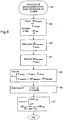
- the figure 6 illustrates the method for determining the fuel mass flow rate as performed by the device illustrated in FIG. figure 3 .
- step 52 the set value of the mass flow rate of the requested fuel or the setpoint value of the position of the requested metering device is received at the input of the hybridization device.
- the prediction module uses a model based on the variables of actual mass flow condition and parametric uncertainties for determining, from the desired value of the requested WF setpoint mass flow rate or the position of the applied X metering feeder, the estimated position of the metering doser and the estimated mass flow rate WF flowmeter at step 53.
- step 54 the mass flow rate of the fuel and the metering position are measured and inputted by the metering device. hybridization so as to calculate, in step 55, the residue vector comprising the metering residue and the flowmeter residue.
- step 56 the correction gain matrix K is determined.
- K can be calculated by a law depending on the mass flowrate of setpoint WFset, measured WFmeter or real WFreel or function of the position of the setpoint Meter Xpoint, the position of the measured metering device Xdoseur or the actual metering position Xreel. K can also be calculated from the recursive relationships A7. From this residue vector and the correction gain matrix K, the correction vector C is calculated in step 57, these corrections being applied to the real mass flow WF real and IP parametric uncertainties in step 57. The process can then start again at step 52 so as to refine the determination of the real mass flow WF real .
- variable data are recalculated and refined, for example the parametric uncertainties are refined and make it possible to determine more precisely the estimated values of the mass flow rate of the fuel and the position of the metering device. values compared to measured values as previously described.
- R metering X metering - X ⁇ metering
- R flowmeter WF flowmeter - WF ⁇ flowmeter
- E R metering
- F T + Q K not + 1 P not + 1 / not . H T H . P not + 1 / not .
Landscapes
- Engineering & Computer Science (AREA)
- Chemical & Material Sciences (AREA)
- Combustion & Propulsion (AREA)
- Mechanical Engineering (AREA)
- General Engineering & Computer Science (AREA)
- Physics & Mathematics (AREA)
- Fluid Mechanics (AREA)
- General Physics & Mathematics (AREA)
- Measuring Volume Flow (AREA)
- Combined Controls Of Internal Combustion Engines (AREA)
Claims (18)
- Vorrichtung zur Bestimmung eines Fluid-Massendurchflussmaßes für eine Verbrennungskammer umfassend einen Fluid-Dosierer und eine Messeinrichtung für die zu messende Position des Dosierers,
dadurch gekennzeichnet, dass die Vorrichtung umfasst- einen Massendurchflussmesser (14), um den zu messenden Fluid-Massendurchfluss zu messen,- eine Hybridisationsvorrichtung (16), die in der Lage ist, einen tatsächlichen Fluidmassendurchfluss zu bestimmen, und umfasst:- eine erste Eingabe, die einen Sollwert (WFconsigne) des abgefragten Massendurchflusses oder einen Sollwert (Xconsigne) der abgefragten Position des Dosierers umfasst,- ein Vorhersagemodul (26), das in der Lage ist, aus der ersten Eingabe und Zustandsvariablen, die den tatsächlichen Massendurchfluss (WFréel) und parametrische Unsicherheiten (IP) umfassen, Schätzwerte zu bestimmen, welche die geschätzte Position (^Xdoseur) des Dosierers und den geschätzten Massendurchfluss (^WFdébitmètre) umfassen,- eine zweite Eingabe, welche die gemessene Position (Xdoseur) des Dosierers und den gemessenen Fluid-Massendurchfluss (WFdébitmètre) umfasst,- einen Resteberechner (30, 22, 20), der in der Lage ist, einen ersten Rest (Rdoseur) zwischen der gemessenen Position des Dosierers und der geschätzten Position des Dosierers und einen zweiten Rest (Rdebitmetre) zwischen dem gemessenen Fluid-Massendurchfluss und dem geschätzten Fluid-Massendurchfluss zu bestimmen,- ein Korrekturmodul (24), das in der Lage ist, aus dem ersten und zweiten Rest Korrekturen zu bestimmen, die sich dazu eignen, vom Vorhersagemodul auf die Zustandsvariablen (WFréel, IP) angewendet zu werden. - Vorrichtung nach Anspruch 1, dadurch gekennzeichnet, dass das Vorhersagemodul (26) ein dynamisches Zustandsmodell umfasst, das imstande ist, die erste Eingabe mit den Zustandsvariablen und den Schätzwerten zu verknüpfen.
- Vorrichtung nach einem der Ansprüche 1 und 2, dadurch gekennzeichnet, dass das Korrekturmodul (24) eine Korrekturverstärkungsmatrix umfasst, deren Koeffizienten feststehend sind.
- Vorrichtung nach einem der Ansprüche 1 und 2, dadurch gekennzeichnet, dass das Korrekturmodul (24) eine Korrekturverstärkungsmatrix umfasst, deren Koeffizienten variabel sind.
- Vorrichtung nach Anspruch 4, dadurch gekennzeichnet, dass die Koeffizienten durch ein mathematisches Gesetz in Abhängigkeit vom Fluid-Massendurchfluss oder von der Position des Dosierers bestimmt werden.
- Vorrichtung nach Anspruch 4, dadurch gekennzeichnet, dass die Korrekturverstärkungsmatrix eine dynamisch bestimmte Verstärkungsmatrix des Kalman-Filters (K) ist.
- Vorrichtung nach Anspruch 6, dadurch gekennzeichnet, dass die Verstärkungsmatrix des Kalman-Filters (K) dynamisch durch die Verwendung von sich auf Rauschen beziehende Matrizen bestimmt wird, und einer fortgesetzten Anpassung ihrer Koeffizienten unterliegt.
- Vorrichtung nach einem der vorhergehenden Ansprüche, dadurch gekennzeichnet, dass die erste Eingabe darüber hinaus einen Messwert (Tcarburant) der Temperatur des Fluids umfasst.
- Vorrichtung nach einem der vorhergehenden Ansprüche, dadurch gekennzeichnet, dass die zweite Eingabe einen Messwert eines im Fluid-Dosierer herrschenden Druckdifferentials (^δPmesure) umfasst, wobei die Schätzwerte einen Schätzwert dieses Druckdifferentials (δPmesure) umfassen, der Resteberechner in der Lage ist, einen dritten Rest (RδP) zwischen dem Messwert und dem Schätzwert des Druckdifferentials zu bestimmen, das Korrekturmodul in der Lage ist, aus dem ersten, zweiten und dritten Rest Korrekturen zu bestimmen, die sich dazu eignen, vom Vorhersagemodul auf die Zustandsvariablen angewendet zu werden.
- Verfahren zur Bestimmung eines Fluid-Massendurchflussmaßes für eine Verbrennungskammer, die einen Fluid-Dosierer und eine Messeinrichtung für die zu messende Position des Dosierers umfasst, wobei das Verfahren dadurch gekennzeichnet ist, dass es die Schritte umfasst, die darin bestehen:a- einen Sollwert (WFconsigne) des abgefragten Massendurchflusses oder einen Sollwert (Xconsigne) der abgefragten Position des Dosierers und Zustandsvariable einzugeben, die den tatsächlichen Massendurchfluss (WFreel) und parametrische Unsicherheiten (IP) umfassen,b- aus dem Schritt a- Schätzwerte zu bestimmen, welche die geschätzte Position (^Xdoseur) des Dosierers und den geschätzten Massendurchfluss (^WFdébitmètre) umfassen,c- den Fluid-Massendurchfluss (WFdebitmetre) aus einem Massendurchfluss und der Position des Fluid-Dosierers zu messen,d- einen ersten Rest (Rdoseur) zwischen der gemessenen Position des Dosierers und der geschätzten Position (Xdoseur) des Dosierers und einen zweiten Rest (Rdebitmetre) zwischen dem gemessenen Fluid-Massendurchfluss und dem geschätzten Fluid-Massendurchfluss zu berechnen,e- aus dem ersten und zweiten Rest Korrekturen zu berechnen und Letztere auf Zustandsvariablen (Wfreel, IP) anzuwenden.
- Verfahren nach Anspruch 10, dadurch gekennzeichnet, dass der Schritt b-darin besteht, ein dynamisches Zustandsmodell zu verwenden, das imstande ist, den Sollwert mit den Zustandsvariablen und den Schätzwerten zu verknüpfen.
- Verfahren nach einem der Ansprüche 10 und 11, dadurch gekennzeichnet, dass die Berechnung des Schritts e- darin besteht, eine Korrekturverstärkungsmatrix zu verwenden, deren Koeffizienten feststehend sind.
- Verfahren nach einem der Ansprüche 10 und 11, dadurch gekennzeichnet, dass die Berechnung des Schritts e- darin besteht, eine Korrekturverstärkungsmatrix zu verwenden, deren Koeffizienten variabel sind.
- Verfahren nach Anspruch 13, dadurch gekennzeichnet, dass der Schritt e-darin besteht, die Koeffizienten durch ein mathematisches Gesetz in Abhängigkeit vom Fluid-Massendurchfluss oder von der Position des Dosierers zu bestimmen.
- Verfahren nach Anspruch 13, dadurch gekennzeichnet, dass die Korrekturverstärkungsmatrix des Schritts e- eine dynamisch bestimmte Verstärkungsmatrix des Kalman-Filters (K) ist.
- Verfahren nach Anspruch 15, dadurch gekennzeichnet, dass die Verstärkungsmatrix des Kalman-Filters des Schritts e- dynamisch durch die Verwendung von sich auf Rauschen beziehende Matrizen bestimmt wird, und einer fortgesetzten Anpassung ihrer Koeffizienten unterliegt.
- Verfahren nach einem der Ansprüche 10 bis 16, dadurch gekennzeichnet, dass der Schritt a- darüber hinaus umfasst, einen Messwert (Tcarburant) der Temperatur des Fluids einzugeben.
- Verfahren nach einem der Ansprüche 10 bis 17, dadurch gekennzeichnet, dass der Schritt b- darüber hinaus umfasst, einen Schätzwert eines im Fluid-Dosierer herrschenden Druckdifferentials (^δPmesure) zu bestimmen, der Schritt c- darüber hinaus umfasst, dieses Druckdifferential (δPmesure) zu messen, der Schritt d- darüber hinaus umfasst, einen dritten Rest (RδP) zwischen dem Messwert und dem Schätzwert des Druckdifferentials zu berechnen, der Schritt e-darüber hinaus umfasst, aus dem ersten und zweiten Rest Korrekturen zu berechnen und diese Letzteren auf die Zustandsvariablen anzuwenden.
Applications Claiming Priority (2)
| Application Number | Priority Date | Filing Date | Title |
|---|---|---|---|
| FR0310106A FR2859018B1 (fr) | 2003-08-22 | 2003-08-22 | Dispositif pour l'estimation du debit massique de carburant |
| FR0310106 | 2003-08-22 |
Publications (3)
| Publication Number | Publication Date |
|---|---|
| EP1510795A2 EP1510795A2 (de) | 2005-03-02 |
| EP1510795A3 EP1510795A3 (de) | 2006-05-24 |
| EP1510795B1 true EP1510795B1 (de) | 2017-05-31 |
Family
ID=34089849
Family Applications (1)
| Application Number | Title | Priority Date | Filing Date |
|---|---|---|---|
| EP04292044.7A Expired - Lifetime EP1510795B1 (de) | 2003-08-22 | 2004-08-12 | Vorrichtung zur Abschätzung des Massendurchflusses von Kraftstoff |
Country Status (5)
| Country | Link |
|---|---|
| US (1) | US7107169B2 (de) |
| EP (1) | EP1510795B1 (de) |
| CA (1) | CA2478793C (de) |
| FR (1) | FR2859018B1 (de) |
| RU (1) | RU2289031C2 (de) |
Families Citing this family (15)
| Publication number | Priority date | Publication date | Assignee | Title |
|---|---|---|---|---|
| US20080295568A1 (en) * | 2007-06-01 | 2008-12-04 | Gilbarco Inc. | System and method for automated calibration of a fuel flow meter in a fuel dispenser |
| FR2945075B1 (fr) * | 2009-04-29 | 2015-06-05 | Snecma | Procede et dispositif pour alimenter une chambre de turbomachine avec un debit de carburant regule |
| US9267831B2 (en) | 2010-01-29 | 2016-02-23 | General Electric Company | Systems and methods for determining a real time solid flow rate in a solid-gas mixture |
| FR2958976B1 (fr) * | 2010-04-15 | 2012-06-15 | Snecma | Procede et dispositif d'elaboration d'un signal de consigne representatif d'un debit de carburant |
| FR2966518B1 (fr) * | 2010-10-25 | 2012-11-30 | Snecma | Commande d'un dispositif de dosage de carburant pour turbomachine |
| FR2992355B1 (fr) * | 2012-06-21 | 2014-07-18 | Snecma | Procede et dispositif d'ajustement d'une valeur seuil de debit carburant |
| US20140290261A1 (en) * | 2013-03-28 | 2014-10-02 | Solar Turbines Incorporated | Compensation for gas turbine engine fuel valve characteristics |
| FR3021701B1 (fr) * | 2014-05-27 | 2016-06-17 | Snecma | Procede et dispositif de controle d'une poussee d'un turboreacteur |
| FR3021740B1 (fr) * | 2014-06-03 | 2016-06-24 | Snecma | Procede et systeme d'evaluation d'un debit d'un fluide |
| US10330023B2 (en) | 2015-02-19 | 2019-06-25 | United Technologies Corporation | Fuel flow estimation and control system and method in a gas turbine engine |
| US10975776B2 (en) * | 2016-04-07 | 2021-04-13 | Raytheon Technologies Corporation | Adaptive fuel flow estimation with flow meter feedback |
| US10900421B2 (en) * | 2018-10-17 | 2021-01-26 | Woodward, Inc. | Direct feedback regarding metered flow of fuel system |
| CN109728796B (zh) * | 2018-12-12 | 2022-11-15 | 哈尔滨理工大学 | 一种基于事件触发机制的滤波方法 |
| FR3094086B1 (fr) * | 2019-03-19 | 2021-03-19 | Safran Aircraft Engines | Procédé de surveillance de l’état de fonctionnement d’un bloc hydromécanique |
| CN116642562B (zh) * | 2023-07-27 | 2023-10-20 | 黑龙江惠达科技股份有限公司 | 一种植保无人机药液质量测量系统、方法和无人机 |
Family Cites Families (10)
| Publication number | Priority date | Publication date | Assignee | Title |
|---|---|---|---|---|
| SU805327A1 (ru) * | 1978-05-22 | 1981-02-15 | Предприятие П/Я Р-6378 | Устройство дл исследовани характеристикгАзОТуРбиННыХ дВигАТЕлЕй |
| SU924536A1 (ru) * | 1979-12-28 | 1982-04-30 | Предприятие П/Я А-3251 | Стенд дл испытани регул торов расхода турбореактивного двигател |
| GB2077434B (en) * | 1980-05-30 | 1984-04-26 | Millar John | Ascertaining flow rate through valves or pumps |
| US4593523A (en) * | 1980-12-17 | 1986-06-10 | Allied Corporation | Method and apparatus for acceleration limiting a gas turbine engine |
| GB2195448B (en) * | 1986-09-19 | 1990-07-25 | Spirax Sarco Ltd | Flowmeter calibration |
| US5274996A (en) * | 1991-10-11 | 1994-01-04 | Allied-Signal, Inc. | Closed loop fuel control system |
| US6148601A (en) * | 1998-05-08 | 2000-11-21 | Hamilton Sundstrand Corporation | Engine fuel control system and method |
| RU2178871C1 (ru) * | 2000-10-11 | 2002-01-27 | Государственный научный центр Центральный научно-исследовательский и опытно-конструкторский институт робототехники и технической кибернетики | Массовый расходомер газожидкостного потока |
| US6750261B1 (en) * | 2003-04-08 | 2004-06-15 | 3M Innovative Properties Company | High internal phase emulsion foams containing polyelectrolytes |
| US7082842B2 (en) * | 2004-06-25 | 2006-08-01 | Rivatek Incorporated | Software correction method and apparatus for a variable orifice flow meter |
-
2003
- 2003-08-22 FR FR0310106A patent/FR2859018B1/fr not_active Expired - Lifetime
-
2004
- 2004-08-05 US US10/911,521 patent/US7107169B2/en not_active Expired - Lifetime
- 2004-08-12 EP EP04292044.7A patent/EP1510795B1/de not_active Expired - Lifetime
- 2004-08-20 CA CA2478793A patent/CA2478793C/fr not_active Expired - Lifetime
- 2004-08-20 RU RU2004125542/06A patent/RU2289031C2/ru not_active IP Right Cessation
Non-Patent Citations (1)
| Title |
|---|
| None * |
Also Published As
| Publication number | Publication date |
|---|---|
| RU2004125542A (ru) | 2006-01-27 |
| US7107169B2 (en) | 2006-09-12 |
| FR2859018A1 (fr) | 2005-02-25 |
| FR2859018B1 (fr) | 2005-10-07 |
| CA2478793C (fr) | 2012-07-03 |
| EP1510795A2 (de) | 2005-03-02 |
| EP1510795A3 (de) | 2006-05-24 |
| US20050043905A1 (en) | 2005-02-24 |
| RU2289031C2 (ru) | 2006-12-10 |
| CA2478793A1 (fr) | 2005-02-22 |
Similar Documents
| Publication | Publication Date | Title |
|---|---|---|
| EP1510795B1 (de) | Vorrichtung zur Abschätzung des Massendurchflusses von Kraftstoff | |
| FR2534708A1 (fr) | Installation electronique pour la commande ou pour la regulation de grandeurs caracteristiques du fonctionnement d'un moteur a combustion interne | |
| EP1621749B1 (de) | Vorrichtung zur Bestimmung einer in einem NOx-Speicher gespeicherte NOx-Masse und ein Überwachungssystem für die Regeneration des NOx-Speichers beinhaltend eine solche Vorrichtung | |
| WO2012045939A1 (fr) | Systeme propulsif de lanceur spatial et un procede de regulation de consommation d ' ergols | |
| WO2021234257A1 (fr) | Procédé pour déterminer des caractéristiques d'un carburant alimentant un moteur d'aéronef | |
| WO2012100916A1 (fr) | Procede de determination de la teneur en alcool d'un nouveau melange de carburant dans un moteur a combustion interne d'un vehicule, et dispositif pour sa mise en oeuvre | |
| EP2619426B1 (de) | Vefahren zur adaptiven beurteilung der momentanen russlast eines partikelfiltes | |
| EP2864615A1 (de) | Verfahren und vorrichtung zur einstellung eines grenzwertes einer brennstoffflussrate | |
| EP4153852B1 (de) | Luftfahrzeug, das in seinem kraftstofftank eine kammer mit einem sensor umfasst | |
| EP2700793A1 (de) | Korrekturverfahren einer Schätzung der Rußmasse in einem Partikelfilter | |
| FR3092143A1 (fr) | Procédé de détermination d’une quantité de carburant injecté dans un moteur à combustion interne | |
| FR2777878A1 (fr) | Procede de recuperation de vapeurs emises au cours d'une distribution de liquide | |
| FR3103270A1 (fr) | Procédé et système de détermination du débit massique d’un fluide dans un circuit de fluide pour la commande d’une vanne de dosage du circuit de fluide | |
| FR2962213A1 (fr) | Systeme de dosage de debit massique pour applications d'avion | |
| EP4348025B1 (de) | Verfahren zur überwachung von adaptionswerten in einer motorsteuerung | |
| FR2886979A1 (fr) | Procede pour l'adaptation automatique du diagramme caracteristique de commande pilote d'une pompe de diesel de rampe d'injection commune a reglage de flux volumetrique | |
| FR3025590A1 (fr) | Repartition du debit en injection multipoints en fonction du rapport carburant/air dans la chambre de combustion | |
| EP3008315B1 (de) | Verfahren zur diagnose des betriebszustands von kraftstoffinjektoren in einer brennkraftmaschine, brennkraftmaschine und kraftfahrzeug zur durchführung des verfahrens | |
| EP3215727B1 (de) | Verfahren zur vorhersage einer gaseinlassseitigen drosselklappe für die steuerung einer brennkraftmaschine | |
| EP4348024B1 (de) | Verfahren zur begrenzung einer von mehreren adaptionswerten ausgeführten parameterkorrektur in einer motorsteuerung | |
| EP2786004B1 (de) | Verfahren und vorrichtung für die kontinuierliche schätzung des luft-kraftstoff-verhältnis in einem motorzylinder | |
| FR2890694A1 (fr) | Dispositif d'injection de carburants a caracteristiques variables | |
| FR3096137A1 (fr) | Recalage de modèle PS3 dans une turbomachine | |
| FR3096031A1 (fr) | Recalage de modèle par segment ou plan dans une turbomachine | |
| FR2987072A1 (fr) | Procede de correction d'un systeme de calcul de la consommation d'huile d'un moteur equipe d'un filtre a particules |
Legal Events
| Date | Code | Title | Description |
|---|---|---|---|
| PUAI | Public reference made under article 153(3) epc to a published international application that has entered the european phase |
Free format text: ORIGINAL CODE: 0009012 |
|
| AK | Designated contracting states |
Kind code of ref document: A2 Designated state(s): AT BE BG CH CY CZ DE DK EE ES FI FR GB GR HU IE IT LI LU MC NL PL PT RO SE SI SK TR |
|
| AX | Request for extension of the european patent |
Extension state: AL HR LT LV MK |
|
| 17P | Request for examination filed |
Effective date: 20050215 |
|
| RAP1 | Party data changed (applicant data changed or rights of an application transferred) |
Owner name: SNECMA |
|
| PUAL | Search report despatched |
Free format text: ORIGINAL CODE: 0009013 |
|
| AK | Designated contracting states |
Kind code of ref document: A3 Designated state(s): AT BE BG CH CY CZ DE DK EE ES FI FR GB GR HU IE IT LI LU MC NL PL PT RO SE SI SK TR |
|
| AX | Request for extension of the european patent |
Extension state: AL HR LT LV MK |
|
| RIC1 | Information provided on ipc code assigned before grant |
Ipc: F02C 9/16 20060101ALI20060404BHEP Ipc: F02C 9/28 20060101ALI20060404BHEP Ipc: F02C 9/00 20060101AFI20060404BHEP Ipc: G01F 1/86 20060101ALI20060404BHEP |
|
| AKX | Designation fees paid |
Designated state(s): DE FR GB SE |
|
| 17Q | First examination report despatched |
Effective date: 20140219 |
|
| REG | Reference to a national code |
Ref country code: DE Ref legal event code: R079 Ref document number: 602004051322 Country of ref document: DE Free format text: PREVIOUS MAIN CLASS: G01F0001860000 Ipc: F02C0009000000 |
|
| GRAP | Despatch of communication of intention to grant a patent |
Free format text: ORIGINAL CODE: EPIDOSNIGR1 |
|
| RIC1 | Information provided on ipc code assigned before grant |
Ipc: F02C 9/26 20060101ALI20170208BHEP Ipc: F02C 9/16 20060101ALI20170208BHEP Ipc: G01F 1/86 20060101ALI20170208BHEP Ipc: F02C 9/00 20060101AFI20170208BHEP Ipc: F02C 9/28 20060101ALI20170208BHEP |
|
| INTG | Intention to grant announced |
Effective date: 20170221 |
|
| GRAS | Grant fee paid |
Free format text: ORIGINAL CODE: EPIDOSNIGR3 |
|
| GRAA | (expected) grant |
Free format text: ORIGINAL CODE: 0009210 |
|
| AK | Designated contracting states |
Kind code of ref document: B1 Designated state(s): DE FR GB SE |
|
| REG | Reference to a national code |
Ref country code: GB Ref legal event code: FG4D Free format text: NOT ENGLISH |
|
| REG | Reference to a national code |
Ref country code: DE Ref legal event code: R096 Ref document number: 602004051322 Country of ref document: DE |
|
| REG | Reference to a national code |
Ref country code: FR Ref legal event code: PLFP Year of fee payment: 14 |
|
| REG | Reference to a national code |
Ref country code: SE Ref legal event code: TRGR |
|
| REG | Reference to a national code |
Ref country code: DE Ref legal event code: R097 Ref document number: 602004051322 Country of ref document: DE |
|
| PLBE | No opposition filed within time limit |
Free format text: ORIGINAL CODE: 0009261 |
|
| STAA | Information on the status of an ep patent application or granted ep patent |
Free format text: STATUS: NO OPPOSITION FILED WITHIN TIME LIMIT |
|
| 26N | No opposition filed |
Effective date: 20180301 |
|
| REG | Reference to a national code |
Ref country code: FR Ref legal event code: PLFP Year of fee payment: 15 |
|
| PGFP | Annual fee paid to national office [announced via postgrant information from national office to epo] |
Ref country code: GB Payment date: 20230720 Year of fee payment: 20 |
|
| PGFP | Annual fee paid to national office [announced via postgrant information from national office to epo] |
Ref country code: SE Payment date: 20230720 Year of fee payment: 20 Ref country code: FR Payment date: 20230720 Year of fee payment: 20 Ref country code: DE Payment date: 20230720 Year of fee payment: 20 |
|
| REG | Reference to a national code |
Ref country code: DE Ref legal event code: R071 Ref document number: 602004051322 Country of ref document: DE |
|
| REG | Reference to a national code |
Ref country code: GB Ref legal event code: PE20 Expiry date: 20240811 |
|
| REG | Reference to a national code |
Ref country code: SE Ref legal event code: EUG |
|
| PG25 | Lapsed in a contracting state [announced via postgrant information from national office to epo] |
Ref country code: GB Free format text: LAPSE BECAUSE OF EXPIRATION OF PROTECTION Effective date: 20240811 |
|
| PG25 | Lapsed in a contracting state [announced via postgrant information from national office to epo] |
Ref country code: GB Free format text: LAPSE BECAUSE OF EXPIRATION OF PROTECTION Effective date: 20240811 |