EP1512882B1 - Cylindre hydraulique - Google Patents
Cylindre hydraulique Download PDFInfo
- Publication number
- EP1512882B1 EP1512882B1 EP04018885A EP04018885A EP1512882B1 EP 1512882 B1 EP1512882 B1 EP 1512882B1 EP 04018885 A EP04018885 A EP 04018885A EP 04018885 A EP04018885 A EP 04018885A EP 1512882 B1 EP1512882 B1 EP 1512882B1
- Authority
- EP
- European Patent Office
- Prior art keywords
- piston rod
- fixing element
- hydraulic cylinder
- cylinder
- piston
- Prior art date
- Legal status (The legal status is an assumption and is not a legal conclusion. Google has not performed a legal analysis and makes no representation as to the accuracy of the status listed.)
- Expired - Lifetime
Links
- 239000004033 plastic Substances 0.000 claims description 12
- 230000002093 peripheral effect Effects 0.000 claims description 9
- 230000000295 complement effect Effects 0.000 claims description 5
- 230000000630 rising effect Effects 0.000 claims description 5
- 238000002347 injection Methods 0.000 claims description 3
- 239000007924 injection Substances 0.000 claims description 3
- 239000000463 material Substances 0.000 claims description 2
- 238000007789 sealing Methods 0.000 description 10
- 239000000428 dust Substances 0.000 description 6
- 238000001746 injection moulding Methods 0.000 description 5
- 238000004519 manufacturing process Methods 0.000 description 4
- 239000000853 adhesive Substances 0.000 description 3
- 230000001070 adhesive effect Effects 0.000 description 3
- 239000012530 fluid Substances 0.000 description 3
- 230000005540 biological transmission Effects 0.000 description 2
- 230000015572 biosynthetic process Effects 0.000 description 2
- 230000006835 compression Effects 0.000 description 2
- 238000007906 compression Methods 0.000 description 2
- 238000006073 displacement reaction Methods 0.000 description 2
- 238000005516 engineering process Methods 0.000 description 2
- 239000000243 solution Substances 0.000 description 2
- 238000013459 approach Methods 0.000 description 1
- 230000001419 dependent effect Effects 0.000 description 1
- 230000000881 depressing effect Effects 0.000 description 1
- 238000013461 design Methods 0.000 description 1
- 238000011161 development Methods 0.000 description 1
- 230000018109 developmental process Effects 0.000 description 1
- 229920001971 elastomer Polymers 0.000 description 1
- 239000000806 elastomer Substances 0.000 description 1
- 230000002349 favourable effect Effects 0.000 description 1
- 238000003780 insertion Methods 0.000 description 1
- 230000037431 insertion Effects 0.000 description 1
- 238000009434 installation Methods 0.000 description 1
- 239000007788 liquid Substances 0.000 description 1
- 238000000034 method Methods 0.000 description 1
- 239000002991 molded plastic Substances 0.000 description 1
- 230000001681 protective effect Effects 0.000 description 1
Images



Classifications
-
- F—MECHANICAL ENGINEERING; LIGHTING; HEATING; WEAPONS; BLASTING
- F16—ENGINEERING ELEMENTS AND UNITS; GENERAL MEASURES FOR PRODUCING AND MAINTAINING EFFECTIVE FUNCTIONING OF MACHINES OR INSTALLATIONS; THERMAL INSULATION IN GENERAL
- F16D—COUPLINGS FOR TRANSMITTING ROTATION; CLUTCHES; BRAKES
- F16D25/00—Fluid-actuated clutches
- F16D25/08—Fluid-actuated clutches with fluid-actuated member not rotating with a clutching member
- F16D25/088—Fluid-actuated clutches with fluid-actuated member not rotating with a clutching member the line of action of the fluid-actuated members being distinctly separate from the axis of rotation
Definitions
- the invention relates to a hydraulic cylinder according to the preamble of claim 1.
- the invention relates to a slave cylinder for a hydraulic clutch actuation for motor vehicles, as they are used in masses in the automotive industry.
- a conventional hydraulic clutch actuator for motor vehicles has a master cylinder connected to a reservoir filled with hydraulic fluid.
- the master cylinder has a cylinder housing, in the housing bore a piston is received longitudinally displaceable.
- the master cylinder piston bounded in the housing bore of the cylinder housing a pressure chamber and can be mechanically acted upon by means of a clutch pedal or an electric motor drive with an actuating force.
- the pressure chamber of the master cylinder is hydraulically connected via a pressure line to a pressure chamber of a slave cylinder, so that the pressure generated by depressing the clutch pedal or electromotive displacement of the master cylinder piston in the pressure chamber of the master cylinder via the liquid column in the pressure line to the pressure chamber of the slave cylinder is transferable.
- the slave cylinder also has a cylinder housing with a housing bore in which a pressure chamber of the slave cylinder limiting and thus acted upon by the pressure generated in the master cylinder piston is taken longitudinally displaceable.
- the slave cylinder piston is associated with a piston rod which engages a clutch lever, which in turn is in operative connection with the release bearing of the clutch.
- a slave cylinder having a housing bore having a housing housing, a longitudinally displaceably received in the housing bore piston and a piston rod associated with the piston, wherein slave cylinder, a fixing is provided, which is connected before a first operation of the slave cylinder releasably connected to the piston rod and this with respect to the cylinder housing in one predetermined stroke, ie fixed axial position and which is further adapted to release the piston rod relative to the cylinder housing with the first actuation of the slave cylinder.
- the fixing element has an annular flange portion, which is inserted into a stepped end portion of the housing bore of the cylinder housing at its open end and fixed there by means of a securing ring.
- a plurality of thin fastening strips extend in the radial direction inwardly to the end remote from the piston of the piston rod, where they merge integrally into the piston rod head to the piston rod with respect to the cylinder housing to tie before a first operation of the slave cylinder in a predetermined stroke position.
- the invention is based on the object to provide a hydraulic cylinder as simple as possible, especially slave cylinder for a hydraulic clutch actuation for motor vehicles, in which the piston rod is tied to the cylinder housing before the first actuation of the hydraulic cylinder in a predetermined stroke position and first operation the hydraulic cylinder is released, without this being associated with the problems described above in discussion of the prior art.
- a hydraulic cylinder in particular slave cylinder for a hydraulic clutch actuation for motor vehicles
- a hydraulic cylinder in particular slave cylinder for a hydraulic clutch actuation for motor vehicles
- a housing bore a cylinder housing, a longitudinally displaceably received in the housing bore piston, a piston associated with the piston rod and a fixing element
- the detachable before a first actuation of the hydraulic cylinder with the Piston rod is connected and this fixed relative to the cylinder housing in a predetermined stroke position and which is adapted to release the piston rod relative to the cylinder housing with the first actuation of the hydraulic cylinder
- Other purposes of the invention include avoiding overfilling of a hydraulic cylinder according to the invention having the hydraulic system in its pre-filling, wherein the fixing ensures that the hydraulic cylinder can absorb only a predetermined amount of hydraulic fluid before its first operation, and securing the hydraulic cylinder according to the invention against transport damage, wherein the fixing element during transport of the hydraulic cylinder prevents excessive protrusion of the piston rod out of the cylinder housing.
- the middle region of the piston rod with which the fixing element is releasably connected prior to the first actuation of the hydraulic cylinder is understood to be the region of the piston rod which lies between the end regions of the piston rod via which the piston rod engages with the piston or piston rod .
- the clutch lever in the case of a clutch slave cylinder is operatively connected, so the area of the piston rod, which does not count to the end regions, wherein the releasable connection between the fixing and piston rod according to the respective requirements in the middle center or nearer to the one or the other end of the Piston rod can lie.
- the fixing element for fixing and positioning the Piston rod opposite the cylinder housing is in a first position before the first actuation of the hydraulic cylinder and is displaced with the first actuation of the hydraulic cylinder from this first position to a second, different from the first position position range, where the fixing element is set for further actuations of the hydraulic cylinder , so it remains.
- the fixing element may be formed integrally with the piston rod in the further pursuit of the inventive concept.
- Such integral formation of fixing element and piston rod may e.g. be achieved in manufacturing technology particularly simple manner by injection molding of plastic.
- the fixing element may also be a separate part from the piston rod.
- the latter embodiment has u.a. the advantage that modular solutions are possible in which the same trained fixing in different hydraulic cylinders with different pistons and / or piston rods can be used.
- the fixing element may be annular and surround the piston rod. With suitable dimensioning of the fixing in the radial direction, it is thus possible, in addition to the temporary binding of the piston rod in a predetermined stroke position, the piston rod before the first operation the hydraulic cylinder to fix in a predetermined angular position with respect to the central axis of the housing bore in the cylinder housing to facilitate the assembly of the hydraulic cylinder at the site.
- the detachable with the first actuation of the hydraulic cylinder connection between the fixing element and the piston rod can be carried out in various ways.
- the releasable connection between the fixing element and the piston rod can in particular be made in a materially bonded manner via at least one predetermined breaking point between the fixing element and the piston rod or a support holding the fixing element in the first position on the piston rod.
- This predetermined breaking point (s) breaks / break with the first actuation of the hydraulic cylinder, so that the piston rod, if necessary, comes free from the fixing element together with the carrier for the fixing element.
- the fixing element has an outer ring and a plurality of from the outer ring to radially inwardly extending connecting webs, in each case via a predetermined breaking point in one piece with the piston rod or provided within the outer ring support ring before the first actuation of the hydraulic cylinder are connected as a carrier, which is arranged in the first position on a seat on the piston rod.
- the support ring may be arranged concentrically within the outer ring.
- the fixing element holds the piston rod in a substantially aligned position with the center axis of the housing bore in the cylinder housing before the first actuation of the hydraulic cylinder, which facilitates the assembly of the hydraulic cylinder at the place of use, because the piston rod are not aligned by hand must, for example in the case of a clutch slave cylinder, the end facing away from the piston of the piston rod be able to thread into a recess associated with this on the clutch lever.
- the support ring is arranged with an axial and possibly angular offset to the outer ring of the fixing within the outer ring to the piston rod with respect to the central axis of the housing bore in the cylinder housing in front of the first actuation of the hydraulic cylinder to keep a predetermined angle. It may be expedient if the support ring is arranged rotationally fixed relative to the piston rod on the seat on the piston rod.
- predetermined breaking points an adhesive bond with a defined adhesive force between the connecting webs and the piston rod or the supporting ring would, in principle, be conceivable.
- the predetermined breaking points are each formed cohesively by a cross-sectional taper of the respective connecting web between the outer ring and the piston rod or the support ring.
- the detachable connection between the fixing and the piston rod in particular the respective material requirements according to also form-fitting manner by means of complementary interlocking structures on the fixing element and the piston rod be made with a resilient Formation of fixing and / or piston rod such that upon application of a force acting in the axial direction of the piston rod and exceeds a predetermined force, the structures come under a radial evasive movement of fixing and / or piston rod disengaged.
- the piston rod be provided in its central region with a radial groove having a semicircular cross section and engages in the form of a complementary shaped annular portion of the fixing before the first actuation of the hydraulic cylinder, wherein the fixing member has a longitudinally continuous slot to aufspredern radially outward ,
- the piston rod also remain unchanged except for the additional radial groove in its central region compared with proven conventional piston rods in an advantageous manner.
- the fixing element abuts in its first position on an abutment surface, which is formed on a penetrated by the piston rod, the open end of the housing bore on an annular collar of the cylinder housing or an insert mounted there.
- the second, piston rod fixed position range for the fixing between its first position on the piston rod and the piston is close to the piston, advantageously results in a particularly large angular mobility of the piston rod in the housing bore of the cylinder housing without the angular movement of the piston rod is obstructed by the fixing element fixed in its second position.
- a structure may be formed in the second, piston rod or cylinder housing-fixed position range for the fixing element, with the aid of which a structure, which may be complementarily shaped, on the fixing element, can form-fit engageable to set the fixing member for further operations of the hydraulic cylinder.
- a positive fixing of the fixing in the second, piston rod or cylinder housing fixed position range can be - compared with about one also conceivable Druckverklebung - implement constructively with advantageously little effort.
- a plurality of locking lugs may be provided with which from an outer ring of the fixing radially inward extending connecting webs of the fixing element can be latched, which are resiliently formed for this purpose in the axial direction of the fixing.
- Such locking lugs can be formed in a simple manner when the piston rod is injection molded from plastic.
- connecting webs of the fixing element could in principle also be provided with a continuous longitudinal slot in the outer ring or have a mesh or lattice-like shape to a radial springing of the fixing and thus locking the To allow connecting webs of the fixing with the locking lugs on the piston rod.
- the piston rod may be provided in the second, piston rod fixed position range for the fixing with a circumferential radial groove into which the fixing element is snapped, including the fixing is provided with a continuous longitudinal slot in the longitudinal direction, while the piston rod has at least one to the second, piston rod fixed position range rising slope, by means of which the fixing element during the first actuation of the hydraulic cylinder for producing the snap connection is radially auffederbar.
- the fixing element may, in principle, have a mesh or lattice-like shape instead of the slot in order to allow a radial springing of the fixing element, which however is less preferred because it requires a higher production outlay.
- the arrangement for a form-fitting fixing of the fixing element to the cylinder housing that accompanies the first actuation of the hydraulic cylinder can advantageously be made such as that the cylinder housing is provided with an undercut on an open end of the housing bore or an insert part mounted thereon in the second, cylinder housing fixed position range for the fixing element, into which a locking lug formed on the fixing element can be snapped, wherein the fixing element in turn engages with a in whose longitudinal direction is provided by continuous slot, while the cylinder housing side is provided for a second, cylinder housing fixed position range rising joining edge, via which the fixing element at the first Actuation of the hydraulic cylinder for producing the snap connection is radially auffederbar.
- the fixing can serve as a stop element in its second, piston rod or cylinder housing fixed position, which cooperates with a cylinder housing or piston rod fixed counter-stop to limit the stroke of the piston in the housing bore of the cylinder housing, so that the fixing advantageously fulfills another function.
- the fixing element is made of plastic, in particular injection molded from it.
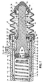
- a slave cylinder 10 for a hydraulic clutch actuation for motor vehicles is now shown as an example of a hydraulic cylinder, which has a metallic cylinder housing 12 in the illustrated embodiment, in which starting from a front side designed as a blind bore housing bore 14 is introduced.
- a plastic piston 16 is longitudinally displaceably received, which is associated with a piston rod 18.
- the slave cylinder 10 further includes a fixing member 20 which is releasably connected to the piston rod 18 prior to a first operation of the slave cylinder 10 and fixes them with respect to the cylinder housing 12 in a predetermined stroke position, and which is adapted to with the first actuation of the slave cylinder 10, the piston rod 18 with respect to the cylinder housing 12 release. It is essential that the fixing element 20 - as shown in Fig.
- piston rod fixed (or alternatively: cylinder housing fixed) position range 24 is displaceable, in which the fixing element 20 can be fixed for further operations of the slave cylinder 10 to remain there, as will also be explained in detail.
- the cylinder housing 12 is provided on the outer peripheral side with a mounting flange 26 for mounting the slave cylinder 10 in the motor vehicle having two mounting holes 28 through which in the assembled state of the slave cylinder 10, for example screws (not shown) extend through, the attachment the slave cylinder 10 at about a transmission wall (not shown) serve in the vehicle.
- open end of the cylinder housing 12 is further provided with an annular recess 30 which serves to center and fasten a likewise made of plastic in the illustrated embodiment, annular securing element 32 through which the piston rod 18 extends therethrough and which inter alia prevents the piston 16 can be pulled out of the housing bore 14.
- annular recess 30 the slotted, a substantially L-shaped cross-section having fuse element 32 by means of an outer peripheral side mounted on its longer leg, circumferential nose 34 and fixed compression, which undercut at an opening provided in the annular recess 30 recess 36th engages behind.
- the cylinder housing 12 further has in the region of its in Fig.
- a biasing spring 56 is received in the form of a helical compression spring, which is supported with its one, in Fig. 1 left end on the bottom wall 48 of the cylinder housing 12, while their second, in Fig. 1 right end to a on the piston 16 fastened centering element 58 for the sealing element 50, more precisely a spring plate portion 60 of the injection-molded plastic centering element 58 rests. It can be seen that the biasing spring 56 thus exerts on the piston 16 a biasing force which tends to move the piston 16 in Fig. 1 to the right.
- the piston 16 is a piston which can be tilted in the housing bore 14 and is injection-molded from plastic, as in principle made of plastic DE 43 31 241 A1 the applicant is known.
- This piston 16 has an end face open to the pressure chamber 54, ie undercut trained, annular axial groove 62, in which the sealing element 50 is received.
- the sealing element 50 is held by an outgoing from the spring plate portion 60 of the centering 58, annular centering 64 of the centering 58, which in turn via a radially within the centering 64 to the spring plate portion 60 subsequent, hollow cylindrical mounting portion 66 in a cylindrical portion of a frontally formed in the piston 16, central recess 68 in a suitable manner, for example by means of adhesive, is attached.
- the one to the piston rod 18 conically or spherically sloping outer surface 70 having piston 16 is formed in the illustrated embodiment by injection molding of plastic integral with the piston rod 18, whose end remote from the piston 16 is formed as a ball head 72.
- the ball head 72 of the piston rod 18 engages positively in a Kugelkalottenabêt 74 a known per se, with respect to the piston rod 18 pivotable dust cap 76, via which the piston rod 18 in the vehicle-mounted state of the slave cylinder 10 operatively on a clutch lever (not shown) engages.
- the dust cap 76 has a radial groove 78 having mounting portion 80 for the bellows 42.
- the surrounding the piston rod 18 bellows 42 finally has at both longitudinal ends in each case a radially inwardly projecting collar 82, 84, of which one, in Fig. 1st left collar 82 engages in the formed on the mounting portion 40 of the cylinder housing 12 radial groove 38, while the other, in Fig. 1 right collar 84 engages in the mounting portion 80 of the dust cap 76 formed radial groove 78 to the bellows 42 both on the cylinder housing 12 and to attach to the piston rod 18.
- the piston rod 18 in the illustrated Embodiment shows the piston 16, the piston rod 18 and the fixing element 20 forming component without the sealing element 50 and the centering element 58.
- the piston rod 18 in the illustrated Embodiment inter alia, to save weight with sufficient buckling strength over its main length a substantially cross-shaped cross-section, with a uniform diameter over its length core 86 and four evenly spaced winkelbabstandet on the outer periphery of the core 86 profile webs 88 whose outer surface 90, starting from a to the ball head 72nd subsequent cylinder portion 92 of the piston rod 18 initially parallel to the central axis of the piston rod 18 extends before it increases along with a cross-sectional enlargement of the profile webs 88 via a slope 94 to the piston 16 out.
- annular fixing member 20 has an outer ring 98 with a rectangular cross-section and a plurality of, here four evenly spaced apart from the outer ring 98th radially inwardly extending connecting webs 100, which are connected before the first actuation of the slave cylinder 10 in each case via a line-like executed predetermined breaking point 102 with the piston rod 18, more precisely with the seat portions 96.
- the predetermined breaking points 102 between the connecting webs 100 of the fixing element 20 and the seat sections 96 on the piston rod 18 are each formed by a cross-sectional tapering of the respective connecting web 100.
- Each connecting web 100 of the fixing element 20 tapers in a plan view substantially V-shaped from the outer ring 98 of the fixing member 20 to the core 86 of the piston rod 18, as can be seen in particular Figs. 2 and 5, so that in the relationship narrow predetermined breaking points 102, while each connecting web 100 at the same time seen in a side view tapers substantially wedge-shaped from the outer ring 98 of the fixing member 20 to the core 86 of the piston rod 18, so that there are also thin predetermined breaking points 102 in proportion.
- the wedge-shaped taper of the connecting webs 100 can be seen in FIGS. 1, 3 and 6. As a result of the described cross-sectional tapering of the connecting webs 100, they are also able to cushion a certain amount in the axial direction of the fixing element 20 or the piston rod 18 when a predetermined force is applied.
- Figs. 1 to 4 and 6 show, is the second, piston rod fixed position portion 24 for the fixing member 20, in which the fixing member 20 is displaced with the first operation of the slave cylinder 10, between the first position of the fixing member 20 at the Piston rod 18 and the piston 16 near the piston 16.
- this second, rod-fixed position portion 24 for the fixing member 20 a structure or a profile is formed, with which a structure or a profile on the fixing member 20 can be positively engaged in order to fix the fixing element 20 for further actuations of the slave cylinder 10 in the second piston rod fixed position area 24.
- a plurality of detents 104 are provided in the second, rod-fixed position portion 24 for the fixing member 20, which are formed during injection molding of the piston 16, piston rod 18 and fixing member 20 with the same element and with which from the outer ring 98 of the fixing element 20th radially inwardly extending, resilient in the axial direction of the piston rod 18 connecting webs 100 of the fixing element 20 with the first actuation of the slave cylinder 10 are latched.
- 1 to 4 and 6 can also be seen that each six (Fig. 1) and five (Fig.
- locking lugs 104 seen in the longitudinal direction of the piston rod 18 seen one behind the other and in the circumferential direction of the piston rod 18 between in each case two adjacent profile webs 88 are formed near the core 86 of the piston rod 18 on the piston rod 18.
- the piston rod 18 is moved by the fixing member 20 both in a predetermined stroke, i. Axial position held in the cylinder housing 12 and in a predetermined angular position with respect to the central axis of the housing bore 14 in the cylinder housing 12th
- the spring-biased clutch lever (not shown) operatively connected to the ball head 72 of the piston rod 18 displaces the piston 16 back against the force of the biasing spring 56 via the piston rod 18 Bottom wall 48 of the cylinder housing 12, ie To the left in Fig. 1.
- the piston rod 18 takes the now in the second piston rod fixed position portion 24 for the fixing member 20 form-locking between adjacent in the longitudinal direction of the piston rod 18 locking lugs 104 held on the connecting webs 100 fixing 20, so that this from the fuse element 32 in Fig. 1 moved away to the left.
- this positive connection can also be superimposed by a frictional connection, for example by the diameter of the core 86 being selected to be slightly larger than the radial distance between the predetermined breaking points 102 of the fixing element 20 with respect to the center axis of the piston rod 18 , so that the connecting webs 100 resiliently press against the piston rod 18 in their locking position between locking lugs 104 which are adjacent in the longitudinal direction of the piston rod 18.
- the fixing element 20 always remains in the second piston rod fixed position portion 24 for the fixing member 20 near the piston 16 after the first actuation of the slave cylinder 10, so there is fixed captive so that it u.a. a tilting movement of the piston rod 18 with respect to the central axis of the housing bore 14 in the cylinder housing 12, which in practice e.g. +/- 5 °, not handicapped.
- Operation and function of the slave cylinder 10 in a hydraulic clutch actuation are sufficiently known, moreover, so that further explanations are dispensable for this purpose at this point.
- FIGS. 7 to 12 second embodiment will be described below only insofar as it differs from the first embodiment described with reference to FIGS. 1 to 6 and it seems necessary for the understanding of the second embodiment.
- the same or the components of the first embodiment corresponding components of the second embodiment are in this case provided with the same reference numerals as the components of the first embodiment.
- the cylinder housing 12 is formed in the second embodiment of the slave cylinder 10 of FIG. 7 in several parts, with a step bore 112 having, consisting of plastic housing base 114 and a metallic bushing 116 inserted therein with the cylindrical portion 46 as Tread for the attached to the piston 16 sealing element 50.
- a step bore 112 having, consisting of plastic housing base 114 and a metallic bushing 116 inserted therein with the cylindrical portion 46 as Tread for the attached to the piston 16 sealing element 50.
- the housing body 114 and the bushing 116 latter is provided on the outer peripheral side to both longitudinal ends, each with a radial groove 118 into which an O-ring 120 is inserted, the sealing on the inner peripheral surface the stepped bore 112 rests in the housing base body 114.
- the piston rod 18 of the slave cylinder 10 according to the second embodiment differs from the piston rod 18 of the slave cylinder 10 according to the first embodiment in FIG essential in that both the seat portions 96 and the detents 104 of the first embodiment are missing. Instead, the piston rod 18 in the second embodiment with two seats in the form of introduced into the profile webs 88, circumferential radial grooves 128, 130 provided, seen in the longitudinal direction of the piston rod 18 have a distance from each other, which corresponds at least to the disengagement of the dry friction clutch, at the the slave cylinder 10 is to be used.
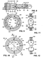
- the radially in the central region 22 of the piston rod 18 slightly eccentrically to the piston 16 arranged radial groove 128 serves the positive fixing of a support ring 132 which carries the fixing member 126 before the first actuation of the slave cylinder 10 in its first position, as shown in particular in FIG.
- the radial groove 130 formed close to the piston 16, in the second piston rod-fixed position region 24 for the fixing element 126, the groove base of which has a larger diameter than the groove base of the radial groove 128 serves, as indicated in FIG. 7 by dashed lines, the positive fixing of the fixing element 126, when the slave cylinder 10 is operated for the first time.
- the fixing element 126 is a separate part from the piston rod 18, which part is formed in one piece with the support ring 132 by injection molding of plastic.
- the fixing element 126 itself has an outer ring 136 provided with a continuous longitudinal slot 134, which has a substantially T-shaped cross section.
- On the outer ring 136 close to the inner peripheral side a plurality of, in the illustrated embodiment, four with respect to the central axis of the outer ring 136 uniformly angularly spaced, radially inwardly extending knob-like connecting webs 138, via which the fixing element 126 is detachably connected to the support ring 132.
- the connecting webs 138 taper toward the support ring 132 such that they each only have a relatively small cross-section are connected to the support ring 132, which serves as a predetermined breaking point 140.
- the detachable connection between the piston rod 18 and the fixing element 126 in its first position is produced cohesively via predetermined breaking points 140 in this embodiment, which are, however, provided here between the fixing element 126 and the support ring 132.
- the support ring 132 concentrically disposed within the outer ring 136 is crowned toward both longitudinal ends with a central annular portion 142 and projections 144 respectively extending laterally therefrom.
- the number (four) and location (even angularly spaced with respect to the central axis of the support ring 132) and the dimensions of the projections 144 are chosen such that they are capable of fixing the support ring 132 rotatably on the piston rod 18, wherein the support ring 132 only engages with its annular portion 142 in the radial groove 128 on the piston rod 18 while the projections 144 are respectively received in the circumferential direction of the piston rod 18 adjacent profile webs 88 of the piston rod 18, as Fig. 8 illustrates.
- 11 and 12 are further strip-shaped, extending in the longitudinal direction of the support ring 132 extending profiles 146, seen in the circumferential direction formed between the projections 144 on the inner circumference of the ring portion 142 to the assembly of the fixing member 126 and the Support ring 132 forming component to allow the piston rod 18.
- the component forming the fixing element 126 and its supporting ring 132 is symmetrically shaped with respect to an imaginary plane perpendicular to its central axis, so that this component can be mounted non-directionally on the piston rod 18.
- the fixing element 126 If pressure then builds up in the pressure chamber 54 during the first actuation of the slave cylinder 10, the fixing element 126 is pressed against the annular collar 122 with a higher force. If this force exceeds a structurally predetermined force, the connecting webs 138 of the fixing element 126 shear off at the predetermined breaking points 140 from the support ring 132 and the piston rod 18 is released from the fixing element 126.
- the fixing element 126 serves in its second, piston rod fixed position as a stop element, which cooperates with the abutment surface 124 of the annular collar 122 as a cylinder housing fixed counter-stop, so that the stroke of the piston 16 in the housing bore 14 of the cylinder housing 12 is limited.
- FIGS. 13 to 17 will be described below only insofar as it differs from the exemplary embodiments described with reference to FIGS. 1 to 12 and it appears necessary for the understanding of the third embodiment.
- the same or the components of the preceding embodiments corresponding components of the third embodiment are in this case provided with the same reference numerals as the components of the preceding embodiments.
- the longitudinal ends of the slave cylinder 10 have not been shown after they may be formed as shown in FIGS. 1 and 7, respectively.
- the releasable connection between a the same purpose as the fixing elements 20, 126 serving fixing element 148 and the piston rod 18 is positively produced by means of complementary interlocking structures on the fixing element 148 and the piston rod 18 ,
- the fixing element 148 is resilient, so that upon application of a force acting in the axial direction of the piston rod 18 and exceeds a predetermined force, the structures under a radial evasive movement of the fixing member 148 are disengaged.
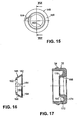
- the piston rod 18 is provided in its central region 22 with a radial groove 150 which has a semicircular cross-section and into which a complementary shaped annular portion 152 of the fixing element 148 engages in a form-fitting manner prior to the first actuation of the slave cylinder 10.
- the fixing element 148 has an oblique slot 154 running through in the longitudinal direction of the fixing element 148 in order to be able to spring radially outward.
- the second position portion 156 for the fixing member 148 in contrast to the previous embodiments cylinder housing fixed and located on the penetrated by the piston rod 18, the open end of the housing bore 14 in the cylinder housing 12, more precisely there as below Referring to FIG. 1 described secured fuse element 32nd
- a conical jacket section 158 adjoins the annular section 152 of the fixing element 148 with an inner peripheral side bevel 160, which increases towards the second cylinder housing-fixed position region 156 in accordance with FIG.
- the jacket section 158 terminates at a fastening section 162 of the fixing element 148, which is provided on the inner peripheral side with a circumferential latching lug 164 for fixing the fixing element 148 in the second, cylinder housing-fixed position region 156.
- a securing element 32 having a substantially U-shaped cross-section has an inner ring section 166 protruding into the housing bore 14 of the cylinder housing 12.
- the piston rod 18 by means of the fixing member 148, the ring portion 152 positively engages the radial groove 150 on the piston rod 18, tied in a predetermined stroke position with respect to the cylinder housing 12.
- the fixing element 148 is pressed with its fastening portion 162, more precisely its end face remote from the piston 16 as a result of the biasing force exerted by the biasing spring 56 on the piston 16 against the abutment surface 170 on the securing element 32.
- the piston rod 18 is held via the fixing element 148, whose detent lug 164 bears against the centering surface 168 of the securing element 32, in a position aligned with the center axis of the housing bore 14 of the cylinder housing 12.
- the piston 16 is also acted upon hydraulically with a force which tends to move the piston 16 in Fig. 13 to the right.
- the annular portion 152 of the slotted fixing member 148 slightly moves out of the radial groove 150 in the piston rod 18 under a radial expansion thereof.
- the detent lug 164 of the fixing element 148 jumps from the centering surface 168 of the securing element 32 onto its joining bevel 172.
- the piston rod 18 can move relative to the cylinder housing 12 and takes the fixing member 148 to the right in Fig. 13 with.
- the slotted fixing element 148 is continuously expanded under engagement of the locking lug 164 on the joining bevel 172 of the securing element 32 until the locking lug 164 of the fixing element 148 engages with the undercut 174 on the securing element 32 or snaps into it.
- the fixing element 148 is now form-fitting on Secured fuse element 32 so that the piston rod 18 is unlocked and freely movable in the axial direction. This condition is shown in FIG.
- piston rod 18 is formed integrally with the piston 16 throughout, it will be apparent to those skilled in the art that the above-described releasable captivation of the piston rod 18 relative to the cylinder housing 12 by means of the fixing member 20, 126 and 148, of course, also for piston rods Can use, which engage loosely in an associated recess in the piston or positively, for example by means of a ball joint connected to the piston.
- the slave cylinder 10 described above can be used both in pre-filled as well as in non-pre-filled hydraulic clutch actuations, in particular simplifying the assembly of the slave cylinder 10 in the motor vehicle in particular insofar as doing so as a result of the piston rod 18 relative to the cylinder housing 12 in constructive predetermined position captivating fixing member 20, 126 or 148 on the one hand, the piston rod 18 does not have to be moved against the force of the biasing spring 56 of the slave cylinder 10 in the axial direction in the cylinder housing 12 and on the other hand, the piston rod 18 in a fixed angular position with respect to the central axis of Housing bore 14 is held, so that the piston rod 18 does not have to be cumbersome manually aligned here. Even after the first actuation of the slave cylinder 10, the fixing element 20, 126 or 148 remains an integral part of the slave cylinder 10, which leaves the piston 16 remote from the actuating end of the piston rod 18 always untouched.
- a hydraulic cylinder comprising a cylinder housing having a housing bore, one in the housing bore longitudinally displaceably received piston, a piston associated with the piston rod and a fixing member which is releasably connected to the piston rod before a Zylindererstbet Oberist and fixed with respect to the cylinder housing in a predetermined stroke position and which is adapted to release the piston rod relative to the cylinder housing with the Zylindererstbetruc neglect.
- the fixing element is releasably connected in a first position with a central region of the piston rod before Zylindererstbettechnik institute and displaceable with the Zylindererstbet2011 concerns of the first position in a second, especially piston rod fixed position range in which it can be fixed for further cylinder actuations.
- a simply designed hydraulic cylinder is provided in which the fixing element provided for the temporary binding of the piston rod in particular leaves the end of the piston rod remote from the piston untouched and does not hinder the operation of the hydraulic cylinder any further.
Landscapes
- Engineering & Computer Science (AREA)
- General Engineering & Computer Science (AREA)
- Mechanical Engineering (AREA)
- Actuator (AREA)
- Hydraulic Clutches, Magnetic Clutches, Fluid Clutches, And Fluid Joints (AREA)
Claims (19)
- Vérin ou cylindre hydraulique (10), notamment vérin ou cylindre récepteur pour un actionnement hydraulique d'embrayage de véhicule automobile, comprenant un carter de vérin (12) qui présente un alésage de carter (14), un piston (16) reçu en coulissement longitudinal dans l'alésage de carter (14), une tige de piston (18) associée au piston (16), et un élément de fixation (20, 126, 148) qui, avant un premier actionnement du vérin hydraulique (10) est relié de manière amovible à la tige de piston (18) et fixe celle-ci dans une position de course prédéterminée par rapport au carter de vérin (12), et est réalisé de façon à libérer la tige de piston (18) par rapport au carter de vérin (12) avec le premier actionnement du vérin hydraulique (10), caractérisé en ce que l'élément de fixation (20, 126, 148), avant le premier actionnement du vérin hydraulique (10), est relié de manière amovible, dans une première position, à une zone centrale (22) de la tige de piston (18), et peut, avec le premier actionnement du vérin hydraulique (10), être déplacé de la première position dans une deuxième zone de position (24, 156) fixe avec la tige de piston ou avec le carter de vérin, dans laquelle il peut être immobilisé et fixé pour d'autres actionnements suivants du vérin hydraulique (10).
- Vérin hydraulique (10) selon la revendication 1, caractérisé en ce que l'élément de fixation (20) est réalisé d'un seul tenant avec la tige de piston (18).
- Vérin hydraulique (10) selon la revendication 1, caractérisé en ce que l'élément de fixation (126, 148) est une pièce séparée de la tige de piston (18).
- Vérin hydraulique (10) selon l'une des revendications précédentes, caractérisé en ce que l'élément de fixation (20, 126, 148) est de forme annulaire et entoure la tige de piston (18).
- Vérin hydraulique (10) selon la revendication 1, caractérisé en ce que la liaison amovible entre l'élément de fixation (20, 126) et la tige de piston (18) est établie notamment par continuité de matière, par l'intermédiaire d'au moins une zone de rupture programmée (102, 140) entre l'élément de fixation (20, 126) et la tige de piston (18), ou un support (132) qui maintient l'élément de fixation (126) dans la première position sur la tige de piston (18).
- Vérin hydraulique (10) selon la revendication 5, caractérisé en ce que l'élément de fixation (20, 126) comprend un anneau extérieur (98, 136) et plusieurs nervures de liaison (100, 138) qui s'étendent radialement vers l'intérieur à partir de l'anneau extérieur (98, 136), et qui avant le premier actionnement du vérin hydraulique (10), sont reliées, respectivement par l'intermédiaire d'une zone de rupture programmée (102, 140), d'un seul tenant avec la tige de piston (18) ou avec un anneau de support (132) en tant que support, qui est prévu à l'intérieur de l'anneau extérieur (136) et est disposé, dans la première position, sur une portée (128) de la tige de piston (18).
- Vérin hydraulique (10) selon la revendication 6, caractérisé en ce que l'anneau de support (132) est agencé concentriquement à l'intérieur de l'anneau extérieur (136).
- Vérin hydraulique (10) selon la revendication 6 ou 7, caractérisé en ce que les zones de rupture programmée (102, 140) sont respectivement formées par un rétrécissement de section transversale de la nervure de liaison respective (100, 138) entre l'anneau extérieur (98, 136) et la tige de piston (18) ou l'anneau de support (132) en tant que support.
- Vérin hydraulique (10) selon la revendication 1, caractérisé en ce que la liaison amovible entre l'élément de fixation (148) et la tige de piston (18) est établie par complémentarité de formes au moyen de structures (150, 152) sur l'élément de fixation (148) et la tige de piston (18), qui s'engagent de manière complémentaire les unes dans les autres, l'élément de fixation (148) et/ou la tige de piston (18) étant de configuration élastique de façon telle que lors de l'application d'une force, qui agit dans la direction de l'axe de la tige de piston (18) et dépasse une force prédéterminée, les structures (150, 152) se mettent hors de prise réciproque sous l'effet d'un mouvement d'esquive radiale de l'élément de fixation (148) et/ou de la tige de piston (18).
- Vérin hydraulique (10) selon la revendication 9, caractérisé en ce que la tige de piston (18) est pourvue dans sa zone centrale (22), d'une rainure radiale (150) qui présente une section transversale demi-ronde et dans laquelle s'engage par complémentarité de formes, avant le premier actionnement du vérin hydraulique (10), un tronçon d'anneau (152) de forme complémentaire de l'élément de fixation (148), l'élément de fixation (148) possédant une fente (154) continue dans la direction longitudinale, en vue de pouvoir s'ouvrir radialement vers l'extérieur de manière élastique.
- Vérin hydraulique (10) selon l'une des revendications précédentes, caractérisé en ce que l'élément de fixation (20, 126, 148), dans sa première position, s'appuie sur une surface de butée (106, 124, 170) qui est formée au niveau d'une extrémité ouverte de l'alésage de carter (14), traversée par la tige de piston (18), sur un collet ou épaulement annulaire (122) du carter de vérin (12) ou sur une pièce d'insert (32) rapportée à cet endroit.
- Vérin hydraulique (10) selon la revendication 1, caractérisé en ce que la deuxième zone de position (24) fixe avec la tige de piston, pour l'élément de fixation (20, 126), se trouve entre la première position de ce dernier sur la tige de piston (18) et le piston (16), à proximité du piston (16).
- Vérin hydraulique (10) selon la revendication 1, caractérisé en ce que la deuxième zone de position (156) fixe avec le carter de vérin, pour l'élément de fixation (148), se trouve au niveau d'une extrémité ouverte de l'alésage de carter (14) dans le carter de vérin (12), traversée par la tige de piston (18).
- Vérin hydraulique (10) selon la revendication 1, caractérisé en ce que dans la deuxième zone de position (24, 156), fixe avec la tige de piston ou avec le carter de vérin, pour l'élément de fixation (20, 126, 148), est formée une structure (104, 130, 174) avec laquelle peut être amenée en prise par complémentarité de formes, une structure (100, 136, 164), le cas échéant de forme complémentaire, sur l'élément de fixation (20, 126, 148), pour immobiliser et fixer l'élément de fixation (20, 126, 148) pour les actionnements suivants du vérin hydraulique (10).
- Vérin hydraulique (10) selon la revendication 14, caractérisé en ce que dans la deuxième zone de position (24) fixe avec la tige de piston, pour l'élément de fixation (20), sont prévus plusieurs talons d'encliquetage (104) avec lesquels peuvent venir s'encliqueter des nervures de liaison (100) de l'élément de fixation (20), qui s'étendent radialement vers l'intérieur en étant issues d'un anneau extérieur (98) de l'élément de fixation (20), et sont à cet effet, d'une configuration élastique dans la direction axiale de l'élément de fixation (20).
- Vérin hydraulique (10) selon la revendication 14, caractérisé en ce que la tige de piston (18) est pourvue, dans la deuxième zone de position (24) fixe avec la tige de piston, pour l'élément de fixation (126), d'une rainure radiale (130) périphérique, dans laquelle peut s'enclencher l'élément de fixation (126), ce pour quoi l'élément de fixation (126) est pourvu d'une fente (134) continue dans la direction longitudinale de l'élément de fixation, tandis que la tige de piston (18) présente au moins une rampe (94) qui est montante en direction de la deuxième zone de position (24) fixe avec la tige de piston, et au moyen de laquelle l'élément de fixation (126) peut, lors du premier actionnement du vérin hydraulique (10), être évasé radialement, de manière élastique, pour établir la liaison par enclenchement.
- Vérin hydraulique (10) selon la revendication 14, caractérisé en ce que le carter de vérin (12) est pourvu, au niveau d'une extrémité ouverte de l'alésage de carter (14), traversée par la tige de piston (18), ou d'une pièce d'insert (32) rapportée à cet endroit, dans la deuxième zone de position (156) fixe avec le carter de vérin, pour l'élément de fixation (148), d'une contre-dépouille (174) dans laquelle peut venir s'enclencher un talon d'encliquetage (164) réalisé sur l'élément de fixation (148), l'élément de fixation (148) étant pourvu d'une fente (154) continue dans la direction longitudinale de l'élément de fixation, tandis que, côté carter de vérin, est prévue une rampe d'assemblage (172) qui est montante en direction de la deuxième zone de position (156) fixe avec le carter de vérin, et par l'intermédiaire de laquelle l'élément de fixation (148) peut, lors du premier actionnement du vérin hydraulique (10), être évasé radialement, de manière élastique, pour établir la liaison par enclenchement.
- Vérin hydraulique (10) selon l'une des revendications précédentes, caractérisé en ce que l'élément de fixation (20, 126, 148), dans sa deuxième position fixe avec la tige de piston ou avec le carter de vérin, sert d'élément de butée qui interagit avec une butée conjuguée (106, 170) fixe avec le carter de vérin ou respectivement la tige de piston, pour limiter la course du piston (16) dans l'alésage de carter (14) du carter de vérin (12).
- Vérin hydraulique (10) selon l'une des revendications précédentes, caractérisé en ce que l'élément de fixation (20, 126, 148) est réalisé en matière plastique, notamment moulé par injection de cette matière plastique.
Applications Claiming Priority (2)
| Application Number | Priority Date | Filing Date | Title |
|---|---|---|---|
| DE10341470A DE10341470A1 (de) | 2003-09-05 | 2003-09-05 | Hydraulikzylinder |
| DE10341470 | 2003-09-05 |
Publications (3)
| Publication Number | Publication Date |
|---|---|
| EP1512882A2 EP1512882A2 (fr) | 2005-03-09 |
| EP1512882A3 EP1512882A3 (fr) | 2006-08-16 |
| EP1512882B1 true EP1512882B1 (fr) | 2007-10-24 |
Family
ID=34129706
Family Applications (1)
| Application Number | Title | Priority Date | Filing Date |
|---|---|---|---|
| EP04018885A Expired - Lifetime EP1512882B1 (fr) | 2003-09-05 | 2004-08-10 | Cylindre hydraulique |
Country Status (4)
| Country | Link |
|---|---|
| US (1) | US7216752B2 (fr) |
| EP (1) | EP1512882B1 (fr) |
| DE (2) | DE10341470A1 (fr) |
| ES (1) | ES2295742T3 (fr) |
Cited By (1)
| Publication number | Priority date | Publication date | Assignee | Title |
|---|---|---|---|---|
| DE102014222945A1 (de) | 2013-12-04 | 2015-06-11 | Schaeffler Technologies AG & Co. KG | Faltenbalg mit Entlüftung |
Families Citing this family (19)
| Publication number | Priority date | Publication date | Assignee | Title |
|---|---|---|---|---|
| DE102004058609A1 (de) * | 2004-12-03 | 2006-06-08 | Fte Automotive Gmbh | Hydraulikzylinder, insbesondere Nehmerzylinder für eine hydraulische Kupplungsbetätigung für Kraftfahrzeuge |
| DE102007034978A1 (de) * | 2007-07-26 | 2009-01-29 | Wabco Gmbh | Pneumatikkomponente |
| DE102008058704A1 (de) | 2007-12-17 | 2009-06-25 | Luk Lamellen Und Kupplungsbau Beteiligungs Kg | Hydraulikzylinder |
| DE102008057651A1 (de) | 2007-12-17 | 2009-06-18 | Luk Lamellen Und Kupplungsbau Beteiligungs Kg | Hydraulikzylinder |
| DE102009001779A1 (de) * | 2009-03-24 | 2010-09-30 | Zf Friedrichshafen Ag | Druckmittelantrieb mit einer Schutzhülle |
| DE102009026766A1 (de) * | 2009-06-05 | 2010-12-16 | Zf Friedrichshafen Ag | Druckmittelzylinder für eine Betätigungseinrichtung eines Kraftfahrzeuges mit einem arretierbaren Kolben |
| DE102011102301A1 (de) | 2010-05-31 | 2011-12-01 | Schaeffler Technologies Gmbh & Co. Kg | Hydraulikzylinder |
| DE102011081654A1 (de) * | 2011-08-26 | 2013-02-28 | Schaeffler Technologies AG & Co. KG | Anordnung zur kolbenstangenseitigen Abdichtung eines Geberzylinders |
| DE102011081900A1 (de) * | 2011-08-31 | 2013-02-28 | Schaeffler Technologies AG & Co. KG | Haltevorrichtung für Kolbenstange |
| DE112013005600A5 (de) * | 2012-11-22 | 2015-10-22 | Schaeffler Technologies AG & Co. KG | Kolben-Zylinder-Einheit |
| KR101847594B1 (ko) * | 2013-12-03 | 2018-05-24 | 주식회사 만도 | 쇽업소버 |
| DE102014215518A1 (de) * | 2014-08-06 | 2016-02-11 | Schaeffler Technologies AG & Co. KG | Geberzylinder mit Führungshülse für Dichtlippe des Schnüffelsystems |
| DE102015010055A1 (de) * | 2015-08-07 | 2017-02-09 | Fte Automotive Gmbh | Hydraulikzylinder, insbesondere Nehmerzylinder für eine hydraulische Kupplungsbetätigung für Kraftfahrzeuge |
| DE102015010054A1 (de) | 2015-08-07 | 2017-02-09 | Fte Automotive Gmbh | Hydraulikzylinder, insbesondere Nehmerzylinder für eine hydraulische Kupplungsbetätigung für Kraftfahrzeuge |
| CN105387020A (zh) * | 2015-12-28 | 2016-03-09 | 湖州环丰机械有限公司 | 上变幅油缸的缸体机构 |
| DE112017000878A5 (de) * | 2016-02-18 | 2018-10-25 | Schaeffler Technologies AG & Co. KG | Kupplungsgeberzylinder |
| DE102017011793B3 (de) | 2017-12-20 | 2019-05-16 | Fte Automotive Gmbh | Hydraulikzylinder mit einer belüfteten Schutzeinrichtung an einer Kolbenstange |
| CN114278644B (zh) * | 2022-01-05 | 2023-11-28 | 三一汽车制造有限公司 | 自锁油缸及作业机械 |
| DE102022105641A1 (de) * | 2022-03-10 | 2023-09-14 | Schaeffler Technologies AG & Co. KG | Haltevorrichtung zur Positionssicherung einer Ringdichtung an einem Kolbenelement einer Nehmervorrichtung |
Family Cites Families (12)
| Publication number | Priority date | Publication date | Assignee | Title |
|---|---|---|---|---|
| US4557361A (en) * | 1982-02-01 | 1985-12-10 | Automotive Products Plc | Shipping and installation strap for linear actuator |
| US4454632A (en) * | 1982-02-01 | 1984-06-19 | Automotive Products Plc | Shipping and installation strap for linear actuator |
| US4581979A (en) * | 1983-07-01 | 1986-04-15 | Automotive Products Plc | Shipping and installation restraining clip for master cylinder input member |
| US4665802A (en) * | 1985-03-07 | 1987-05-19 | Automotive Products Plc | Shipping and installation restraining strap for slave cylinder |
| US4766804A (en) * | 1987-02-24 | 1988-08-30 | Automotive Products Plc | Retainer assembly for hydraulic actuator |
| US5002169A (en) * | 1989-08-07 | 1991-03-26 | Automotive Products Plc | Restraining strap |
| FR2651841B1 (fr) * | 1989-09-13 | 1994-09-30 | Automotive Prod France | Cylindre hydraulique recepteur notamment pour embrayage de vehicule automobile. |
| DE4331241B4 (de) * | 1993-09-15 | 2004-02-05 | Fte Automotive Gmbh | Hydraulischer Betätigungszylinder |
| DE19516392C5 (de) * | 1995-05-04 | 2004-04-29 | Zf Sachs Ag | Druckmittelantrieb |
| JP4107788B2 (ja) * | 2000-01-31 | 2008-06-25 | 日信工業株式会社 | 車両用アクチュエータの保持構造 |
| DE10038012A1 (de) * | 2000-08-04 | 2002-02-21 | Porsche Ag | Vorrichtung zur Befestigung einer hydraulischen Kupplungsbetätigungseinrichtung, insbesondere Kupplungsnehmerzylinder |
| JP3739321B2 (ja) * | 2002-01-18 | 2006-01-25 | 日信工業株式会社 | 車両用アクチュエータの保持構造 |
-
2003
- 2003-09-05 DE DE10341470A patent/DE10341470A1/de not_active Withdrawn
-
2004
- 2004-08-10 ES ES04018885T patent/ES2295742T3/es not_active Expired - Lifetime
- 2004-08-10 DE DE502004005314T patent/DE502004005314D1/de not_active Expired - Lifetime
- 2004-08-10 EP EP04018885A patent/EP1512882B1/fr not_active Expired - Lifetime
- 2004-09-03 US US10/934,148 patent/US7216752B2/en not_active Expired - Fee Related
Non-Patent Citations (1)
| Title |
|---|
| None * |
Cited By (1)
| Publication number | Priority date | Publication date | Assignee | Title |
|---|---|---|---|---|
| DE102014222945A1 (de) | 2013-12-04 | 2015-06-11 | Schaeffler Technologies AG & Co. KG | Faltenbalg mit Entlüftung |
Also Published As
| Publication number | Publication date |
|---|---|
| DE10341470A1 (de) | 2005-04-07 |
| EP1512882A3 (fr) | 2006-08-16 |
| ES2295742T3 (es) | 2008-04-16 |
| EP1512882A2 (fr) | 2005-03-09 |
| US20050051407A1 (en) | 2005-03-10 |
| US7216752B2 (en) | 2007-05-15 |
| DE502004005314D1 (de) | 2007-12-06 |
Similar Documents
| Publication | Publication Date | Title |
|---|---|---|
| EP1512882B1 (fr) | Cylindre hydraulique | |
| EP1789670B1 (fr) | Couvercle de culasse pour culasse de moteur a combustion interne | |
| EP2561245B1 (fr) | Capuchon de butée | |
| DE3222711C2 (de) | Ausrücklager | |
| DE10302707B4 (de) | Anordnung zur abstandsvariabien Verbindung eines Montageteils mit einer Unterkonstruktion | |
| EP1454071A1 (fr) | Ecrou de raccordement concu pour visser des elements de construction sur un composant de type plaque | |
| DE202008010262U1 (de) | Verbindungsbaugruppe zur Befestigung eines Anbauelements auf einem Trägerelement | |
| DE69601057T2 (de) | Hydraulisch betätigtes ausrücklager für kraftfahrzeugkupplung mit membranfeder | |
| DE10106915A1 (de) | Federungsanordnung | |
| EP1369597A2 (fr) | Vérin hydraulique | |
| WO2012155884A1 (fr) | Dispositif de débrayage à actionnement hydraulique, comportant un carter composé de plusieurs pièces | |
| DE3990401C2 (de) | Ausrückmechanismus für eine Kupplung | |
| EP1666752B1 (fr) | Cylindre hydraulique, en particulier cylindre récepteur pour actionnement hydraulique d'embrayage de véhicules | |
| WO2018001554A1 (fr) | Cylindre émetteur, en particulier pour un dispositif hydraulique d'actionnement d'embrayage dans des véhicules | |
| EP3128198B1 (fr) | Verin hydraulique, en particulier cylindre recepteur pour une commande d'embrayage hydraulique de vehicule automobile | |
| WO1997001469A1 (fr) | Elements d'etancheite loges dans un maitre-cylindre | |
| DE69716573T2 (de) | Hydraulischer verbinder für hydraulische kupplungsbetätigung | |
| EP2053252B1 (fr) | Dispositif hydraulique destiné à la commande d'au moins un composant de véhicule | |
| EP2737220B1 (fr) | Dispositif de liaison pour relier temporairement deux pièces de préférence en forme de plaque ainsi qu'aiguille pour un tel dispositif de liaison | |
| DE102004013662B4 (de) | Hauptbremszylinder mit integrierter Transportsicherung | |
| EP1085228B1 (fr) | Dispositif de débrayage pour actionneur d'embrayage hydraulique | |
| EP2878844B1 (fr) | Frein à disque | |
| EP1464862B1 (fr) | Dispositif central de débrayage pour un embrayage hydraulique | |
| DE102007043560A1 (de) | Fahrzeuglenkrad | |
| DE4338262C2 (de) | Hydraulisch betätigbares Ausrücksystem für eine gezogene Reibungskupplung |
Legal Events
| Date | Code | Title | Description |
|---|---|---|---|
| PUAI | Public reference made under article 153(3) epc to a published international application that has entered the european phase |
Free format text: ORIGINAL CODE: 0009012 |
|
| AK | Designated contracting states |
Kind code of ref document: A2 Designated state(s): AT BE BG CH CY CZ DE DK EE ES FI FR GB GR HU IE IT LI LU MC NL PL PT RO SE SI SK TR |
|
| AX | Request for extension of the european patent |
Extension state: AL HR LT LV MK |
|
| RAP1 | Party data changed (applicant data changed or rights of an application transferred) |
Owner name: FTE AUTOMOTIVE GMBH |
|
| PUAL | Search report despatched |
Free format text: ORIGINAL CODE: 0009013 |
|
| AK | Designated contracting states |
Kind code of ref document: A3 Designated state(s): AT BE BG CH CY CZ DE DK EE ES FI FR GB GR HU IE IT LI LU MC NL PL PT RO SE SI SK TR |
|
| AX | Request for extension of the european patent |
Extension state: AL HR LT LV MK |
|
| 17P | Request for examination filed |
Effective date: 20060805 |
|
| GRAP | Despatch of communication of intention to grant a patent |
Free format text: ORIGINAL CODE: EPIDOSNIGR1 |
|
| GRAS | Grant fee paid |
Free format text: ORIGINAL CODE: EPIDOSNIGR3 |
|
| AKX | Designation fees paid |
Designated state(s): DE ES FR GB IT |
|
| GRAA | (expected) grant |
Free format text: ORIGINAL CODE: 0009210 |
|
| AK | Designated contracting states |
Kind code of ref document: B1 Designated state(s): DE ES FR GB IT |
|
| REG | Reference to a national code |
Ref country code: GB Ref legal event code: FG4D Free format text: NOT ENGLISH |
|
| REF | Corresponds to: |
Ref document number: 502004005314 Country of ref document: DE Date of ref document: 20071206 Kind code of ref document: P |
|
| GBT | Gb: translation of ep patent filed (gb section 77(6)(a)/1977) |
Effective date: 20080123 |
|
| REG | Reference to a national code |
Ref country code: ES Ref legal event code: FG2A Ref document number: 2295742 Country of ref document: ES Kind code of ref document: T3 |
|
| ET | Fr: translation filed | ||
| PLBE | No opposition filed within time limit |
Free format text: ORIGINAL CODE: 0009261 |
|
| STAA | Information on the status of an ep patent application or granted ep patent |
Free format text: STATUS: NO OPPOSITION FILED WITHIN TIME LIMIT |
|
| 26N | No opposition filed |
Effective date: 20080725 |
|
| REG | Reference to a national code |
Ref country code: FR Ref legal event code: PLFP Year of fee payment: 13 |
|
| REG | Reference to a national code |
Ref country code: FR Ref legal event code: PLFP Year of fee payment: 14 |
|
| PGFP | Annual fee paid to national office [announced via postgrant information from national office to epo] |
Ref country code: GB Payment date: 20170929 Year of fee payment: 14 Ref country code: ES Payment date: 20170901 Year of fee payment: 14 Ref country code: IT Payment date: 20170726 Year of fee payment: 14 |
|
| REG | Reference to a national code |
Ref country code: FR Ref legal event code: PLFP Year of fee payment: 15 |
|
| GBPC | Gb: european patent ceased through non-payment of renewal fee |
Effective date: 20180810 |
|
| PG25 | Lapsed in a contracting state [announced via postgrant information from national office to epo] |
Ref country code: IT Free format text: LAPSE BECAUSE OF NON-PAYMENT OF DUE FEES Effective date: 20180810 |
|
| REG | Reference to a national code |
Ref country code: ES Ref legal event code: FD2A Effective date: 20190918 |
|
| PG25 | Lapsed in a contracting state [announced via postgrant information from national office to epo] |
Ref country code: ES Free format text: LAPSE BECAUSE OF NON-PAYMENT OF DUE FEES Effective date: 20180811 Ref country code: GB Free format text: LAPSE BECAUSE OF NON-PAYMENT OF DUE FEES Effective date: 20180810 |
|
| PGFP | Annual fee paid to national office [announced via postgrant information from national office to epo] |
Ref country code: DE Payment date: 20200806 Year of fee payment: 17 Ref country code: FR Payment date: 20200831 Year of fee payment: 17 |
|
| REG | Reference to a national code |
Ref country code: DE Ref legal event code: R119 Ref document number: 502004005314 Country of ref document: DE |
|
| PG25 | Lapsed in a contracting state [announced via postgrant information from national office to epo] |
Ref country code: FR Free format text: LAPSE BECAUSE OF NON-PAYMENT OF DUE FEES Effective date: 20210831 Ref country code: DE Free format text: LAPSE BECAUSE OF NON-PAYMENT OF DUE FEES Effective date: 20220301 |