EP1512892A1 - Dosierventil - Google Patents
Dosierventil Download PDFInfo
- Publication number
- EP1512892A1 EP1512892A1 EP04020985A EP04020985A EP1512892A1 EP 1512892 A1 EP1512892 A1 EP 1512892A1 EP 04020985 A EP04020985 A EP 04020985A EP 04020985 A EP04020985 A EP 04020985A EP 1512892 A1 EP1512892 A1 EP 1512892A1
- Authority
- EP
- European Patent Office
- Prior art keywords
- valve
- longitudinal axis
- sectional area
- cross
- poppet
- Prior art date
- Legal status (The legal status is an assumption and is not a legal conclusion. Google has not performed a legal analysis and makes no representation as to the accuracy of the status listed.)
- Withdrawn
Links
- 238000011084 recovery Methods 0.000 claims abstract description 16
- 238000004891 communication Methods 0.000 claims abstract description 6
- 230000000295 complement effect Effects 0.000 claims description 14
- 239000012530 fluid Substances 0.000 claims description 13
- 238000002485 combustion reaction Methods 0.000 claims description 12
- 230000013011 mating Effects 0.000 claims description 6
- 239000007789 gas Substances 0.000 description 15
- 239000000446 fuel Substances 0.000 description 10
- 230000008901 benefit Effects 0.000 description 6
- 238000013461 design Methods 0.000 description 6
- 239000000463 material Substances 0.000 description 4
- 238000000034 method Methods 0.000 description 4
- 238000012856 packing Methods 0.000 description 4
- 238000012360 testing method Methods 0.000 description 4
- 238000007789 sealing Methods 0.000 description 3
- 238000000926 separation method Methods 0.000 description 3
- 230000008602 contraction Effects 0.000 description 2
- 230000003247 decreasing effect Effects 0.000 description 2
- 238000001595 flow curve Methods 0.000 description 2
- VNWKTOKETHGBQD-UHFFFAOYSA-N methane Chemical compound C VNWKTOKETHGBQD-UHFFFAOYSA-N 0.000 description 2
- 238000012986 modification Methods 0.000 description 2
- 230000004048 modification Effects 0.000 description 2
- 230000007704 transition Effects 0.000 description 2
- 238000005094 computer simulation Methods 0.000 description 1
- 239000003344 environmental pollutant Substances 0.000 description 1
- 238000002347 injection Methods 0.000 description 1
- 239000007924 injection Substances 0.000 description 1
- 239000007788 liquid Substances 0.000 description 1
- 230000007246 mechanism Effects 0.000 description 1
- 239000003345 natural gas Substances 0.000 description 1
- 238000004806 packaging method and process Methods 0.000 description 1
- 231100000719 pollutant Toxicity 0.000 description 1
- 238000001556 precipitation Methods 0.000 description 1
- 230000006798 recombination Effects 0.000 description 1
- 238000005215 recombination Methods 0.000 description 1
- 230000004044 response Effects 0.000 description 1
- 229910001220 stainless steel Inorganic materials 0.000 description 1
- 239000010935 stainless steel Substances 0.000 description 1
- 238000011144 upstream manufacturing Methods 0.000 description 1
Images






Classifications
-
- F—MECHANICAL ENGINEERING; LIGHTING; HEATING; WEAPONS; BLASTING
- F16—ENGINEERING ELEMENTS AND UNITS; GENERAL MEASURES FOR PRODUCING AND MAINTAINING EFFECTIVE FUNCTIONING OF MACHINES OR INSTALLATIONS; THERMAL INSULATION IN GENERAL
- F16K—VALVES; TAPS; COCKS; ACTUATING-FLOATS; DEVICES FOR VENTING OR AERATING
- F16K1/00—Lift valves or globe valves, i.e. cut-off apparatus with closure members having at least a component of their opening and closing motion perpendicular to the closing faces
- F16K1/32—Details
- F16K1/34—Cutting-off parts, e.g. valve members, seats
- F16K1/36—Valve members
- F16K1/38—Valve members of conical shape
- F16K1/385—Valve members of conical shape contacting in the closed position, over a substantial axial length, a seat surface having the same inclination
-
- F—MECHANICAL ENGINEERING; LIGHTING; HEATING; WEAPONS; BLASTING
- F16—ENGINEERING ELEMENTS AND UNITS; GENERAL MEASURES FOR PRODUCING AND MAINTAINING EFFECTIVE FUNCTIONING OF MACHINES OR INSTALLATIONS; THERMAL INSULATION IN GENERAL
- F16K—VALVES; TAPS; COCKS; ACTUATING-FLOATS; DEVICES FOR VENTING OR AERATING
- F16K1/00—Lift valves or globe valves, i.e. cut-off apparatus with closure members having at least a component of their opening and closing motion perpendicular to the closing faces
- F16K1/32—Details
- F16K1/34—Cutting-off parts, e.g. valve members, seats
- F16K1/36—Valve members
- F16K1/38—Valve members of conical shape
-
- F—MECHANICAL ENGINEERING; LIGHTING; HEATING; WEAPONS; BLASTING
- F16—ENGINEERING ELEMENTS AND UNITS; GENERAL MEASURES FOR PRODUCING AND MAINTAINING EFFECTIVE FUNCTIONING OF MACHINES OR INSTALLATIONS; THERMAL INSULATION IN GENERAL
- F16K—VALVES; TAPS; COCKS; ACTUATING-FLOATS; DEVICES FOR VENTING OR AERATING
- F16K1/00—Lift valves or globe valves, i.e. cut-off apparatus with closure members having at least a component of their opening and closing motion perpendicular to the closing faces
- F16K1/32—Details
- F16K1/52—Means for additional adjustment of the rate of flow
-
- F—MECHANICAL ENGINEERING; LIGHTING; HEATING; WEAPONS; BLASTING
- F16—ENGINEERING ELEMENTS AND UNITS; GENERAL MEASURES FOR PRODUCING AND MAINTAINING EFFECTIVE FUNCTIONING OF MACHINES OR INSTALLATIONS; THERMAL INSULATION IN GENERAL
- F16K—VALVES; TAPS; COCKS; ACTUATING-FLOATS; DEVICES FOR VENTING OR AERATING
- F16K1/00—Lift valves or globe valves, i.e. cut-off apparatus with closure members having at least a component of their opening and closing motion perpendicular to the closing faces
- F16K1/32—Details
- F16K1/54—Arrangements for modifying the way in which the rate of flow varies during the actuation of the valve
Definitions
- the present invention relates to control valves and, in particular, to metering valves.
- Fluid valves are well known mechanisms that are used to control the flow of a fluid (e.g., gas or liquid) through a conduit.
- a metering valve is a type of valve that provides precise control of the amount of fluid flowing through a conduit. Metering valves are used in a wide variety of industrial applications in which precise control is desired.
- metering valves are used to control the amount of fuel (e.g., natural gas) that is delivered to the combustion chamber of a gas turbine.
- fuel e.g., natural gas
- the operating pressure of the combustion chamber may be limited by the available supply pressure of the fuel supplied to the combustion chamber.
- the supply pressure may be increased by replacing and/or adding additional compressors to raise the supply pressure.
- the supply pressure can be increased by reducing the pressure loss through the metering valve. Such pressure loss is often referred to as pressure recovery and is determined by the ratio of the total pressure at the inlet of the valve over the total pressure measured at the outlet of the valve.
- angle metering valve One type of metering valve is an angle metering valve.
- Such angle valves have an inlet and an outlet that have longitudinal axes that are not parallel to each other. The angle between the longitudinal axes are often determined by the position of existing conduits and/or space limitations. Ninety degrees is a common angle in angle valves. Turning the direction of the fluid through an angle valve typically results in decreased pressure recovery.
- a valve includes a valve body that comprises an inlet passage that forms an inlet port, an outlet passage that forms an outlet port, and a plenum.
- An internal valve trim has an inner surface that defines an internal passage for connecting the plenum to the outlet port.
- the inner surface includes a first surface that defines a valve seat and an opening having an average diameter.
- a valve poppet is moveably positioned at least partially within the internal passage.
- the valve poppet includes an outer surface that includes a complementary surface for mating with the valve seat and substantially closing the internal passage when the valve is in a closed position.
- the outer surface of the valve poppet further includes a distal portion located downstream of the complementary surface.
- the distal portion tapers from a first section having a first cross-sectional area to a second section having a second cross-sectional area.
- the second cross-sectional area being less than 25% of the first cross-sectional area and the second section being located a distance that is at least twice the average diameter of the opening downstream of the first section.
- a valve in another embodiment, comprises a valve body that includes an inlet passage that forms an inlet port, an outlet passage that forms an outlet port, and a plenum in fluid communication with the inlet and outlet port.
- the inlet port defines a first longitudinal axis and the outlet port defines a second longitudinal axis.
- the inlet port has a cross-sectional area and the plenum has a maximum cross-sectional area in a plane perpendicular to the first longitudinal axis that is at least 10 times greater than the cross-sectional area of the inlet port.
- An internal valve trim defines an inner surface that defines an internal passage for connecting the plenum to the outlet port.
- the inner surface includes a first surface that defines a valve seat.
- a valve poppet is moveably positioned at least partially within the internal passage.
- the valve poppet includes an outer surface that includes a complementary surface for mating with the valve seat and substantially closing the internal passage when the valve is in a closed position.
- the outer surface of the valve poppet further includes a distal portion located downstream of the complementary surface and having a generally tapered shape.
- a power system comprises a gas turbine having an combustion chamber and a gas supply system for supplying gas to the gas turbine.
- the gas supply system includes at least one metering valve.
- the metering valve comprises a valve body that includes an inlet passage that forms an inlet port, an outlet passage that forms an outlet port, and a plenum in fluid communication with the inlet and outlet port.
- the inlet port defines a first longitudinal axis and the outlet port defines a second longitudinal axis.
- the first and second longitudinal axes are orientated about ninety degrees with respect to each other.
- An internal valve trim defines an inner surface that defines an internal passage for connecting the plenum to the outlet port.
- the inner surface includes a first surface that defines a valve seat.
- a valve poppet is moveably positioned at least partially within the internal passage.
- the valve poppet including an outer surface that includes a complementary surface for mating with the valve seat and substantially closing the internal passage when the valve is in a closed position.
- the outer surface of the valve poppet further includes a distal portion located downstream of the complementary surface and having a generally tapered shape.
- the valve is configured to provide a pressure recovery of 1.06 over a majority of the valve poppet stroke.
- a valve in another embodiment, comprises a valve body that includes an inlet passage that forms an inlet port, an outlet passage that forms an outlet port, and a plenum in fluid communication with the inlet and outlet port.
- the inlet port defines a first longitudinal axis and the outlet port defines a second longitudinal axis that is orientated about ninety degrees with respect to the first longitudinal axis.
- An internal valve trim defines an inner surface that defines an internal passage for connecting the plenum to the outlet port.
- the inner surface includes a first surface that defines a valve seat and a second surface for defining a diffuser.
- the second surface is curved along a longitudinal axis of the internal passage and is concave with respect to the longitudinal axis of the internal passage.
- a valve poppet is moveably positioned at least partially within the internal passage.
- the valve poppet includes an outer surface that includes a complementary surface for mating with the valve seat and substantially closing the internal passage when the valve is in a closed position.
- the outer surface of the valve poppet further includes a distal portion located downstream of the complementary surface and has a generally tapered shape.
- Figure 1 is a side view of an exemplary embodiment of a control valve.
- Figure 2 is a cross-sectional side view of the control valve of Figure 1, which shows a valve poppet and an internal valve trim.
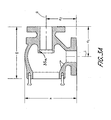
- Figure 3A is a cross-sectional side view of the control valve of Figure 1 without the valve poppet and the internal valve trim.
- Figure 3B is a cross-sectional view taken through line 3B-3B of Figure 1 without the valve poppet and the internal valve trim.
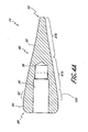
- Figure 4A is a cross-sectional side view of the valve poppet of Figure 2 .
- Figure 4B is a side view of an example modified embodiment of a valve poppet.
- Figure 4C is a side view of another example modified embodiment of a valve poppet.
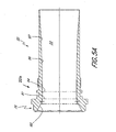
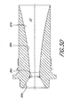
- Figure 5A is a cross-sectional side view of the example internal valve trim of Figure 2.
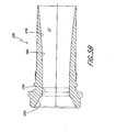
- Figure 5B is a cross-sectional side view of an example modified embodiment of an internal valve trim.
- Figure 5C is a cross-sectional side view of another example modified embodiment of an internal valve trim.
- Figure 5D is a cross-sectional side view of another example modified embodiment of an internal valve trim.
- Figure 6 is a graphical illustration of the flow of fluid through the example valve of Figure 1 as a function of the stroke of the valve poppet.
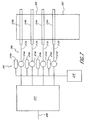
- Figure 7 is a side view of an exemplary power system.
- One embodiment of the present invention provides a high recovery metering valve with a novel physical configuration. As will be described below, one embodiment reduces flow separation from diffuser walls, prevents or reduces flow interruptions by use of appropriate radii, minimizes or reduces abrupt contraction and expansion losses, has a high ratio of a plenum cross-sectional area to an inlet port cross-sectional area, and provides a relatively large inlet radii.
- One example embodiment advantageously, provide a pressure recovery of about 1.06 over a majority of a poppet stroke.
- Figure 1 is a side view of an exemplary embodiment of a valve 10.
- Figure 2 is a cross-sectional side view of the valve 10.
- the valve 10 may be used as a metering valve in a variety of industrial and commercial applications.
- the valve 10 may be used as a metering valve for controlling the amount of fuel supplied to a gas turbine.
- An advantage of the exemplary embodiment is that the valve 10 provides improved pressure recovery.
- the valve 10 comprises a valve body 12 in which a valve poppet 14 is moveably positioned to control the amount of fluid flowing through the valve 10.
- the valve body 12 comprises an inlet passage 16, which forms an inlet port 18, and an outlet passage 20, which forms an outlet port 22.
- the valve 10 is right angle valve. That is, longitudinal axes i, o extending through the inlet and outlet ports 18, 22 are generally perpendicular to each other. This arrangement between the inlet and outlet ports 18, 22 allows the valve 10 to fit within many conventional design envelops in which it is required that the inlet and outlet ports 18, 22 be perpendicular to each other. However, it should be appreciated that in other embodiments, the longitudinal axes i, o of the inlet and outlets ports 18, 22 may be oriented at different angles with respect to each other to fit within different design envelopes.
- the body 10 includes an inlet flange 24 and an outlet flange 26, which surround the inlet and outlet ports 18, 22 respectively.
- the flanges 24, 26 may be formed in any of a variety of conventional or other arrangements to facilitate a secure connection between the valve 10 and a corresponding inlet and/or outlet conduit (not shown).
- the flanges 24, 26 are manufactured per ANSI B16.5 and are provided with raised faces that have a plurality of sealing grooves to increase the contact stress with a mating component to provide a zero or near zero leak seal.
- the raised faces can have three grooves, though other embodiments can have fewer or more grooves.
- the inlet passage 16 opens into a plenum 28, which is formed within the valve body 12 by an internal surface 30.
- An internal valve trim 32 is positioned at least partially within the outlet passage 20 and defines an internal passage 33, which places the plenum 28 in communication with the outlet port 22.
- the internal valve trim 32 is in the form of a sleeve which is positioned in the outlet passage 20.
- the outlet passage 20 and the valve trim 32 include complementary surface structures 35a, 35b for seating the valve trim 32 within the outlet passage 20.
- a seal 37 is provided between the valve trim 32 and the outlet passage 20.
- the internal passage 33 extends from a point upstream of the outlet passage 20 to a point downstream of the outlet port 22. As such, in the illustrated arrangement, fluid flows through from the plenum 28, through the internal passage 33 and into the outlet passage 20 to the outlet port 22. However, in modified embodiments, the internal passage 33 may form the outlet port 22 and/or begin downstream of the outlet passage 20.
- the internal valve trim 32 is formed from a separate member than the body 12. In modified embodiments, the internal valve trim 32 or portions thereof may be formed by the body 12 or another structural component. As will be explained in more detail below, flow from the plenum 28 through the internal valve trim 32 is controlled by the valve poppet 14.
- the plenum 28 has a maximum cross-sectional area in a first plane that is generally perpendicular to the longitudinal axis i of the inlet port 18 that is at least about 10 greater than the cross-sectional area of the inlet port 18.
- the maximum cross-sectional area in the first plane is preferably at least 30 time the maximum flow area of the annulus between the poppet 14 and the seat (see below) of the internal valve trim 32.
- the plenum preferably also has a maximum cross-sectional area (see Figure 3B) in a second plane that is generally perpendicular to the longitudinal axis of the valve poppet 14 that in this example is at least about 10 times greater than the cross-sectional area of the inlet port 18.
- the maximum cross-sectional area in the second plane is preferably at least 30 time the maximum flow area of the annulus between the poppet 14 and the seat (see below) of the internal valve trim 32.
- the configuration of the plenum 28 helps to reduce the pressure losses as the fluid turns through the valve 10 and travels past the valve poppet 14.
- the valve 20 needs to be configured to fit within a specific design envelop.
- the design envelop may specify, for example, the angular relationship between the longitudinal axes i, o of the inlet and outlet ports 18, 22, the distance d1 , d2 between the inlet and outlet ports 18, 22, the height h , width w and/or length l of the valve body 12.
- the valve has a height h of about 8.875 inches, a width w of about 7.250 inches, and a length l of about 9.125 inches and a depth of about 6.5 inches.
- the angular relationship between the longitudinal axes i, o of the inlet and outlet ports 18, 22 is about ninety degrees.
- valve poppet 14 is positioned at lest partially, within the internal valve trim 32.
- the valve poppet 14 is coupled to or integrally formed to a valve stem 34, which in the illustrated embodiment comprises an elongated rod.
- the proximal end of the valve poppet 14 includes a bore 36 (see Figure 4A) with a threaded counter bore 38 for receiving the valve stem 34, which has a corresponding threaded portion (not shown).
- the valve stem 34 is moveably supported within a valve bonnet or casing 40.
- the valve casing 40 is positioned within a valve casing opening or seat 42 that extends through the valve body 12 into the plenum 28 and is generally opposite of the outlet passage 20.
- the valve casing 40 closes the plenum 28 such that, in the illustrated embodiment, an exterior front surface 44 defines a portion of the plenum 28.
- the exterior front surface 44 defines a pair of smooth concave surfaces 46a, 46b to enlarge the volume of the plenum 28.
- the valve casing 40 may be coupled to the valve body 12 in any of a variety of conventional manners.
- the valve casing 40 includes a flange 48.
- the flange 48 includes a plurality of bolt holes 50, which may be arranged in any of a variety of conventional or non-conventional patterns.
- Bolts 52 extend through the holes and into corresponding blind holes 54 formed in the valve body 12.
- a seal 56 may be provided between the flange 48 and the valve body 12. In one embodiment, the seal 56 comprises a spiral crush seal or a similar sealing device.
- the valve stem 34 is suitably journalled within the casing 40 for reciprocal movement.
- the valve stem 34 extends through a bore 58 formed in the casing 40.
- the proximal end of the bore 58 forms a stem packing cavity 60 and a seal space 62.
- a seal 64 such as, for example, a flourogold spring/pressure loaded seal, is positioned within seal space 62 around the valve stem 34.
- the packing cavity 60 is filled with suitable packing material 66.
- a nut 68 closes the stem packaging 60 cavity such that the seal 64 may be compressed between the nut 68 and the packing material 66.
- any of a variety of alternative arrangements may be used for suitably journalling and sealing the valve stem 34 within the casing 40.
- the distal end of the bore 58 also includes a balancing cavity 70.
- the balancing cavity 70 is sealed by a balancing seal 72, which is positioned on an enlarged portion 74 of the valve stem 34.
- the enlarged portion 74 is positioned on the valve stem 34 such that throughout the stroke of the valve poppet 14 the seal lies within the valve balancing cavity 70. In this manner, the balancing cavity 70 is sealed from the plenum 28.
- pressure may be provided to the balancing cavity 70 to exert a force against the face 71 of the enlarged portion 74 and compensate for the imbalance created by the pressure drop across the valve poppet 14.
- the pressure drop across the valve poppet is compensated by placing one or more balancing ports on the valve poppet 14, in the valve trim 32 and/or the outlet passage 20.
- a balancing port 73 is provided at the tip of the valve poppet 14 and near the outlet port 22 in the outlet passage 20. In this manner, the valve 10 is slightly imbalanced such that the pressure in the valve 10 forces the valve poppet 14 into a close position.
- the proximal end of the valve casing 40 includes a boss or yoke 76.
- the yoke 76 may be used to support an actuator (not shown), which is coupled to the valve stem 34 and is configured to move the valve poppet 14 within the internal valve trim 32 in response to control signals.
- Any of a variety of actuator types may be used to actuate the valve 10, such as, for example, any of a variety of hydraulic or servomotor actuators.
- the valve poppet 14 and the internal valve trim 32 will now be described in more detail with reference to Figures 2, 4A and 5A.
- the internal valve trim 32 includes a proximal end portion 78.
- the proximal end portion 78 defines a conical seat 80, which, in the illustrated embodiment, tapers at an angle of approximately 30 degrees with respect to the longitudinal axis of the valve poppet 14.
- the conical portion 82 tapers at an angle of approximately 15 degrees with respect to the longitudinal axis of the valve poppet 14.
- valve poppet 14 when the valve is in a closed position, the conical portion 82 of the valve poppet 14 contacts the intersection of the conical seat 80 and the general cylindrical portion 94, which in one embodiment has a radius of approximately 1/3 of the diameter of the cylindrical portion 94 of the internal valve trim 32, to block flow from traveling through the valve 10.
- the valve poppet 14 and the seat 80 are preferably configured such that they are self-aligning.
- the valve 10 is designed to be slightly imbalanced such that in the closed positioned the pressure imbalance will assist in seating the valve poppet 14 against the internal valve trim 32.
- the conical valve portion 82 and the conical valve seat 80 are preferably made from materials of different hardness to form a more effective seal.
- the poppet 14 is made from a precipitation hardened 17-4PH stainless steel heat treated to H1100.
- the valve poppet 14 may be coated with Tribaloy T800, using a velocity-oxygenated fuel, while the valve trim 32 from the conical portion of the valve and may remain uncoated in one embodiment. This example combination produces a particularly effective sealed and in testing has qualified and passed the ANSI B 16.104 Class IV leakage requirement after 100,000 endurance cycles, vibration testing and humidity. Such a seal may need about 100lbs of force for a 1.5" diameter internal trim valve.
- the poppet 14 includes a proximal portion 84, which lies proximal to the conical section 82, and a distal portion 86 which lies distal to the conical section 82.
- the proximal portion 84 has a generally cylindrical shape with a rounded proximal edge 88.
- the distal portion or diffuser 86 has a tapering outer surface 90.
- the distal portion 86 has a length measured from the distal edge of the complementary surface 82 that is preferably about two times and more preferably three times greater than average diameter of the opening 81.
- valve poppet 14 preferably tapers from a diameter at the distal edge of the complementary surface 82 to a diameter that is optionally at least 25% and more preferably at least 15% of the first diameter.
- the tip 92 of the valve poppet 14 is preferably rounded but in other embodiments it may be sharpened or blunt.
- the generally tapered distal portion 86 is characterized as having a double radius. That is, the tapered distal portion 86 the outer surface 90 is curved with respect to the longitudinal axis of the valve poppet 14 and has a concave portion 87a that transitions to a downstream convex portion 87b.
- the concave portion 87a has a radius of approximately 27 inches and the convex portion 87b has a radius of about 22 inches. This arrangement reduces flow separation from the outer surface 90.
- Figure 4B illustrates a modified embodiment of the valve poppet 14' in which the distal portion also has an outer surface 86' that is also curved with respect to the longitudinal axis of the valve poppet 14'.
- the surface 86' is generally concave.
- Figure 4C in illustrates another modified embodiment of the valve poppet 14".
- the outer surface 86" is has a generally conical shape.
- the valve trim 32 includes a generally cylindrical portion 94 immediately downstream of the opening 81 and a generally, smooth outwardly tapering surface 96 downstream of the valve seat 80.
- the downstream portion 96 expands at angle of less than about 7 degrees thereby reducing abrupt contraction and expansion losses.
- the downstream portion 96 is preferably defined by a surface 97 that is curved with respect to the longitudinal axis of the internal passage 33.
- the surface 97 is also concave with respect to the longitudinal axis of the internal passage 33. This configuration promotes higher pressure recovery by reducing and/or eliminating flow separation and discontinuities.
- FIG. 5B illustrates a modified embodiment of the valve trim 32b.
- This embodiment has an opening 39b configured for a smaller range of flows than the valve trim 32 of Figure 5A.
- Figure 5C illustrates another modified embodiment of the valve trim 32c, which is configured for smaller range of flows than the valve trim 32b of Figure 5B.
- Figure 5D illustrates a modified embodiment of the valve trim 32d which is configured for a smaller range of flows than the valve trim 32c of Figure 5C.
- the range of flow is reduced by decreasing the size of the opening 39b-d.
- each of these embodiments includes substantially cylindrical portion 94b-d and a generally expanding distal portion 96b-d.
- the distal expanding portion 96b-d expands at an angle less than 7 degrees and is defined by a generally curved surface that is concave with respect to the longitudinal axis of the internal passage 33.
- the valve poppet 14 with a control surface 100.
- the control surface 100 may be located immediately downstream of the conical portion 82 and the shape of the control surface 100 may be modified to provide the valve 10 with a specific stroke versus flow curve.
- Figure 6 is one example of a stroke versus flow curve.
- the shape of the control surface 100 may be modified as determined through routine testing and calibration. In other embodiments, computer modeling may be used to accomplish some or all of the testing and calibration.
- the flow versus stroke curve the valve 10 is measured and calibrated and this information is used by a controller to control the flow through the valve 10 without modifying the control surface 100.
- the actuator moves the valve poppet 14 in the direction of arrow A to close the valve 10.
- the actuator moves the valve poppet 14 in the direction of arrow B.
- the downstream end of the tapered portion 102 has a diameter that is about three times the diameter of the inlet port 18 and in other embodiments about ten times the diameter of the inlet port.
- the tapered portion 102 transitions into a first lobe portion 104 which lies generally below the valve stem 34.
- a second lobe portion 106 lies above the valve stem 34.
- the first and second lobe portions 104, 106 are defined, in part, by the convex surfaces 46a, 46b of the casing such that the first and second lobe portions 104, 106 extend in a first direction that corresponds to the longitudinal axis of the valve stem 34 rearwardly beyond the seal 72.
- the first and second lob portions 104, 106 also extend in the first direction forward of the inlet to the internal valve trim 32 and the internal valve seat 80.
- the first and second lobes preferably have a maximum width w2 that is greater than the average diameter of the outlet port 22 and in other embodiments greater than about 3 times the average diameter of the outlet port 22.
- the valve 10 may achieve a pressure recovery (which is defined as the total pressure measured at the inlet port 18 over the total pressure measured at the outlet port 22) of about 1.06 from 100% to 20% of the stroke of the valve poppet 14 and about 1.08 from 19% to 10% of stroke of the valve poppet 14. Similar pressure recovery improvements may be extended to angle valves with greater or less than 90 degrees and/or straight valves which incorporate some or all the features described above.
- FIG. 7 illustrates an exemplary gas turbine system 200 which includes a plurality of valves 214a-d that may be arranged as described above.
- the gas turbine system 200 includes a gas turbine 202, which includes a combustion chamber 204.
- a gas supply system 206 is provided for providing gas to the combustion chamber 204.
- the gas supply system 206 includes a gas main supply line 208, which is connected to a skid 210.
- the skid 210 is connected to four conduits 212a-d.
- the conduits 212a-d are connected to manifolds 218a-d, which are connected to a fuel injection system to provide fuel to specific locations of the combustion chamber 204.
- Valves 214a-d are positioned in each of the conduits 212a-d. Each valve 214a-d is provided with an actuator 216a-d, which is controlled by a suitable control system 218 for controlling the amount of fuel entering the combustion chamber.
- One advantage of using the valves 214a-d is that the pressure recovery is increased. As such, for a given fuel supply pressure, the combustion chamber 204 may be operated at a higher pressure because there is less pressure loss through the fuel supply system 202.
Landscapes
- Engineering & Computer Science (AREA)
- General Engineering & Computer Science (AREA)
- Mechanical Engineering (AREA)
- Lift Valve (AREA)
Applications Claiming Priority (2)
| Application Number | Priority Date | Filing Date | Title |
|---|---|---|---|
| US50010503P | 2003-09-04 | 2003-09-04 | |
| US500105P | 2003-09-04 |
Publications (1)
| Publication Number | Publication Date |
|---|---|
| EP1512892A1 true EP1512892A1 (de) | 2005-03-09 |
Family
ID=34135368
Family Applications (1)
| Application Number | Title | Priority Date | Filing Date |
|---|---|---|---|
| EP04020985A Withdrawn EP1512892A1 (de) | 2003-09-04 | 2004-09-03 | Dosierventil |
Country Status (2)
| Country | Link |
|---|---|
| US (1) | US7137612B2 (de) |
| EP (1) | EP1512892A1 (de) |
Cited By (3)
| Publication number | Priority date | Publication date | Assignee | Title |
|---|---|---|---|---|
| CN103267135A (zh) * | 2013-05-27 | 2013-08-28 | 王万玉 | 流量阀及阀芯 |
| WO2014044861A1 (de) * | 2012-09-24 | 2014-03-27 | Binder Gmbh | Dreidimensionales strömungsoptimiertes regelschiebersystem mit linearem regelverhalten |
| EP3027847A4 (de) * | 2014-02-03 | 2017-04-12 | Subsea Chokes International AS | Strömungsregelventil |
Families Citing this family (15)
| Publication number | Priority date | Publication date | Assignee | Title |
|---|---|---|---|---|
| WO2007095951A1 (en) | 2006-02-23 | 2007-08-30 | Scanima A/S | Powder valve |
| US8051874B2 (en) | 2006-09-13 | 2011-11-08 | Fisher Controls International Llc | Replaceable outlet liner for control valve |
| DE102006044996B4 (de) * | 2006-09-23 | 2011-07-14 | Airbus Operations GmbH, 21129 | Verfahren zum Betreiben eines Triebwerksimulators in Flugzeugmodellen |
| US20110226980A1 (en) * | 2010-03-19 | 2011-09-22 | Richardson Jonathan W | Valves having ceramic trim with protected shut-off surfaces |
| US8833382B2 (en) * | 2010-11-11 | 2014-09-16 | Hamilton Sundstrand Corporation | Article having good wear resistance |
| US9279503B2 (en) * | 2011-06-20 | 2016-03-08 | Streamline Automation, Llc | Constant volume combustion chamber |
| US9217372B2 (en) | 2012-01-25 | 2015-12-22 | Hamilton Sundstrand Corporation | Fluid flow control device and method |
| RU2618549C2 (ru) * | 2012-12-28 | 2017-05-04 | Халлибертон Энерджи Сервисез, Инк. | Система (варианты) и способ (варианты) гидравлического уравновешивания скважинных режущих инструментов |
| EP2851587A1 (de) * | 2013-09-24 | 2015-03-25 | Siemens Aktiengesellschaft | Ventil zur Absperrung und/oder Regelung des Durchflusses von Fluidströmen und Verfahren zur Nachbearbeitung eines solchen Ventils |
| US10295064B2 (en) * | 2014-03-19 | 2019-05-21 | Zhejiang Sanhua Co., Ltd | Electronic expansion valve |
| DE102014110246A1 (de) * | 2014-07-21 | 2016-01-21 | Samson Ag | Stellarmatur |
| US10544879B2 (en) | 2016-01-25 | 2020-01-28 | Moog Inc. | Sonic flow control valve |
| US10125875B2 (en) * | 2016-05-31 | 2018-11-13 | Cameron International Corporation | Choke plug tip |
| US11125049B2 (en) | 2017-01-23 | 2021-09-21 | Cameron Technologies Limited | Superhard material enhanced choke cage |
| US11624442B2 (en) * | 2021-02-15 | 2023-04-11 | Fisher Controls International Llc | Push-down-to-open high recovery choke valves |
Citations (7)
| Publication number | Priority date | Publication date | Assignee | Title |
|---|---|---|---|---|
| DE1451989B1 (de) * | 1964-02-25 | 1970-06-18 | L P G Den Hartog Amsterdam N V | Regelvorrichtung fuer eine Brennkraftmaschine mit Dieseloel-Gas-Betrieb |
| DE1940941A1 (de) * | 1969-08-12 | 1971-02-25 | Zikesch Carl Herbert | Regeleinrichtung fuer die Durchgaenge von gasfoermigen oder fluessigen Medien |
| FR2106896A5 (de) * | 1970-09-28 | 1972-05-05 | V P Tekh | |
| EP0079147A1 (de) * | 1981-11-04 | 1983-05-18 | British Nuclear Fuels PLC | Gasventil |
| US5368273A (en) * | 1992-10-21 | 1994-11-29 | Allied Signal Inc. | Venturi metering system |
| US5988202A (en) * | 1998-11-02 | 1999-11-23 | Spitzer, Sr.; Harry L. | Pre-set maximum flow metering and mixing valves |
| EP1092834A1 (de) * | 1999-10-15 | 2001-04-18 | Nigel Anthony Bawden | Deponiegas-Steuerventil |
Family Cites Families (4)
| Publication number | Priority date | Publication date | Assignee | Title |
|---|---|---|---|---|
| US3317184A (en) * | 1967-05-02 | Pintle valve and flow collimator | ||
| US2114858A (en) * | 1936-08-12 | 1938-04-19 | Gen Electric | Throttle valve |
| FR1508901A (de) * | 1966-02-09 | 1968-03-20 | ||
| DE19643054C2 (de) * | 1996-10-18 | 2003-02-27 | Ballard Power Systems | Ventil mit Laval-Düse und Verwendung desselben |
-
2004
- 2004-09-01 US US10/931,512 patent/US7137612B2/en not_active Expired - Lifetime
- 2004-09-03 EP EP04020985A patent/EP1512892A1/de not_active Withdrawn
Patent Citations (7)
| Publication number | Priority date | Publication date | Assignee | Title |
|---|---|---|---|---|
| DE1451989B1 (de) * | 1964-02-25 | 1970-06-18 | L P G Den Hartog Amsterdam N V | Regelvorrichtung fuer eine Brennkraftmaschine mit Dieseloel-Gas-Betrieb |
| DE1940941A1 (de) * | 1969-08-12 | 1971-02-25 | Zikesch Carl Herbert | Regeleinrichtung fuer die Durchgaenge von gasfoermigen oder fluessigen Medien |
| FR2106896A5 (de) * | 1970-09-28 | 1972-05-05 | V P Tekh | |
| EP0079147A1 (de) * | 1981-11-04 | 1983-05-18 | British Nuclear Fuels PLC | Gasventil |
| US5368273A (en) * | 1992-10-21 | 1994-11-29 | Allied Signal Inc. | Venturi metering system |
| US5988202A (en) * | 1998-11-02 | 1999-11-23 | Spitzer, Sr.; Harry L. | Pre-set maximum flow metering and mixing valves |
| EP1092834A1 (de) * | 1999-10-15 | 2001-04-18 | Nigel Anthony Bawden | Deponiegas-Steuerventil |
Cited By (7)
| Publication number | Priority date | Publication date | Assignee | Title |
|---|---|---|---|---|
| WO2014044861A1 (de) * | 2012-09-24 | 2014-03-27 | Binder Gmbh | Dreidimensionales strömungsoptimiertes regelschiebersystem mit linearem regelverhalten |
| CN104769345A (zh) * | 2012-09-24 | 2015-07-08 | 宾德有限公司 | 具有线性控制行为的三维流动优化控制滑动系统 |
| DE102013110518B4 (de) * | 2012-09-24 | 2016-07-28 | Binder Gmbh | Dreidimensionales strömungsoptimiertes Regelschiebersystem mit linearem Regelverhalten |
| US9644751B2 (en) | 2012-09-24 | 2017-05-09 | Binder Gmbh | Three-dimensional flow-optimized control slider system with linear control behavior |
| CN103267135A (zh) * | 2013-05-27 | 2013-08-28 | 王万玉 | 流量阀及阀芯 |
| CN103267135B (zh) * | 2013-05-27 | 2015-12-23 | 王万玉 | 流量阀及阀芯 |
| EP3027847A4 (de) * | 2014-02-03 | 2017-04-12 | Subsea Chokes International AS | Strömungsregelventil |
Also Published As
| Publication number | Publication date |
|---|---|
| US20050104022A1 (en) | 2005-05-19 |
| US7137612B2 (en) | 2006-11-21 |
Similar Documents
| Publication | Publication Date | Title |
|---|---|---|
| US7137612B2 (en) | High recovery metering valve | |
| EP2373910B1 (de) | Flüssigkeitsregelventil | |
| JP5069318B2 (ja) | 壊蝕作用が減じられた球座弁 | |
| KR102080968B1 (ko) | 터보차저 압축기 재순환 시스템 | |
| CN100365338C (zh) | 流体控制阀 | |
| CN206617586U (zh) | 用于流动控制阀的阀塞、用于流动控制阀的阀内件以及阀 | |
| EP1987227B1 (de) | Fluideinspritzvorrichtung | |
| EP1965070B1 (de) | Kraftstoffeinspritzventil | |
| EP1673563B1 (de) | Doppelsegmentkugelventil | |
| US8783647B2 (en) | Counter-biased valve and actuator assembly | |
| CN102852685B (zh) | 用于大型涡轮增压二冲程柴油发动机的燃料阀 | |
| US10935161B2 (en) | Control valve with guide vane | |
| JPH0810032B2 (ja) | 逆止弁 | |
| WO2014149421A1 (en) | Fluid valve | |
| EP2557344B1 (de) | Gegenvorgespanntes Ventil und Aktoranordnung | |
| JPH09126093A (ja) | 内燃機関のための燃料噴射弁 | |
| US6135414A (en) | Ball valve apparatus | |
| EP2385241B1 (de) | Schwingungsdämpfer | |
| JP7804790B2 (ja) | 弁および圧力交換チャンバポンプシステム | |
| EP2422117A1 (de) | Ventil mit versetzten bohrungen | |
| CA2748878C (en) | Counter-biased valve and actuator assembly | |
| EP2083201B1 (de) | Choketransfer-Ventilverkleidung | |
| CN100476193C (zh) | 用于控制流体的阀 | |
| JP2000045973A (ja) | 油冷式スクリュ圧縮機 | |
| CN101184943A (zh) | 气动导阀 |
Legal Events
| Date | Code | Title | Description |
|---|---|---|---|
| PUAI | Public reference made under article 153(3) epc to a published international application that has entered the european phase |
Free format text: ORIGINAL CODE: 0009012 |
|
| AK | Designated contracting states |
Kind code of ref document: A1 Designated state(s): AT BE BG CH CY CZ DE DK EE ES FI FR GB GR HU IE IT LI LU MC NL PL PT RO SE SI SK TR |
|
| AX | Request for extension of the european patent |
Extension state: AL HR LT LV MK |
|
| 17P | Request for examination filed |
Effective date: 20050909 |
|
| AKX | Designation fees paid |
Designated state(s): AT BE BG CH CY CZ DE DK EE ES FI FR GB GR HU IE IT LI LU MC NL PL PT RO SE SI SK TR |
|
| 17Q | First examination report despatched |
Effective date: 20051102 |
|
| GRAP | Despatch of communication of intention to grant a patent |
Free format text: ORIGINAL CODE: EPIDOSNIGR1 |
|
| STAA | Information on the status of an ep patent application or granted ep patent |
Free format text: STATUS: THE APPLICATION IS DEEMED TO BE WITHDRAWN |
|
| 18D | Application deemed to be withdrawn |
Effective date: 20100518 |