EP1512903A1 - Réflecteur à l'infrarouge et lampe à l'infrarouge à réflecteur à l'infrarouge - Google Patents
Réflecteur à l'infrarouge et lampe à l'infrarouge à réflecteur à l'infrarouge Download PDFInfo
- Publication number
- EP1512903A1 EP1512903A1 EP04019864A EP04019864A EP1512903A1 EP 1512903 A1 EP1512903 A1 EP 1512903A1 EP 04019864 A EP04019864 A EP 04019864A EP 04019864 A EP04019864 A EP 04019864A EP 1512903 A1 EP1512903 A1 EP 1512903A1
- Authority
- EP
- European Patent Office
- Prior art keywords
- reflector
- infrared
- blackened
- lamp
- anodized layer
- Prior art date
- Legal status (The legal status is an assumption and is not a legal conclusion. Google has not performed a legal analysis and makes no representation as to the accuracy of the status listed.)
- Withdrawn
Links
- XAGFODPZIPBFFR-UHFFFAOYSA-N aluminium Chemical compound [Al] XAGFODPZIPBFFR-UHFFFAOYSA-N 0.000 claims abstract description 10
- 229910052782 aluminium Inorganic materials 0.000 claims abstract description 10
- 239000011248 coating agent Substances 0.000 claims abstract description 7
- 238000000576 coating method Methods 0.000 claims abstract description 7
- 230000005855 radiation Effects 0.000 claims description 24
- 229910052736 halogen Inorganic materials 0.000 claims description 14
- 150000002367 halogens Chemical class 0.000 claims description 14
- 238000007743 anodising Methods 0.000 description 6
- 230000003595 spectral effect Effects 0.000 description 3
- 238000002310 reflectometry Methods 0.000 description 2
- 230000001629 suppression Effects 0.000 description 2
- VYPSYNLAJGMNEJ-UHFFFAOYSA-N Silicium dioxide Chemical compound O=[Si]=O VYPSYNLAJGMNEJ-UHFFFAOYSA-N 0.000 description 1
- 238000010276 construction Methods 0.000 description 1
- 230000001419 dependent effect Effects 0.000 description 1
- PCHJSUWPFVWCPO-UHFFFAOYSA-N gold Chemical compound [Au] PCHJSUWPFVWCPO-UHFFFAOYSA-N 0.000 description 1
- 239000010931 gold Substances 0.000 description 1
- 229910052737 gold Inorganic materials 0.000 description 1
- WFKWXMTUELFFGS-UHFFFAOYSA-N tungsten Chemical compound [W] WFKWXMTUELFFGS-UHFFFAOYSA-N 0.000 description 1
- 229910052721 tungsten Inorganic materials 0.000 description 1
- 239000010937 tungsten Substances 0.000 description 1
Images
Classifications
-
- H—ELECTRICITY
- H01—ELECTRIC ELEMENTS
- H01K—ELECTRIC INCANDESCENT LAMPS
- H01K1/00—Details
- H01K1/28—Envelopes; Vessels
- H01K1/32—Envelopes; Vessels provided with coatings on the walls; Vessels or coatings thereon characterised by the material thereof
- H01K1/325—Reflecting coating
-
- F—MECHANICAL ENGINEERING; LIGHTING; HEATING; WEAPONS; BLASTING
- F21—LIGHTING
- F21V—FUNCTIONAL FEATURES OR DETAILS OF LIGHTING DEVICES OR SYSTEMS THEREOF; STRUCTURAL COMBINATIONS OF LIGHTING DEVICES WITH OTHER ARTICLES, NOT OTHERWISE PROVIDED FOR
- F21V7/00—Reflectors for light sources
- F21V7/22—Reflectors for light sources characterised by materials, surface treatments or coatings, e.g. dichroic reflectors
- F21V7/24—Reflectors for light sources characterised by materials, surface treatments or coatings, e.g. dichroic reflectors characterised by the material
-
- H—ELECTRICITY
- H01—ELECTRIC ELEMENTS
- H01K—ELECTRIC INCANDESCENT LAMPS
- H01K1/00—Details
- H01K1/28—Envelopes; Vessels
- H01K1/34—Double wall vessels
-
- Y—GENERAL TAGGING OF NEW TECHNOLOGICAL DEVELOPMENTS; GENERAL TAGGING OF CROSS-SECTIONAL TECHNOLOGIES SPANNING OVER SEVERAL SECTIONS OF THE IPC; TECHNICAL SUBJECTS COVERED BY FORMER USPC CROSS-REFERENCE ART COLLECTIONS [XRACs] AND DIGESTS
- Y02—TECHNOLOGIES OR APPLICATIONS FOR MITIGATION OR ADAPTATION AGAINST CLIMATE CHANGE
- Y02B—CLIMATE CHANGE MITIGATION TECHNOLOGIES RELATED TO BUILDINGS, e.g. HOUSING, HOUSE APPLIANCES OR RELATED END-USER APPLICATIONS
- Y02B20/00—Energy efficient lighting technologies, e.g. halogen lamps or gas discharge lamps
Definitions
- the invention relates to a reflector for infrared radiation according to the preamble of claim 1 and an infrared radiator with such a reflector.
- the published patent EP 1 072 841 A2 describes an infrared radiator with a Incandescent lamp as a radiation source and a parabolic reflector, the translucent is formed and reflects the infrared radiation in the desired direction.
- the reflector opening is covered by means of an opaque filter disc.
- the inventive reflector for infrared radiation according to the invention with at least provided a blackened Eloxal harsh.
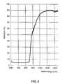
- the blackened anodizing absorbs light At a wavelength of 780 nm has the blackened anodized coating has a reflectivity of 55%, which increases with increasing Wavelength at about 1200 nm continuously to a value of 90% of that on the anodized layer Incident radiation increases.
- the reflector according to the invention offers therefore a cost effective alternative to traditional gold coated infrared reflectors.
- the reflector according to the invention with a commercial Halogen bulb can be combined to a high efficiency infrared radiator, because the halogen bulb takes most of its energy in the form of infrared radiation in the wavelength range above 780 nm and that of the halogen incandescent lamp emitted light from the blackened Eloxal harsh largely is absorbed.
- the reflectance of the reflector according to the invention advantageously by means of a translucent, Infrared rays reflecting interference filter, which is on the blackened Eloxal harsh is arranged.
- the reflector is for cost reasons preferably made of aluminum.
- the infrared radiator according to the invention has a halogen incandescent lamp as a radiation source and a reflector having at least one blackened anodized layer is provided.
- a halogen incandescent lamp as a radiation source
- a reflector having at least one blackened anodized layer is provided.
- the blackened anodizing layer receives the surface of the Reflectors a high reflectivity for infrared radiation in the wavelength range above 780nm and at the same time there is a maximum suppression for radiation ensured from the visible spectral range, as the blackened anodizing absorbs light.
- the halogen bulb takes most of its energy in Form emits infrared radiation in the wavelength range above 780 nm and the light emitted from the halogen incandescent lamp from the blackened anodizing layer is largely absorbed, almost no radiation from the visible Spectral range reflected at the reflector.
- the infrared radiator according to the invention operates particularly efficient for infrared radiation from the wavelength range of 1200 nm to 2500 nm, since the reflectance of the blackened anodized layer in this Wavelength range is about 90%.
- the reflector can additionally with a translucent, infrared radiation be coated reflective interference filter, which on the blackened anodizing is arranged.
- the lamp bulb of the halogen light bulb with one advantage Cold mirror provided the light generated by the filament into the lamp vessel reflected back and is transparent to infrared radiation.
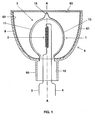
- the infrared radiator shown in FIG. 1 has a halogen incandescent lamp as the radiation source 1 with an electrical power consumption of about 50 watts.
- she has a single-sided sealed quartz glass lamp vessel.
- a filament 2 made of tungsten arranged by means of two from the sealed end 10 of the lamp vessel outstanding power supplies 3, 4 is supplied with electrical energy.
- the surrounding the filament Area 11 of the lamp vessel is provided with an interference filter designed as a cold light mirror 13, which is transparent to infrared radiation and that of the Incandescent generated light for Wendeletzloomung reflected back into the lamp vessel.
- the interference filter 13 also extends over the top 12 of the lamp vessel.
- the infrared radiator also has a cup-shaped, preferably parabolic Reflector 6, whose base body 8 is made of aluminum and its halogen bulb 1 facing inside with a blackened anodized 61st is provided.
- This blackened anodized layer is an anodized layer with the color EV6 according to the name of the anodizing band.
- the reflector 6 encloses the halogen incandescent lamp 1.
- the sealed end 10 of the lamp vessel the halogen incandescent lamp 1 is arranged in the reflector neck 80.
- an interference filter 62 can be applied, the infrared rays reflected and transmitted light.
- the reflector opening by means of an opaque, Be covered by infrared radiation transmitting cover 63, to suppress the emission of light.
Landscapes
- Engineering & Computer Science (AREA)
- General Engineering & Computer Science (AREA)
- Optical Filters (AREA)
- Resistance Heating (AREA)
- Non-Portable Lighting Devices Or Systems Thereof (AREA)
- Optical Elements Other Than Lenses (AREA)
- Control Of Resistance Heating (AREA)
Applications Claiming Priority (2)
| Application Number | Priority Date | Filing Date | Title |
|---|---|---|---|
| DE10341502A DE10341502A1 (de) | 2003-09-05 | 2003-09-05 | Infrarotreflektor und Infrarotstrahler mit einem Infrarotreflektor |
| DE10341502 | 2003-09-05 |
Publications (1)
| Publication Number | Publication Date |
|---|---|
| EP1512903A1 true EP1512903A1 (fr) | 2005-03-09 |
Family
ID=34129709
Family Applications (1)
| Application Number | Title | Priority Date | Filing Date |
|---|---|---|---|
| EP04019864A Withdrawn EP1512903A1 (fr) | 2003-09-05 | 2004-08-20 | Réflecteur à l'infrarouge et lampe à l'infrarouge à réflecteur à l'infrarouge |
Country Status (6)
| Country | Link |
|---|---|
| US (1) | US7061168B2 (fr) |
| EP (1) | EP1512903A1 (fr) |
| JP (1) | JP2005084677A (fr) |
| CN (1) | CN100381837C (fr) |
| CA (1) | CA2479871A1 (fr) |
| DE (1) | DE10341502A1 (fr) |
Cited By (1)
| Publication number | Priority date | Publication date | Assignee | Title |
|---|---|---|---|---|
| WO2008025574A1 (fr) * | 2006-08-28 | 2008-03-06 | Patent-Treuhand-Gesellschaft für elektrische Glühlampen mbH | Module d'éclairage avec au moins une source de lumière et un réflecteur |
Families Citing this family (9)
| Publication number | Priority date | Publication date | Assignee | Title |
|---|---|---|---|---|
| US20070138926A1 (en) * | 2005-12-16 | 2007-06-21 | Brown Peter W | Method for optimizing lamp spectral output |
| EP2308267A2 (fr) * | 2008-07-25 | 2011-04-13 | Speziallampenfabrik Dr. Fischer GmbH | Filtre infrarouge dans une source lumineuse destinée à chauffer un objet |
| US9091151B2 (en) | 2009-11-19 | 2015-07-28 | Halliburton Energy Services, Inc. | Downhole optical radiometry tool |
| AU2009356978B2 (en) | 2009-12-23 | 2013-08-01 | Halliburton Energy Services, Inc. | Interferometry-based downhole analysis tool |
| BR112012027653A2 (pt) | 2010-06-01 | 2016-08-16 | Halliburton Energy Services Inc | método e sistema para medir propriedades de formação |
| AU2010355321B2 (en) * | 2010-06-16 | 2014-02-27 | Halliburtion Energy Services, Inc. | Downhole sources having enhanced IR emission |
| DE102011006670A1 (de) | 2011-04-01 | 2012-10-04 | Aloys Wobben | Windenergieanlage und Verfahren zum Betreiben einer Windenergieanlage |
| CN109519731B (zh) * | 2018-12-07 | 2025-02-11 | 漳州立达信光电子科技有限公司 | 双层球泡灯 |
| WO2021099205A1 (fr) * | 2019-11-21 | 2021-05-27 | Signify Holding B.V. | Mise en forme de faisceau pour des systèmes de filaments de del en spirale |
Citations (4)
| Publication number | Priority date | Publication date | Assignee | Title |
|---|---|---|---|---|
| DE2526773A1 (de) * | 1975-06-14 | 1976-12-30 | Zeiss Ikon Ag | Mit entladungslampe(n) betriebene leuchte |
| DE19540018C1 (de) * | 1995-10-27 | 1997-03-13 | Manfred Becker | Verfahren zur Herstellung eines Reflektors für Niedervoltlampen |
| EP0895032A1 (fr) | 1997-08-02 | 1999-02-03 | Philips Patentverwaltung GmbH | Appareil de chauffage à rayonnement |
| EP1072841A2 (fr) | 1999-07-28 | 2001-01-31 | Oxley Developments Company Limited | Lampe infrarouge |
Family Cites Families (11)
| Publication number | Priority date | Publication date | Assignee | Title |
|---|---|---|---|---|
| US2181292A (en) * | 1937-11-02 | 1939-11-28 | Hygrade Sylvania Corp | Reflector bulb lamp |
| US3188513A (en) * | 1963-04-10 | 1965-06-08 | Gen Electric | Optical filters and lamps embodying the same |
| DE3763511D1 (de) * | 1986-04-16 | 1990-08-09 | Philips Nv | Elektrische lampe mit verspiegeltem kolben. |
| JPH0756792B2 (ja) * | 1987-03-27 | 1995-06-14 | ウシオ電機株式会社 | ヒ−タランプ |
| EP0577196A1 (fr) * | 1992-07-01 | 1994-01-05 | Koninklijke Philips Electronics N.V. | Luminaire infrarouge de chauffage de locaux |
| US5977694A (en) * | 1994-03-22 | 1999-11-02 | Tailored Lighting Inc. | Apertured daylight lamp |
| CN1114329A (zh) * | 1994-06-29 | 1996-01-03 | 清远八达新技术开发公司 | 一种常温远红外辐射涂料 |
| JP2873427B2 (ja) * | 1994-08-03 | 1999-03-24 | 積水化学工業株式会社 | 暖房装置 |
| JPH08292308A (ja) * | 1995-04-24 | 1996-11-05 | Toshiba Lighting & Technol Corp | 反射体およびこれを用いた反射形照明装置 |
| US6393211B1 (en) * | 1997-04-28 | 2002-05-21 | Les Importations Dmd Inc. | Heat radiator assembly |
| JP2003279824A (ja) * | 2002-03-22 | 2003-10-02 | Fuji Photo Optical Co Ltd | 光学装置用機構部品 |
-
2003
- 2003-09-05 DE DE10341502A patent/DE10341502A1/de not_active Withdrawn
-
2004
- 2004-08-20 EP EP04019864A patent/EP1512903A1/fr not_active Withdrawn
- 2004-08-26 JP JP2004247419A patent/JP2005084677A/ja active Pending
- 2004-08-30 US US10/928,113 patent/US7061168B2/en not_active Expired - Lifetime
- 2004-09-01 CA CA002479871A patent/CA2479871A1/fr not_active Abandoned
- 2004-09-04 CN CNB2004100794801A patent/CN100381837C/zh not_active Expired - Fee Related
Patent Citations (4)
| Publication number | Priority date | Publication date | Assignee | Title |
|---|---|---|---|---|
| DE2526773A1 (de) * | 1975-06-14 | 1976-12-30 | Zeiss Ikon Ag | Mit entladungslampe(n) betriebene leuchte |
| DE19540018C1 (de) * | 1995-10-27 | 1997-03-13 | Manfred Becker | Verfahren zur Herstellung eines Reflektors für Niedervoltlampen |
| EP0895032A1 (fr) | 1997-08-02 | 1999-02-03 | Philips Patentverwaltung GmbH | Appareil de chauffage à rayonnement |
| EP1072841A2 (fr) | 1999-07-28 | 2001-01-31 | Oxley Developments Company Limited | Lampe infrarouge |
Cited By (1)
| Publication number | Priority date | Publication date | Assignee | Title |
|---|---|---|---|---|
| WO2008025574A1 (fr) * | 2006-08-28 | 2008-03-06 | Patent-Treuhand-Gesellschaft für elektrische Glühlampen mbH | Module d'éclairage avec au moins une source de lumière et un réflecteur |
Also Published As
| Publication number | Publication date |
|---|---|
| JP2005084677A (ja) | 2005-03-31 |
| DE10341502A1 (de) | 2005-03-31 |
| US20050052105A1 (en) | 2005-03-10 |
| CN100381837C (zh) | 2008-04-16 |
| CN1591048A (zh) | 2005-03-09 |
| CA2479871A1 (fr) | 2005-03-05 |
| US7061168B2 (en) | 2006-06-13 |
Similar Documents
| Publication | Publication Date | Title |
|---|---|---|
| DE3685847T2 (de) | Infrarot projektoranordnung. | |
| DE68909668T2 (de) | Fresnel-Reflektor mit mehrflächigen Elementen. | |
| EP1512903A1 (fr) | Réflecteur à l'infrarouge et lampe à l'infrarouge à réflecteur à l'infrarouge | |
| US6808299B2 (en) | Luminaire | |
| US3527974A (en) | Reflector for producing a color corrected light column | |
| DE2644977A1 (de) | Elektrische reflektorlampe | |
| DE19844164B4 (de) | Energiesparlampen mit im Infraroten reflektierendem Film | |
| DE69305927T2 (de) | Scheinwerfer für Kraftfahrzeuge | |
| DE10319008A1 (de) | Infrarotstrahler und Bestrahlungsvorrichtung | |
| EP1513189A1 (fr) | Réflecteur infrarouge, et radiateur infrarouge avec un tel réflecteur | |
| EP0577196A1 (fr) | Luminaire infrarouge de chauffage de locaux | |
| DE3704501C2 (de) | Leuchte | |
| DE69205862T2 (de) | Bogenentladungslampe mit beschränkter U.V.-Ausstrahlung für Fahrzeuge. | |
| DE3527878A1 (de) | Fahrzeuglampe, insbesondere scheinwerfer | |
| DE3115024C2 (fr) | ||
| US20050052869A1 (en) | Anti-collision light for aircraft | |
| EP0067892A1 (fr) | Dispositif pour l'émission de lumière et d'autres radiations | |
| DE4323422C2 (de) | Reflektoranordnung mit einem rinnenförmigen Reflektor | |
| DE3427461A1 (de) | Lichtabgabevorrichtung, insbesondere fuer kraftfahrzeuge | |
| EP0336244B1 (fr) | Luminaire à boîtier transparent | |
| CH676385A5 (fr) | ||
| JPS6414801A (en) | Head lamp for vehicle | |
| DE10359181B4 (de) | Leuchte für Fahrzeuge | |
| DE19621853A1 (de) | Verfahren zur Bestrahlung eines Beleuchtungsfeldes und Beleuchtungsanordnung | |
| DE1801627C (de) | Stufenreflektor fur Scheinwerferleuch te |
Legal Events
| Date | Code | Title | Description |
|---|---|---|---|
| PUAI | Public reference made under article 153(3) epc to a published international application that has entered the european phase |
Free format text: ORIGINAL CODE: 0009012 |
|
| AK | Designated contracting states |
Kind code of ref document: A1 Designated state(s): AT BE BG CH CY CZ DE DK EE ES FI FR GB GR HU IE IT LI LU MC NL PL PT RO SE SI SK TR |
|
| AX | Request for extension of the european patent |
Extension state: AL HR LT LV MK |
|
| 17P | Request for examination filed |
Effective date: 20050404 |
|
| AKX | Designation fees paid |
Designated state(s): AT BE BG CH CY CZ DE DK EE ES FI FR GB GR HU IE IT LI LU MC NL PL PT RO SE SI SK TR |
|
| STAA | Information on the status of an ep patent application or granted ep patent |
Free format text: STATUS: THE APPLICATION IS DEEMED TO BE WITHDRAWN |
|
| 18D | Application deemed to be withdrawn |
Effective date: 20101026 |